
FSM7226RS / FSM7250RS Hardware Installation Guide
Page 2
...://www.netgear.com Trademarks NETGEAR, the NETGEAR logo, ProSafe, and Auto Uplink are registered trademarks or trademarks of some equipment (for Interference (VCCI) Statement This is used in a domestic environment, radio interference occur, in accordance with the regulations , however, be required to the notes in the operating instructions. NETGEAR does not assume any liability that the NETGEAR ProSafe™ 48-Port L2+ Managed Stackable Switch with 2 Gigabit ports FSM7250RS...
...://www.netgear.com Trademarks NETGEAR, the NETGEAR logo, ProSafe, and Auto Uplink are registered trademarks or trademarks of some equipment (for Interference (VCCI) Statement This is used in a domestic environment, radio interference occur, in accordance with the regulations , however, be required to the notes in the operating instructions. NETGEAR does not assume any liability that the NETGEAR ProSafe™ 48-Port L2+ Managed Stackable Switch with 2 Gigabit ports FSM7250RS...
FSM7226RS / FSM7250RS Hardware Installation Guide
Page 5
... and LEDs 1-1 FSM7226RS Rear Panel 1-2 FSM7250RS Front Panel and LEDs 1-2 FSM7250RS Rear Panel 1-3 Interpreting the LEDs ...1-3 Safety Instructions ...1-4 Chapter 2 Hardware Installation Package Contents ...2-1 Protecting Against Electrostatic Discharge 2-2 Unpacking the Hardware 2-2 Installation ...2-3 Selecting a Location 2-3 Installing the Switch 2-4 Checking the Installation 2-5 Connecting to Power and Checking the LEDs 2-5 SFP Modules ...2-6 Connecting a Redundant Power Supply 2-6 Stacking ...2-7 Connecting Equipment to the Switch 2-8 RJ-45 Ports ...2-8 Connecting a Console to...
... and LEDs 1-1 FSM7226RS Rear Panel 1-2 FSM7250RS Front Panel and LEDs 1-2 FSM7250RS Rear Panel 1-3 Interpreting the LEDs ...1-3 Safety Instructions ...1-4 Chapter 2 Hardware Installation Package Contents ...2-1 Protecting Against Electrostatic Discharge 2-2 Unpacking the Hardware 2-2 Installation ...2-3 Selecting a Location 2-3 Installing the Switch 2-4 Checking the Installation 2-5 Connecting to Power and Checking the LEDs 2-5 SFP Modules ...2-6 Connecting a Redundant Power Supply 2-6 Stacking ...2-7 Connecting Equipment to the Switch 2-8 RJ-45 Ports ...2-8 Connecting a Console to...
FSM7226RS / FSM7250RS Hardware Installation Guide
Page 7
....0, October 2008 About This Manual The NETGEAR® Managed Layer 2+ Stackable Switches FSM7226RS and FSM7250RS Hardware Installation Guide describes how to highlight information of this manual is intended for readers with intermediate computer and Internet skills. This manual uses the following formats to highlight special messages: Note: This format is used to install, configure and troubleshoot the managed switches. website at http://kbserver.netgear.com. Note: Product updates are described in the...
....0, October 2008 About This Manual The NETGEAR® Managed Layer 2+ Stackable Switches FSM7226RS and FSM7250RS Hardware Installation Guide describes how to highlight information of this manual is intended for readers with intermediate computer and Internet skills. This manual uses the following formats to highlight special messages: Note: This format is used to install, configure and troubleshoot the managed switches. website at http://kbserver.netgear.com. Note: Product updates are described in the...
FSM7226RS / FSM7250RS Hardware Installation Guide
Page 8
... model. • Links to view and print PDF files. Printing a PDF chapter. Select File > Print from the browser menu to your browser window. This manual is dedicated to access the full NETGEAR, Inc. online knowledge base for the Managed Layer 2+ Stackable Fast Ethernet Switch according to these specifications: Product Version Manual Publication Date ProSafe FSM7200RS October 2008 How to Use This Manual The HTML version of the following : • Buttons, and at http://www.adobe.com. - Use...
... model. • Links to view and print PDF files. Printing a PDF chapter. Select File > Print from the browser menu to your browser window. This manual is dedicated to access the full NETGEAR, Inc. online knowledge base for the Managed Layer 2+ Stackable Fast Ethernet Switch according to these specifications: Product Version Manual Publication Date ProSafe FSM7200RS October 2008 How to Use This Manual The HTML version of the following : • Buttons, and at http://www.adobe.com. - Use...
FSM7226RS / FSM7250RS Hardware Installation Guide
Page 11
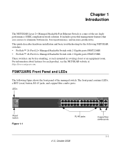
...://www.netgear.com. The front panel contains LEDs, a RST (reset) button, RJ-45 jacks, and copper/fiber combo ports. For information about features for the following figure shows the front panel of -the-art, highperformance, IEEE-compliant network solution. FSM7226RS Front Panel and LEDs The following NETGEAR switches: • ProSafe™ 24-Port L2+ Managed Stackable Switch with 2 Gigabit ports FSM7226RS • ProSafe™ 48-Port L2+ Managed Stackable Switch with 2 Gigabit ports FSM7250RS These switches can use...
...://www.netgear.com. The front panel contains LEDs, a RST (reset) button, RJ-45 jacks, and copper/fiber combo ports. For information about features for the following figure shows the front panel of -the-art, highperformance, IEEE-compliant network solution. FSM7226RS Front Panel and LEDs The following NETGEAR switches: • ProSafe™ 24-Port L2+ Managed Stackable Switch with 2 Gigabit ports FSM7226RS • ProSafe™ 48-Port L2+ Managed Stackable Switch with 2 Gigabit ports FSM7250RS These switches can use...

FSM7226RS / FSM7250RS Hardware Installation Guide
Page 12
Stacking ports Power receptacle Console port Figure 1-2 Redundant power supply connector FSM7250RS Front Panel and LEDs The following figure shows the front panel of the managed switch. The front panel contains LEDs, a RST (reset) button, RJ-45 jacks, and copper/fiber combo ports. Managed Layer 2+ Stackable Switches FSM7226RS and FSM7250RS Hardware Installation Guide FSM7226RS Rear Panel The rear panel has two stacking ports, a console port, redundant power supply connector, and a standard AC power receptacle for the supplied power cord. RST LEDs (reset button) Figure 1-3 RJ-45 ...
Stacking ports Power receptacle Console port Figure 1-2 Redundant power supply connector FSM7250RS Front Panel and LEDs The following figure shows the front panel of the managed switch. The front panel contains LEDs, a RST (reset) button, RJ-45 jacks, and copper/fiber combo ports. Managed Layer 2+ Stackable Switches FSM7226RS and FSM7250RS Hardware Installation Guide FSM7226RS Rear Panel The rear panel has two stacking ports, a console port, redundant power supply connector, and a standard AC power receptacle for the supplied power cord. RST LEDs (reset button) Figure 1-3 RJ-45 ...

FSM7226RS / FSM7250RS Hardware Installation Guide
Page 13
... working. • Blinking green. Stacking ports Power receptacle Console port Figure 1-4 Interpreting the LEDs Power supply connector The following table describes the LEDs on self-test (POST) in progress. • Solid yellow: System is booting up. • Blinking yellow: POST, CPU, or power supply has failed. • Off: Power is disconnected. • Yellow: Fan has failed. • Green: Fan operating normally. • Solid green: The redundant power supply is connected (and using internal power). • Solid yellow: The switch internal power...
... working. • Blinking green. Stacking ports Power receptacle Console port Figure 1-4 Interpreting the LEDs Power supply connector The following table describes the LEDs on self-test (POST) in progress. • Solid yellow: System is booting up. • Blinking yellow: POST, CPU, or power supply has failed. • Off: Power is disconnected. • Yellow: Fan has failed. • Green: Fan operating normally. • Solid green: The redundant power supply is connected (and using internal power). • Solid yellow: The switch internal power...
FSM7226RS / FSM7250RS Hardware Installation Guide
Page 14
... packets. • Yellow: A valid 10/100M link is established on the port. • Off: Stack port does not have a valid link connection. • Green: Stack port has a valid link connection. • Blinking: The stack port is established on the port. Opening or removing covers that are marked with the triangular symbol with a lightning bolt could expose you to electrical shock. Managed Layer 2+ Stackable Switches FSM7226RS and FSM7250RS Hardware Installation Guide Table 1-1. SPD/Link/Act LED • Off:No link...
... packets. • Yellow: A valid 10/100M link is established on the port. • Off: Stack port does not have a valid link connection. • Green: Stack port has a valid link connection. • Blinking: The stack port is established on the port. Opening or removing covers that are marked with the triangular symbol with a lightning bolt could expose you to electrical shock. Managed Layer 2+ Stackable Switches FSM7226RS and FSM7250RS Hardware Installation Guide Table 1-1. SPD/Link/Act LED • Off:No link...
FSM7226RS / FSM7250RS Hardware Installation Guide
Page 17
...the Command Line Interface Reference for the ProSafe 7200RS Series Layer-2 Stackable Switches, the NETGEAR 7000 Series Managed Switch Administration Guide, the NETGEAR Installation Guide for the Managed Stackable Layer 2+ Fast Ethernet Switch models FSM7226RS and FSM7250RS. Chapter 2 Hardware Installation This chapter explains how to install the hardware for the 7000 Series Stackable Managed Switch, and this Hardware Installation Guide • Warranty and Support Card • ProSafe NMS100 Network Management System 30-day trial CD-ROM 2-1 v1.0, October 2008 Configuration software - The...
...the Command Line Interface Reference for the ProSafe 7200RS Series Layer-2 Stackable Switches, the NETGEAR 7000 Series Managed Switch Administration Guide, the NETGEAR Installation Guide for the Managed Stackable Layer 2+ Fast Ethernet Switch models FSM7226RS and FSM7250RS. Chapter 2 Hardware Installation This chapter explains how to install the hardware for the 7000 Series Stackable Managed Switch, and this Hardware Installation Guide • Warranty and Support Card • ProSafe NMS100 Network Management System 30-day trial CD-ROM 2-1 v1.0, October 2008 Configuration software - The...
FSM7226RS / FSM7250RS Hardware Installation Guide
Page 19
...-45 ports, view the front panel LEDs, and access the rear-panel power connector. Managed Layer 2+ Stackable Switches FSM7226RS and FSM7250RS Hardware Installation Guide Installation Install the equipment in the following site requirements. Put the switch in a dry area with your switch. See "Connecting to 55ºC (32º and 131ºF). Provide a flat table or shelf surface. • Rack-mount Installations. Check the installation. Keep at least 2 inches (5.08 centimeters) free on a tabletop). Install the switch...
...-45 ports, view the front panel LEDs, and access the rear-panel power connector. Managed Layer 2+ Stackable Switches FSM7226RS and FSM7250RS Hardware Installation Guide Installation Install the equipment in the following site requirements. Put the switch in a dry area with your switch. See "Connecting to 55ºC (32º and 131ºF). Provide a flat table or shelf surface. • Rack-mount Installations. Check the installation. Keep at least 2 inches (5.08 centimeters) free on a tabletop). Install the switch...
FSM7226RS / FSM7250RS Hardware Installation Guide
Page 21
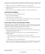
... is not controlled by a wall switch (which can turn off power to the rack. 5. Managed Layer 2+ Stackable Switches FSM7226RS and FSM7250RS Hardware Installation Guide 3. Tighten the screws with troubleshooting, see Chapter 3, "Troubleshooting. Check cable routing to secure the switch in the rack. Tighten the screws with nylon washers to the rear of the switch. If the Power LED does not light up in correctly and that cables are installed correctly. 3. Hardware Installation 2-5 v1.0, October 2008 Checking the Installation Before you...
... is not controlled by a wall switch (which can turn off power to the rack. 5. Managed Layer 2+ Stackable Switches FSM7226RS and FSM7250RS Hardware Installation Guide 3. Tighten the screws with troubleshooting, see Chapter 3, "Troubleshooting. Check cable routing to secure the switch in the rack. Tighten the screws with nylon washers to the rear of the switch. If the Power LED does not light up in correctly and that cables are installed correctly. 3. Hardware Installation 2-5 v1.0, October 2008 Checking the Installation Before you...
FSM7226RS / FSM7250RS Hardware Installation Guide
Page 23
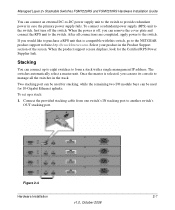
... the product support screen displays, look for 10-Gigabit Ethernet uplinks. Two stacking port can be used for the Certified RPS Power Supplier link. When the power is off the switch. Once the master is compatible with a single management IP address. To set up to eight switches to form a stack with this switch, go to provide redundant power in case the primary power supply fails. Managed Layer 2+ Stackable Switches FSM7226RS and FSM7250RS Hardware Installation Guide You can connect up a stack: 1. Select...
... the product support screen displays, look for 10-Gigabit Ethernet uplinks. Two stacking port can be used for the Certified RPS Power Supplier link. When the power is off the switch. Once the master is compatible with a single management IP address. To set up to eight switches to form a stack with this switch, go to provide redundant power in case the primary power supply fails. Managed Layer 2+ Stackable Switches FSM7226RS and FSM7250RS Hardware Installation Guide You can connect up a stack: 1. Select...
FSM7226RS / FSM7250RS Hardware Installation Guide
Page 24
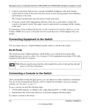
... identify the IP address. Connecting a Console to the Switch After you install the switch and apply power, you can connect to the master switch. You can connect devices, a Gigabit Ethernet module, and/or a console to the switch. To use the Command Line Interface (CLI) to the stack. Managed Layer 2+ Stackable Switches FSM7226RS and FSM7250RS Hardware Installation Guide 3. Finally, connect the last switch in a cascade to attach devices using either straight-through or crossover cables. Note: Ethernet specifications limit the cable length between the switch and the attached...
... identify the IP address. Connecting a Console to the Switch After you install the switch and apply power, you can connect to the master switch. You can connect devices, a Gigabit Ethernet module, and/or a console to the switch. To use the Command Line Interface (CLI) to the stack. Managed Layer 2+ Stackable Switches FSM7226RS and FSM7250RS Hardware Installation Guide 3. Finally, connect the last switch in a cascade to attach devices using either straight-through or crossover cables. Note: Ethernet specifications limit the cable length between the switch and the attached...
FSM7226RS / FSM7250RS Hardware Installation Guide
Page 25
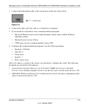
... 2008 Managed Layer 2+ Stackable Switches FSM7226RS and FSM7250RS Hardware Installation Guide 1. Connect the other end of the switch. Configure the terminal-emulation program to configure the switch. Connect the null-modem cable to a workstation or terminal. 3. Console port Figure 2-5 2. The following settings: • Baud rate: 9,600 bps • Data bits: 8 • Parity: none • Stop bit: 1 • Flow control: none After you connect a console to the switch, you attached a workstation, start a terminal-emulation program. • Microsoft Windows users can use...
... 2008 Managed Layer 2+ Stackable Switches FSM7226RS and FSM7250RS Hardware Installation Guide 1. Connect the other end of the switch. Configure the terminal-emulation program to configure the switch. Connect the null-modem cable to a workstation or terminal. 3. Console port Figure 2-5 2. The following settings: • Baud rate: 9,600 bps • Data bits: 8 • Parity: none • Stop bit: 1 • Flow control: none After you connect a console to the switch, you attached a workstation, start a terminal-emulation program. • Microsoft Windows users can use...
FSM7226RS / FSM7250RS Hardware Installation Guide
Page 27
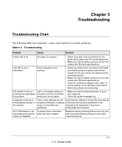
... 2008 ACT LED flashes on • Make sure that there is properly inserted and locked into the port at the switch and the connected device. • Make sure that the cabling is not recognized as part of possible problems. Table 3-1. or full-duplex setting on all A network loop (redundant connected ports and the path) has been created. device are correct and comply with Ethernet specifications. One or...
... 2008 ACT LED flashes on • Make sure that there is properly inserted and locked into the port at the switch and the connected device. • Make sure that the cabling is not recognized as part of possible problems. Table 3-1. or full-duplex setting on all A network loop (redundant connected ports and the path) has been created. device are correct and comply with Ethernet specifications. One or...
FSM7226RS / FSM7250RS Hardware Installation Guide
Page 28
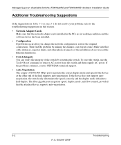
... the software driver has been installed. • Configuration If problems occur after you change the network configuration, restore the original connections. Make sure that the attached device supports auto-negotiation. 3-2 Troubleshooting v1.0, October 2008 Managed Layer 2+ Stackable Switches FSM7226RS and FSM7250RS Hardware Installation Guide Additional Troubleshooting Suggestions If the suggestions in Table 3-1 on page 3-1 do not exceed the Ethernet limitations. • Switch Integrity You can verify the integrity of the link supports auto-negotiation. To reset the switch, use...
... the software driver has been installed. • Configuration If problems occur after you change the network configuration, restore the original connections. Make sure that the attached device supports auto-negotiation. 3-2 Troubleshooting v1.0, October 2008 Managed Layer 2+ Stackable Switches FSM7226RS and FSM7250RS Hardware Installation Guide Additional Troubleshooting Suggestions If the suggestions in Table 3-1 on page 3-1 do not exceed the Ethernet limitations. • Switch Integrity You can verify the integrity of the link supports auto-negotiation. To reset the switch, use...
FSM7226RS / FSM7250RS Hardware Installation Guide
Page 29
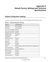
... Flow control (half duplex) Enabled Flow control (full duplex) Disabled Broadcast storm control Enabled Gigabit port type Auto detect Management IP configuration DHCP Password protection Disabled User name Admin Password (none) Web access Enabled Java mode Enabled VLAN All ports belong to default VLAN (VLAN 1) as untagged ports IP multicast filtering Disabled Spanning Tree Protocol Enabled (IEEE 802.1s) Admin edge port Enabled Link aggregation Disabled Port mirroring Disabled Traffic prioritization Disabled Default Factory Settings and Technical Specifications...
... Flow control (half duplex) Enabled Flow control (full duplex) Disabled Broadcast storm control Enabled Gigabit port type Auto detect Management IP configuration DHCP Password protection Disabled User name Admin Password (none) Web access Enabled Java mode Enabled VLAN All ports belong to default VLAN (VLAN 1) as untagged ports IP multicast filtering Disabled Spanning Tree Protocol Enabled (IEEE 802.1s) Admin edge port Enabled Link aggregation Disabled Port mirroring Disabled Traffic prioritization Disabled Default Factory Settings and Technical Specifications...
FSM7226RS / FSM7250RS Hardware Installation Guide
Page 30
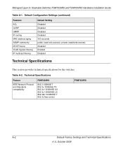
... IP routing MAC address aging SNMP community DHCP Server VLAN Ingress filtering IP multicast filtering Default Setting Disabled Disabled Disabled Disabled 300 seconds public (read-only access), private (read/write access) Disabled Enabled Disabled Technical Specifications This section provides technical specifications for the switches. Technical Specifications Feature IEEE Network Protocol and Standards compatibility FSM7226RS 802.3 10BASE-T 802.3u 100BASE-TX 802.3z 1000BASE-SX 802.3z 1000BASE-LX 802.3ab 1000BASE-T 802.3x flow control FSM7250RS A-2 Default Factory Settings and...
... IP routing MAC address aging SNMP community DHCP Server VLAN Ingress filtering IP multicast filtering Default Setting Disabled Disabled Disabled Disabled 300 seconds public (read-only access), private (read/write access) Disabled Enabled Disabled Technical Specifications This section provides technical specifications for the switches. Technical Specifications Feature IEEE Network Protocol and Standards compatibility FSM7226RS 802.3 10BASE-T 802.3u 100BASE-TX 802.3z 1000BASE-SX 802.3z 1000BASE-LX 802.3ab 1000BASE-T 802.3x flow control FSM7250RS A-2 Default Factory Settings and...
FSM7226RS / FSM7250RS Hardware Installation Guide
Page 31
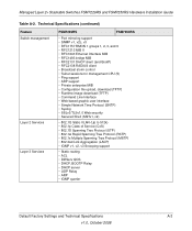
... Guide Table A-2. Technical Specifications (continued) Feature Switch management Layer 2 Services Layer 3 Services FSM7226RS FSM7250RS • Port mirroring support • SNMP v1, v2c, v3 • RFC1757 RMON 1 groups 1, 2, 3, and 9 • RFC1213 MIB II • RFC1643 Ethernet Interface MIB • RFC1493 bridge MIB • RFC2131 DHCP client (and BootP) • RFC2138 RADIUS client • Broadcast storm control • Telnet sessions for management CPU (5) • Ping support • ARP support • Private enterprise MIB • Configuration file upload, download (TFTP...
... Guide Table A-2. Technical Specifications (continued) Feature Switch management Layer 2 Services Layer 3 Services FSM7226RS FSM7250RS • Port mirroring support • SNMP v1, v2c, v3 • RFC1757 RMON 1 groups 1, 2, 3, and 9 • RFC1213 MIB II • RFC1643 Ethernet Interface MIB • RFC1493 bridge MIB • RFC2131 DHCP client (and BootP) • RFC2138 RADIUS client • Broadcast storm control • Telnet sessions for management CPU (5) • Ping support • ARP support • Private enterprise MIB • Configuration file upload, download (TFTP...
FSM7226RS / FSM7250RS Hardware Installation Guide
Page 32
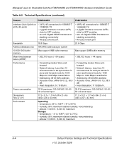
... transmission • Addressing: 48-bit MAC address • Acoustic noise: (ANSI-S10.12): 38.3 dB • Heat dissipation: 111.92Btu/hr. Managed Layer 2+ Stackable Switches FSM7226RS and FSM7250RS Hardware Installation Guide Table A-2. Technical Specifications (continued) Feature FSM7226RS FSM7250RS Interface (Auto Uplink on all RJ-45 ports) • 24 RJ-45 connectors for 10BASE-T, 100BASE-TX • 2 gigabit interface converter (SFP) slots for SFP modules • two 2.5-Gigabit HDMI interfaces for stacking connectivity • RS-232 console port • 48...
... transmission • Addressing: 48-bit MAC address • Acoustic noise: (ANSI-S10.12): 38.3 dB • Heat dissipation: 111.92Btu/hr. Managed Layer 2+ Stackable Switches FSM7226RS and FSM7250RS Hardware Installation Guide Table A-2. Technical Specifications (continued) Feature FSM7226RS FSM7250RS Interface (Auto Uplink on all RJ-45 ports) • 24 RJ-45 connectors for 10BASE-T, 100BASE-TX • 2 gigabit interface converter (SFP) slots for SFP modules • two 2.5-Gigabit HDMI interfaces for stacking connectivity • RS-232 console port • 48...


