EN516 Installation Guide
Page 2
...comply with the instruction manual, it is not installed and used in which case users will be necessary to Part 15 of the FCC rules. Lesen Sie dazu bitte die Anmerkungen in this equipment in a residential area is a registered trademark of shielded data cables. Der Benutzer... the Bay Networks NETGEAR Model EN516 Ethernet Hub is shielded against harmful interference when the equipment is dependent upon the use or application of NETGEAR, Inc. Bestätigung des Herstellers/Importeurs Es wird hiermit bestätigt, daß das NETGEAR Model EN516 Ethernet Hub gemäß...
...comply with the instruction manual, it is not installed and used in which case users will be necessary to Part 15 of the FCC rules. Lesen Sie dazu bitte die Anmerkungen in this equipment in a residential area is a registered trademark of shielded data cables. Der Benutzer... the Bay Networks NETGEAR Model EN516 Ethernet Hub is shielded against harmful interference when the equipment is dependent upon the use or application of NETGEAR, Inc. Bestätigung des Herstellers/Importeurs Es wird hiermit bestätigt, daß das NETGEAR Model EN516 Ethernet Hub gemäß...
EN516 Installation Guide
Page 3
... (URL) http:// www.NETGEAR.com. Voluntary Control Council for example, test transmitters) in an adjacent area thereto, radio interference may , however, be caused to certain restrictions. Certificate of the Manufacturer/Importer It is hereby certified that the NETGEAR Model EN516 Ethernet Hub has been suppressed in accordance with the conditions set by Data Processing Equipment and...
... (URL) http:// www.NETGEAR.com. Voluntary Control Council for example, test transmitters) in an adjacent area thereto, radio interference may , however, be caused to certain restrictions. Certificate of the Manufacturer/Importer It is hereby certified that the NETGEAR Model EN516 Ethernet Hub has been suppressed in accordance with the conditions set by Data Processing Equipment and...
EN516 Installation Guide
Page 11
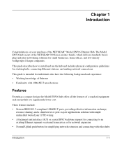
...-density workgroups of Ethernet • Familiarity with other hubs Introduction 1-1 Chapter 1 Introduction Congratulations on your purchase of a standard equipment rack-mount hub at a significantly lower cost. This guide is part of the NETGEAR 500 Series product family, which delivers standards-based, plug-and-play networking solutions for individuals who have the following background and experience: • Working knowledge of...
...-density workgroups of Ethernet • Familiarity with other hubs Introduction 1-1 Chapter 1 Introduction Congratulations on your purchase of a standard equipment rack-mount hub at a significantly lower cost. This guide is part of the NETGEAR 500 Series product family, which delivers standards-based, plug-and-play networking solutions for individuals who have the following background and experience: • Working knowledge of...
EN516 Installation Guide
Page 12
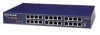
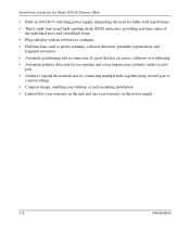
Installation Guide for the Model EN516 Ethernet Hub • Built-in 100-240 V switching power supply, eliminating the need for bulky wall transformers • Thirty-eight front panel light emitting diode (LED) indicators, providing real-time status of the individual ports and overall hub status • Plug-and-play with no software to configure • Hub functions such as packet retiming, collision detection, preamble regeneration, and fragment...
Installation Guide for the Model EN516 Ethernet Hub • Built-in 100-240 V switching power supply, eliminating the need for bulky wall transformers • Thirty-eight front panel light emitting diode (LED) indicators, providing real-time status of the individual ports and overall hub status • Plug-and-play with no software to configure • Hub functions such as packet retiming, collision detection, preamble regeneration, and fragment...
EN516 Installation Guide
Page 14
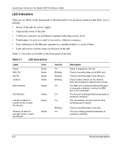
... • Data utilization of the Ethernet segment in a standalone hub or a stack of hubs • Link and receive activity status for all ports in the hub Table 2-1 describes each LED on the front panel of each RJ-45 port) Yellow Green Yellow Activity On Blinking Blinking Blinking On On On Blinking On Description Power is incoming data on the network. Table 2-1. There is supplied to the hub. There is not connected. The AUI port is...
... • Data utilization of the Ethernet segment in a standalone hub or a stack of hubs • Link and receive activity status for all ports in the hub Table 2-1 describes each LED on the front panel of each RJ-45 port) Yellow Green Yellow Activity On Blinking Blinking Blinking On On On Blinking On Description Power is incoming data on the network. Table 2-1. There is supplied to the hub. There is not connected. The AUI port is...
EN516 Installation Guide
Page 15
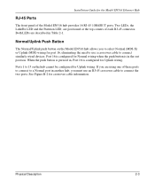
... for Uplink wiring. Installation Guide for the Model EN516 Ethernet Hub RJ-45 Ports The front panel of each RJ-45 connector. Both LEDs are using one of these ports to connect to a Normal port in another hub, you must use a crossover cable to 15 on the Model EN516 hub allows you are described in the out position. When the push button is pressed in, Port 16 is in Table...
... for Uplink wiring. Installation Guide for the Model EN516 Ethernet Hub RJ-45 Ports The front panel of each RJ-45 connector. Both LEDs are using one of these ports to connect to a Normal port in another hub, you must use a crossover cable to 15 on the Model EN516 hub allows you are described in the out position. When the push button is pressed in, Port 16 is in Table...
EN516 Installation Guide
Page 16
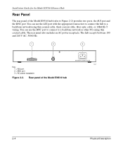
... 240 V AC, 50/60 Hz. 1 2 3 BNC AUI Key: 1 = AUI port 2 = BNC port 3 = AC power receptacle Figure 2-2. You can use the AUI port with the appropriate transceiver to connect the hub to Figure 2-2) provides two ports, the AUI port and the BNC port. Installation Guide for the Model EN516 Ethernet Hub Rear Panel The rear panel of the Model EN516 hub 100-240 VAC 50-60 Hz 0.15A 7147...
... 240 V AC, 50/60 Hz. 1 2 3 BNC AUI Key: 1 = AUI port 2 = BNC port 3 = AC power receptacle Figure 2-2. You can use the AUI port with the appropriate transceiver to connect the hub to Figure 2-2) provides two ports, the AUI port and the BNC port. Installation Guide for the Model EN516 Ethernet Hub Rear Panel The rear panel of the Model EN516 hub 100-240 VAC 50-60 Hz 0.15A 7147...
EN516 Installation Guide
Page 18
Installation Guide for the Model EN516 Ethernet Hub • AC power cord • Rack mount kit • Four rubber pads for installation on a flat surface • One BNC T-connector • One BNC terminator • Warranty and Owner Registration Card Caution: Use the appropriate power cord as required by your dealer if there are any special tools. Unpack the hub. 2. Follow the instructions for repair. Keep...
Installation Guide for the Model EN516 Ethernet Hub • AC power cord • Rack mount kit • Four rubber pads for installation on a flat surface • One BNC T-connector • One BNC terminator • Warranty and Owner Registration Card Caution: Use the appropriate power cord as required by your dealer if there are any special tools. Unpack the hub. 2. Follow the instructions for repair. Keep...
EN516 Installation Guide
Page 19
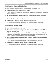
... hub. 2. Attach the mounting brackets (supplied in your stack. Installation 3-3 Restricted air flow could cause overheating. 3. Attach the hub (with the mounting bracket) to secure each marked location on a tabletop or shelf so that it has at each bracket. 2. Use a #2 Phillips screwdriver and tighten the screws to secure the hub to "Connecting the Hub" on all sides. Installation Guide for the Model EN516 Ethernet Hub Installing...
... hub. 2. Attach the mounting brackets (supplied in your stack. Installation 3-3 Restricted air flow could cause overheating. 3. Attach the hub (with the mounting bracket) to secure each marked location on a tabletop or shelf so that it has at each bracket. 2. Use a #2 Phillips screwdriver and tighten the screws to secure the hub to "Connecting the Hub" on all sides. Installation Guide for the Model EN516 Ethernet Hub Installing...
EN516 Installation Guide
Page 20
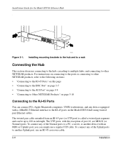
... device with a 10BASE-T Ethernet interface to another Uplink port, use a regular UTP cable. Power Data Collision 1 Link RX 9 Link RX 8 Normal/Uplink 16 Figure 3-1. 7171 Installing mounting brackets to the hub and to a rack Connecting the Hub This section discusses connecting to the hub, cascading to multiple hubs, and connecting to 100 m in length. To connect any device equipped with an MDI (or Uplink) port, you can be up to other NETGEAR products, refer to the following...
... device with a 10BASE-T Ethernet interface to another Uplink port, use a regular UTP cable. Power Data Collision 1 Link RX 9 Link RX 8 Normal/Uplink 16 Figure 3-1. 7171 Installing mounting brackets to the hub and to a rack Connecting the Hub This section discusses connecting to the hub, cascading to multiple hubs, and connecting to 100 m in length. To connect any device equipped with an MDI (or Uplink) port, you can be up to other NETGEAR products, refer to the following...
EN516 Installation Guide
Page 21
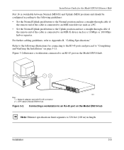
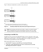
... Key: 1 = Network adapter card with RJ-45 connector 2 = UTP cable to Model EN516 hub Power Data Collision 1 Link RX 9 Link RX 8 Normal/Uplink 16 34FA Figure 3-2. Figure 3-2 illustrates a workstation connected to an RJ-45 port on the Model EN516 hub Note: Ethernet specifications limit segments to 328 feet (100 m) in length. Refer to the following guidelines: • Set the Normal/Uplink push button to the Normal position and use...
... Key: 1 = Network adapter card with RJ-45 connector 2 = UTP cable to Model EN516 hub Power Data Collision 1 Link RX 9 Link RX 8 Normal/Uplink 16 34FA Figure 3-2. Figure 3-2 illustrates a workstation connected to an RJ-45 port on the Model EN516 hub Note: Ethernet specifications limit segments to 328 feet (100 m) in length. Refer to the following guidelines: • Set the Normal/Uplink push button to the Normal position and use...
EN516 Installation Guide
Page 22
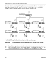
... "B," the communication path goes from hub 5 to cascade hubs together. For example, when PC "A" communicates with the Normal/Uplink push button set to Uplink position Figure 3-3. Figure 3-3 illustrates multiple hubs cascaded in a hierarchical star through hubs 2, 1, and 4. 3-6 Installation The RJ-45, BNC, or AUI ports can be used to hub 7, passing through the RJ-45 ports Note: Ethernet specifications limit the number of users supported on the network.
... "B," the communication path goes from hub 5 to cascade hubs together. For example, when PC "A" communicates with the Normal/Uplink push button set to Uplink position Figure 3-3. Figure 3-3 illustrates multiple hubs cascaded in a hierarchical star through hubs 2, 1, and 4. 3-6 Installation The RJ-45, BNC, or AUI ports can be used to hub 7, passing through the RJ-45 ports Note: Ethernet specifications limit the number of users supported on the network.
EN516 Installation Guide
Page 23
... the Model EN516 hub. 2. Connecting to a thin coaxial segment. Installation 3-7 By using the BNC interface, follow these steps: 1. Installation Guide for the Model EN516 Ethernet Hub Figure 3-4 illustrates multiple hubs cascaded in a daisy-chain style. 1 Model EN516 hub 2 Model EN516 hub 3 Model EN516 hub 000029EA Key: 1 = Model EN516 hub with Normal/Uplink push button set to Normal position 2 and 3 = Model EN516 hub with Normal/Uplink push button set to the BNC port or several Model EN516 hubs as shown in Figure 3-5. You can connect servers...
... the Model EN516 hub. 2. Connecting to a thin coaxial segment. Installation 3-7 By using the BNC interface, follow these steps: 1. Installation Guide for the Model EN516 Ethernet Hub Figure 3-4 illustrates multiple hubs cascaded in a daisy-chain style. 1 Model EN516 hub 2 Model EN516 hub 3 Model EN516 hub 000029EA Key: 1 = Model EN516 hub with Normal/Uplink push button set to Normal position 2 and 3 = Model EN516 hub with Normal/Uplink push button set to the BNC port or several Model EN516 hubs as shown in Figure 3-5. You can connect servers...
EN516 Installation Guide
Page 25
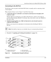
... port. Connect the AUI port on page 3-11. 1 2 3 4 Key: 1 = Cable termination device 2 = 10BASE-5 transceiver 31EA 3 = Thick coaxial cable 4 = Transceiver cable (AUI cable) Figure 3-6. Note: If the SQE test function is not disabled, the port is normally used for connecting a thick coaxial segment. Installation Guide for the Model EN516 Ethernet Hub Connecting to an external coaxial transceiver through the AUI port Installation 3-9 Cascading hubs through an AUI transceiver cable. When using the AUI port, refer to most types...
... port. Connect the AUI port on page 3-11. 1 2 3 4 Key: 1 = Cable termination device 2 = 10BASE-5 transceiver 31EA 3 = Thick coaxial cable 4 = Transceiver cable (AUI cable) Figure 3-6. Note: If the SQE test function is not disabled, the port is normally used for connecting a thick coaxial segment. Installation Guide for the Model EN516 Ethernet Hub Connecting to an external coaxial transceiver through the AUI port Installation 3-9 Cascading hubs through an AUI transceiver cable. When using the AUI port, refer to most types...
EN516 Installation Guide
Page 26
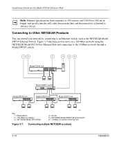
... 56 Model FE516 hub Model SW507 switch Model EN516 hub Model EN516 hub Model EN516 hub Key: 1 = Workstations 2 = 100 Mbps connection 3 = NETGEAR Model FE516 Fast 7228 4 = Server 5 = NETGEAR Model SW507 Ethernet switch 6 = 10 Mbps connection Ethernet hub Figure 3-7. Figure 3-7 illustrates power users on a 100 Mbps network using the NETGEAR Model FE516 Fast Ethernet Hub and connecting to an Ethernet switch, such as the NETGEAR Model SW507 Ethernet Switch. Connecting multiple NETGEAR products 3-10 Installation Installation Guide for the Model EN516 Ethernet Hub Note: Ethernet speci...
... 56 Model FE516 hub Model SW507 switch Model EN516 hub Model EN516 hub Model EN516 hub Key: 1 = Workstations 2 = 100 Mbps connection 3 = NETGEAR Model FE516 Fast 7228 4 = Server 5 = NETGEAR Model SW507 Ethernet switch 6 = 10 Mbps connection Ethernet hub Figure 3-7. Figure 3-7 illustrates power users on a 100 Mbps network using the NETGEAR Model FE516 Fast Ethernet Hub and connecting to an Ethernet switch, such as the NETGEAR Model SW507 Ethernet Switch. Connecting multiple NETGEAR products 3-10 Installation Installation Guide for the Model EN516 Ethernet Hub Note: Ethernet speci...
EN516 Installation Guide
Page 27
... problems, refer to the hub, the following conditions should exist: • Green Power LED on the front panel is on. • Yellow BNC Partition LED is on if the BNC port is not connected. • Green Link/Rx LED on each connected port is on the wall. When power has been applied to Chapter 4, "Troubleshooting." Installation 3-11 Installation Guide for the Model EN516 Ethernet Hub Completing and Verifying the Installation To complete the installation, connect...
... problems, refer to the hub, the following conditions should exist: • Green Power LED on the front panel is on. • Yellow BNC Partition LED is on if the BNC port is not connected. • Green Link/Rx LED on each connected port is on the wall. When power has been applied to Chapter 4, "Troubleshooting." Installation 3-11 Installation Guide for the Model EN516 Ethernet Hub Completing and Verifying the Installation To complete the installation, connect...
EN516 Installation Guide
Page 30
... ports turns on when the port is established successfully between the hub and a PC or other device. AUI Rx LED and BNC Rx LED for the AUI and BNC Ports The green AUI Rx LED and BNC Rx LED blink when there is data reception on pin assignment and cable specifications, refer to see whether or not there is reconnected. Installation Guide for the Model...
... ports turns on when the port is established successfully between the hub and a PC or other device. AUI Rx LED and BNC Rx LED for the AUI and BNC Ports The green AUI Rx LED and BNC Rx LED blink when there is data reception on pin assignment and cable specifications, refer to see whether or not there is reconnected. Installation Guide for the Model...
EN516 Installation Guide
Page 32
... network configuration, restore the original connections and determine the problem by resetting it. If the problem continues and you have completed all the preceding diagnoses, contact Customer Support. See page iii for the Model EN516 Ethernet Hub Network Interface Cards Make sure the network interface cards installed in the workstations are in your area. 4-4 Troubleshooting Turn off the power to the switch and then turn the power to the switch...
... network configuration, restore the original connections and determine the problem by resetting it. If the problem continues and you have completed all the preceding diagnoses, contact Customer Support. See page iii for the Model EN516 Ethernet Hub Network Interface Cards Make sure the network interface cards installed in the workstations are in your area. 4-4 Troubleshooting Turn off the power to the switch and then turn the power to the switch...
EN516 Installation Guide
Page 44
... Ethernet Hub connector AUI pin assignments (table) C-2 BNC C-3 BNC-T C-4 RJ-45 pin assignments (table) C-1 crossover twisted pair cable B-2 customer support iii D daisy-chain cascade 3-7 F FCC statement ii features 1-1 front panel 2-1 H hierarchical star cascade 3-6 I installation cascading ports 3-4 to 3-9 completing 3-11 connecting ports 3-4 to 3-9 connecting to NETGEAR products 3-10 daisy-chain style 3-7 in a rack 3-3 network interface cards 4-4 on a flat surface 3-3 package contents 3-1 tools required 3-2 troubleshooting 4-3 verifying 3-11, 4-4 L LEDs...
... Ethernet Hub connector AUI pin assignments (table) C-2 BNC C-3 BNC-T C-4 RJ-45 pin assignments (table) C-1 crossover twisted pair cable B-2 customer support iii D daisy-chain cascade 3-7 F FCC statement ii features 1-1 front panel 2-1 H hierarchical star cascade 3-6 I installation cascading ports 3-4 to 3-9 completing 3-11 connecting ports 3-4 to 3-9 connecting to NETGEAR products 3-10 daisy-chain style 3-7 in a rack 3-3 network interface cards 4-4 on a flat surface 3-3 package contents 3-1 tools required 3-2 troubleshooting 4-3 verifying 3-11, 4-4 L LEDs...
EN516 Installation Guide
Page 45
... 2-3 using crossover cable 3-4 using transceivers to 3-9 RJ-45 2-3 using straight-through cable 3-5 W warranty 1-2 World Wide Web iii S site preparation 3-1 straight-through twisted pair cable B-2 Index 3 Installation Guide for the Model EN516 Ethernet Hub P package contents 3-1 ports See also AUI See also BNC See also RJ-45 AUI 2-4 BNC 2-4 cascading 3-4 to 3-9 connecting 3-4 to connect AUI 3-9 Power LED 2-2, 3-11, 4-1 T technical specifications A-1 technical support iii troubleshooting cable 4-3 configuration 4-4 installation 4-3, 4-4 LEDs 4-1 network interface cards...
... 2-3 using crossover cable 3-4 using transceivers to 3-9 RJ-45 2-3 using straight-through cable 3-5 W warranty 1-2 World Wide Web iii S site preparation 3-1 straight-through twisted pair cable B-2 Index 3 Installation Guide for the Model EN516 Ethernet Hub P package contents 3-1 ports See also AUI See also BNC See also RJ-45 AUI 2-4 BNC 2-4 cascading 3-4 to 3-9 connecting 3-4 to connect AUI 3-9 Power LED 2-2, 3-11, 4-1 T technical specifications A-1 technical support iii troubleshooting cable 4-3 configuration 4-4 installation 4-3, 4-4 LEDs 4-1 network interface cards...


