Owners Manual
Page 2
... measures: Reorient or relocate the receiving antenna. Connect the equipment into an outlet on , the user is connected. The lightning flash with the limits for help. FCC WARNING: To assure continued compliance, follow the attached installation instructions and use only shielded cables when connecting to other devices. NO USER-SERVICEABLE PARTS INSIDE. IMPORTANT SAFETY INSTRUCTIONS CAUTION RISK OF ELECTRIC SHOCK DO NOT OPEN CAUTION: TO REDUCE THE...
... measures: Reorient or relocate the receiving antenna. Connect the equipment into an outlet on , the user is connected. The lightning flash with the limits for help. FCC WARNING: To assure continued compliance, follow the attached installation instructions and use only shielded cables when connecting to other devices. NO USER-SERVICEABLE PARTS INSIDE. IMPORTANT SAFETY INSTRUCTIONS CAUTION RISK OF ELECTRIC SHOCK DO NOT OPEN CAUTION: TO REDUCE THE...
Owners Manual
Page 3
... long periods of the obsolete outlet. 10)Protect the power cord from the wall outlet and disconnect the antenna or cable system. When installing an outside antenna system should not be placed in a built-in the operating instructions should be adhered to rain or moisture does not operate normally, or has been dropped. 15) Power source This product should not be located in...
... long periods of the obsolete outlet. 10)Protect the power cord from the wall outlet and disconnect the antenna or cable system. When installing an outside antenna system should not be placed in a built-in the operating instructions should be adhered to rain or moisture does not operate normally, or has been dropped. 15) Power source This product should not be located in...
Owners Manual
Page 4
... mast and supporting structure, grounding of the lead-in wire to an antenna discharge product, size of grounding conductors, location of antenna-discharge product, connection to grounding electrodes and requirements for proper grounding and, in particular, specifies that have fallen into the product. a) When the power-supply cord or plug is grounded so as the following the operating instructions. b) If...
... mast and supporting structure, grounding of the lead-in wire to an antenna discharge product, size of grounding conductors, location of antenna-discharge product, connection to grounding electrodes and requirements for proper grounding and, in particular, specifies that have fallen into the product. a) When the power-supply cord or plug is grounded so as the following the operating instructions. b) If...
Owners Manual
Page 5
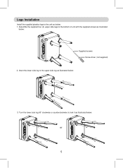
Legs Installation Install the supplied plastics legs to the unit as below : Supplied screws Screw driver (not supplied) 2. Assemble the supplied four (4) upper side legs to the bottom of unit with the supplied screws as illustrated below : 1. Turn the lower side leg 90° clockwise or counterclockwise to the upper side leg as illustrated below : 3. Insert the lower side leg to lock it as illustrated below : or 5
Legs Installation Install the supplied plastics legs to the unit as below : Supplied screws Screw driver (not supplied) 2. Assemble the supplied four (4) upper side legs to the bottom of unit with the supplied screws as illustrated below : 1. Turn the lower side leg 90° clockwise or counterclockwise to the upper side leg as illustrated below : 3. Insert the lower side leg to lock it as illustrated below : or 5
Owners Manual
Page 6
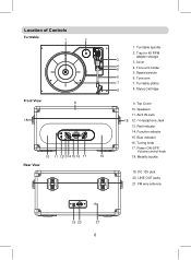
... 45 RPM adapter storage 3 3. Speakers 11. Location of Controls Turntable 1 2 1. Headphone Jack 13. Tuning knob 17. LINE OUT jacks 21. Stylus Cartridge Front View 18 9 94 90 87 FM 98 102 104 106 108 MHz OFF 10 11 121314 15 16 17 10 Rear View 9. Red indicator 14. Speed selector 6 6. Top Cover 10. Blue indicator 16. Turntable spindle 2. Power ON-OFF/ Volume control knob...
... 45 RPM adapter storage 3 3. Speakers 11. Location of Controls Turntable 1 2 1. Headphone Jack 13. Tuning knob 17. LINE OUT jacks 21. Stylus Cartridge Front View 18 9 94 90 87 FM 98 102 104 106 108 MHz OFF 10 11 121314 15 16 17 10 Rear View 9. Red indicator 14. Speed selector 6 6. Top Cover 10. Blue indicator 16. Turntable spindle 2. Power ON-OFF/ Volume control knob...
Owners Manual
Page 7
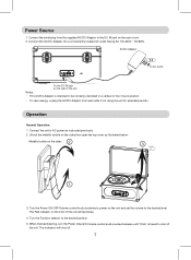
... as instructed previously. 2. The indicators will illuminate. 4. Unlock the metallic buckle on the sides 2 3 1 3. Operation General Operation: 1. Turn the Power ON-OFF/Volume control knob clockwise to power on the unit and set the volume to the DC IN jack on the rear of unit. 2. Connect the AC/DC Adapter into a conveniently located AC outlet having AC 100-240V~, 50/60Hz. Connect the small plug from wall outlet...
... as instructed previously. 2. The indicators will illuminate. 4. Unlock the metallic buckle on the sides 2 3 1 3. Operation General Operation: 1. Turn the Power ON-OFF/Volume control knob clockwise to power on the unit and set the volume to the DC IN jack on the rear of unit. 2. Connect the AC/DC Adapter into a conveniently located AC outlet having AC 100-240V~, 50/60Hz. Connect the small plug from wall outlet...
Owners Manual
Page 8
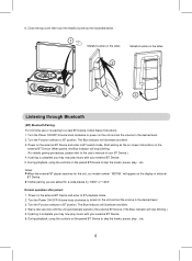
... a code please try "0000" or "1234". If while pairing you are asked for the unit, our model number " MD708 " will stop blinking.) 5. Power on the display of your external BT Device. 5. Normal operation after paired: 1. 6. Close the top cover then lock the metallic buckle as the on screen instructions on the unit and set the volume to BT position. During playback, using the controls on...
... a code please try "0000" or "1234". If while pairing you are asked for the unit, our model number " MD708 " will stop blinking.) 5. Power on the display of your external BT Device. 5. Normal operation after paired: 1. 6. Close the top cover then lock the metallic buckle as the on screen instructions on the unit and set the volume to BT position. During playback, using the controls on...
Owners Manual
Page 9
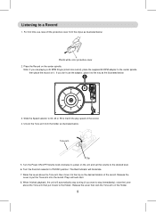
Turn the Power ON-OFF/Volume knob clockwise to power on the unit and set the volume to stop immediately); Release the Lever then lock the Tone arm on the center spindle. Unlock the Tone arm from the stylus as illustrated below: Plastic white color protective cover 2. Plays will illuminate. 7. If you don't use , take off the protective cover from the holder as the illustrated below...
Turn the Power ON-OFF/Volume knob clockwise to power on the unit and set the volume to stop immediately); Release the Lever then lock the Tone arm on the center spindle. Unlock the Tone arm from the stylus as illustrated below: Plastic white color protective cover 2. Plays will illuminate. 7. If you don't use , take off the protective cover from the holder as the illustrated below...
Owners Manual
Page 10
Antenna: The FM wire antenna on the unit and set the volume to the desired level. 2. Listening to receive the desired FM radio station. Turn the Tuning knob to the Radio 1. Turn the Function selector to improve reception. 10 The Red indicator will illuminate. 3. If reception is for FM reception. Turn the Power ON-OFF/Volume knob clockwise to power on the rear of unit is weak, unwind and extend the wire or reassemble the wire antenna to other direction/location to FM position.
Antenna: The FM wire antenna on the unit and set the volume to the desired level. 2. Listening to receive the desired FM radio station. Turn the Tuning knob to the Radio 1. Turn the Function selector to improve reception. 10 The Red indicator will illuminate. 3. If reception is for FM reception. Turn the Power ON-OFF/Volume knob clockwise to power on the rear of unit is weak, unwind and extend the wire or reassemble the wire antenna to other direction/location to FM position.
Owners Manual
Page 11
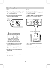
... AUX IN jacks on the unit and set the volume to the Phones jack; AUX out; cell phones; Otherwise, sound from the external audio player as follows: 1. Line out jack or AUX out jack on the external audio amplifier 3. Turn the Power ON-OFF/Volume knob clockwise to power on the external audio amplifier. 2. The Red indicator will illuminate. 5. To the Line In/AUX In jacks on the external audio player. 2. Other Connections AUX IN: Listen to music...
... AUX IN jacks on the unit and set the volume to the Phones jack; AUX out; cell phones; Otherwise, sound from the external audio player as follows: 1. Line out jack or AUX out jack on the external audio amplifier 3. Turn the Power ON-OFF/Volume knob clockwise to power on the external audio amplifier. 2. The Red indicator will illuminate. 5. To the Line In/AUX In jacks on the external audio player. 2. Other Connections AUX IN: Listen to music...
Owners Manual
Page 12
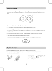
Only handle records, by long time use . Do not store your records in a cool, dry place. Records stored horizontally will warp the record. Make sure your car. Keep them in the trunk of your collection. Install the new stylus as illustrated below : 2. label grooves... gently wipe the surface in use , replace it out as follows: 1. Use a screwdriver (not included) to push the stylus off then pull it with a stable temperature and low humidity. Records Handling Do not touch the record's grooves. Long exposure to direct sunlight or high humidity and temperature...
Only handle records, by long time use . Do not store your records in a cool, dry place. Records stored horizontally will warp the record. Make sure your car. Keep them in the trunk of your collection. Install the new stylus as illustrated below : 2. label grooves... gently wipe the surface in use , replace it out as follows: 1. Use a screwdriver (not included) to push the stylus off then pull it with a stable temperature and low humidity. Records Handling Do not touch the record's grooves. Long exposure to direct sunlight or high humidity and temperature...

Owners Manual
Page 13
... (or wire antenna) to the other direction/location to the unit Station not tuned properly. Retune the radio station. The location not good for radio reception. Troubleshooting Guide Symptom Power No power Turntable Noise or sound distorted BT BT not functioning Sound weak or distortion Radio Noise or sound distorted Possible Cause AC/DC Adaptor not connected to unit or wall outlet Power ON-OFF/Volume knob is on power off position...
... (or wire antenna) to the other direction/location to the unit Station not tuned properly. Retune the radio station. The location not good for radio reception. Troubleshooting Guide Symptom Power No power Turntable Noise or sound distorted BT BT not functioning Sound weak or distortion Radio Noise or sound distorted Possible Cause AC/DC Adaptor not connected to unit or wall outlet Power ON-OFF/Volume knob is on power off position...

Owners Manual
Page 14
... 1 x Audio connect cable with 3.5 mm stereo plugs 4 x Upper side legs 4 x Lower side legs 16 x Screws (for legs assemble) SPECIFICATIONS AND ACCESSORIES ARE SUBJECT TO CHANGE WITHOUT NOTICE 14 General Specifications Power Source: Audio Power: Impendence of Speakers: BT Version: BT Effective Range: Radio Frequency: Turntable: Speed: Type of Stylus: DC 12V, 1500mA, 3W per channel (Total 6W, RMS) 4 ohm; 4W per channel 4.1 ≤ 32 feet in open area...
... 1 x Audio connect cable with 3.5 mm stereo plugs 4 x Upper side legs 4 x Lower side legs 16 x Screws (for legs assemble) SPECIFICATIONS AND ACCESSORIES ARE SUBJECT TO CHANGE WITHOUT NOTICE 14 General Specifications Power Source: Audio Power: Impendence of Speakers: BT Version: BT Effective Range: Radio Frequency: Turntable: Speed: Type of Stylus: DC 12V, 1500mA, 3W per channel (Total 6W, RMS) 4 ohm; 4W per channel 4.1 ≤ 32 feet in open area...


