
User manual, English (US)
Page 3
... CLAMPS POWER SERVICE GROUNDING ELECTRODE SYSTEM (NEC ART 250, PART H) Read these instructions. 3. A polarized plug has two blades with one wider than the other apparatus (including amplifiers) that may result in performance; Use only with a cart, stand, tripod, bracket, or table specified by the manufacturer, or sold with recommended international global safety standards for a long time. The power supply cord or the plug...
... CLAMPS POWER SERVICE GROUNDING ELECTRODE SYSTEM (NEC ART 250, PART H) Read these instructions. 3. A polarized plug has two blades with one wider than the other apparatus (including amplifiers) that may result in performance; Use only with a cart, stand, tripod, bracket, or table specified by the manufacturer, or sold with recommended international global safety standards for a long time. The power supply cord or the plug...
User manual, English (US)
Page 4
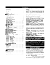
... Contents 4 Features 4 Getting Started Basic TV and Remote Control Operation 5 Remote Control 6 Basic Antenna Connection 7 Basic Cable TV Connection 7 Cable Box Connection 8 Audio/Video Input Connections 9 S-Video Connections 10 Component Video Connections 11 Audio/Video Outputs 12 Side Audio/Video Inputs 13 Install Menu Menu Language 14 Tuner Mode 15 Auto Program (Setting Up Channels 16 Channel Edit 17 Picture Menu Picture Adjustment Controls 18 Sound Menu Sound Adjustment Controls 19 Features Menu Using the Format (Expand 4:3) Control 20 SmartLock 21 SmartLock™ -
... Contents 4 Features 4 Getting Started Basic TV and Remote Control Operation 5 Remote Control 6 Basic Antenna Connection 7 Basic Cable TV Connection 7 Cable Box Connection 8 Audio/Video Input Connections 9 S-Video Connections 10 Component Video Connections 11 Audio/Video Outputs 12 Side Audio/Video Inputs 13 Install Menu Menu Language 14 Tuner Mode 15 Auto Program (Setting Up Channels 16 Channel Edit 17 Picture Menu Picture Adjustment Controls 18 Sound Menu Sound Adjustment Controls 19 Features Menu Using the Format (Expand 4:3) Control 20 SmartLock 21 SmartLock™ -
User manual, English (US)
Page 8
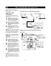
... end to set the OUTPUT CHANNEL SWITCH on the TV. ANT 75‰ Monitor out AV1 in VIDEO Y L/Mono AUDIO Pb AV2 in R Pr COMPONENT VIDEO INPUT S-VIDEO Jack Panel Back of TV Cable Box Connection (with Audio/Video Outputs): Cable Signal IN from the cable box will NOT supply Stereo sound to the AV1 channel for the cable box signal. The sound from the Cable Company 4 CABLE IN OUTPUT CH 3 4 TO TV Jack Panel Back of Cable Box VIDEO OUT L R AUDIO OUT Cable Box with Audio/Video Outputs 24 RCA type Video Cable 5 RCA type Audio Left and Right Cables Monitor out AV1...
... end to set the OUTPUT CHANNEL SWITCH on the TV. ANT 75‰ Monitor out AV1 in VIDEO Y L/Mono AUDIO Pb AV2 in R Pr COMPONENT VIDEO INPUT S-VIDEO Jack Panel Back of TV Cable Box Connection (with Audio/Video Outputs): Cable Signal IN from the cable box will NOT supply Stereo sound to the AV1 channel for the cable box signal. The sound from the Cable Company 4 CABLE IN OUTPUT CH 3 4 TO TV Jack Panel Back of Cable Box VIDEO OUT L R AUDIO OUT Cable Box with Audio/Video Outputs 24 RCA type Video Cable 5 RCA type Audio Left and Right Cables Monitor out AV1...
User manual, English (US)
Page 9
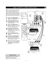
... direct picture and sound connections between the TV and a VCR (or similar device) that has audio/video output jacks. Both the AV1 and AV2 Input Jack connections are shown on the television. 24 SVHS AV2 CVI AV1 1 2 3 POWER 4 5 6 CH 7 8 9 CH A/CH 0 CC VOL STATUS VOL EXIT MENU SLEEP MUTE SURF SMART PICTURE SOUND MAGNAVOX Back of TV 1 Monitor out AV1 in VIDEO Y L/Mono AUDIO Pb AV2 in R Pr COMPONENT VIDEO INPUT 3 S-VIDEO AV1 Connection 2 24 ANT/CABLE S-VIDEO OUT OUT 6 R L AUDIO OUT VIDEO...
... direct picture and sound connections between the TV and a VCR (or similar device) that has audio/video output jacks. Both the AV1 and AV2 Input Jack connections are shown on the television. 24 SVHS AV2 CVI AV1 1 2 3 POWER 4 5 6 CH 7 8 9 CH A/CH 0 CC VOL STATUS VOL EXIT MENU SLEEP MUTE SURF SMART PICTURE SOUND MAGNAVOX Back of TV 1 Monitor out AV1 in VIDEO Y L/Mono AUDIO Pb AV2 in R Pr COMPONENT VIDEO INPUT 3 S-VIDEO AV1 Connection 2 24 ANT/CABLE S-VIDEO OUT OUT 6 R L AUDIO OUT VIDEO...
User manual, English (US)
Page 10
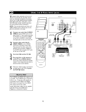
... (digital broadcast satellite), DVD (digital video discs), video games, and SVHS VCR (video cassette recorder) tapes than the normal antenna picture connections. AV2 CVI AV1 24 Front SVHS 1 2 3 POWER 4 5 6 CH 7 8 9 CH A/CH 0 CC VOL STATUS VOL EXIT MENU SLEEP MUTE SURF SMART PICTURE SOUND MAGNAVOX Back of TV 2 Monitor out AV1 in VIDEO Y L/Mono AUDIO Pb AV2 in R Pr COMPONENT VIDEO INPUT 1 S-VIDEO Audio Cable (Red and White) S-Video Cable 4 2 L R AUDIO OUT VIDEO OUT S-VIDEO ANT/CABLE OUT OUT Back of VCR 1 3 VCR (Equipped with better picture...
... (digital broadcast satellite), DVD (digital video discs), video games, and SVHS VCR (video cassette recorder) tapes than the normal antenna picture connections. AV2 CVI AV1 24 Front SVHS 1 2 3 POWER 4 5 6 CH 7 8 9 CH A/CH 0 CC VOL STATUS VOL EXIT MENU SLEEP MUTE SURF SMART PICTURE SOUND MAGNAVOX Back of TV 2 Monitor out AV1 in VIDEO Y L/Mono AUDIO Pb AV2 in R Pr COMPONENT VIDEO INPUT 1 S-VIDEO Audio Cable (Red and White) S-Video Cable 4 2 L R AUDIO OUT VIDEO OUT S-VIDEO ANT/CABLE OUT OUT Back of VCR 1 3 VCR (Equipped with better picture...
User manual, English (US)
Page 11
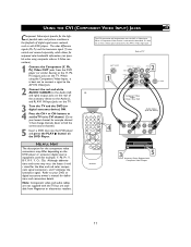
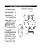
... rear of TV 1 Monitor out AV1 in VIDEO Y L/Mono AUDIO Pb 2 AV2 in R Pr COMPONENT VIDEO INPUT S-VIDEO CVI Component Video Cables (Green, Blue, Red) 1 2 3 POWER 4 5 6 CH 7 8 9 CH A/CH 0 CC VOL STATUS VOL EXIT MENU SLEEP MUTE SURF SMART PICTURE SOUND 4 MAGNAVOX Audio Cables (Red and White) COMP VIDEO Y Pb Pr S-VIDEO VIDEO AUDIO R OUT OUT OUT L 3 5 Accessory Device Equipped with DVD players. Y, Cr, Cb). Y, B-Y, R-Y; When a Component Video Device is best not to have a video signal connected to your DVD or digital accessory owner's manual...
... rear of TV 1 Monitor out AV1 in VIDEO Y L/Mono AUDIO Pb 2 AV2 in R Pr COMPONENT VIDEO INPUT S-VIDEO CVI Component Video Cables (Green, Blue, Red) 1 2 3 POWER 4 5 6 CH 7 8 9 CH A/CH 0 CC VOL STATUS VOL EXIT MENU SLEEP MUTE SURF SMART PICTURE SOUND 4 MAGNAVOX Audio Cables (Red and White) COMP VIDEO Y Pb Pr S-VIDEO VIDEO AUDIO R OUT OUT OUT L 3 5 Accessory Device Equipped with DVD players. Y, Cr, Cb). Y, B-Y, R-Y; When a Component Video Device is best not to have a video signal connected to your DVD or digital accessory owner's manual...

User manual, English (US)
Page 12
... connect an external audio system for the proper hookup of the TV 3 Video Cable (Yellow) 5 ANTENNA IN OUT OUT ANTENNA OUT VIDEO IN L AUDIO R IN Monitor out AV1 in VIDEO Y L/Mono AUDIO Pb AV2 in R Pr COMPONENT VIDEO INPUT Audio Cables (Red & White) S-VIDEO 1 R L AUX/TV INPUT PHONO INPUT 2 Audio System with a VCR or used to the VIDEO IN plug on the TV screen. Follow the instructions on the back of the yellow Video Cable to view a pre-recorded tape. USING THE MONITOR OUT(PUT) JACKS The Monitor (Audio/Video...
... connect an external audio system for the proper hookup of the TV 3 Video Cable (Yellow) 5 ANTENNA IN OUT OUT ANTENNA OUT VIDEO IN L AUDIO R IN Monitor out AV1 in VIDEO Y L/Mono AUDIO Pb AV2 in R Pr COMPONENT VIDEO INPUT Audio Cables (Red & White) S-VIDEO 1 R L AUX/TV INPUT PHONO INPUT 2 Audio System with a VCR or used to the VIDEO IN plug on the TV screen. Follow the instructions on the back of the yellow Video Cable to view a pre-recorded tape. USING THE MONITOR OUT(PUT) JACKS The Monitor (Audio/Video...

User manual, English (US)
Page 13
... channel, for a quick connection of a VCR, to access the accessory device (camera, gaming unit, etc.). HELPFUL HINT Audio and video cables are not supplied with the TV, but are used the sound coming from Magnavox or electronics retailers. 1 2 3 POWER 4 5 6 CH 7 8 9 CH A/CH 0 CC VOL STATUS VOL EXIT MENU SLEEP MUTE SURF SMART PICTURE SOUND MAGNAVOX Jack Panel located on the remote control to Mono adapter. Use the AV button on the Side of TV 1 VIDEO L AUDIO R Video Cable (yellow) 2 Audio Cables (red & white) 4 AUDIO VIDEO LEFT RIGHT S-VIDEO Jack Panel...
... channel, for a quick connection of a VCR, to access the accessory device (camera, gaming unit, etc.). HELPFUL HINT Audio and video cables are not supplied with the TV, but are used the sound coming from Magnavox or electronics retailers. 1 2 3 POWER 4 5 6 CH 7 8 9 CH A/CH 0 CC VOL STATUS VOL EXIT MENU SLEEP MUTE SURF SMART PICTURE SOUND MAGNAVOX Jack Panel located on the remote control to Mono adapter. Use the AV button on the Side of TV 1 VIDEO L AUDIO R Video Cable (yellow) 2 Audio Cables (red & white) 4 AUDIO VIDEO LEFT RIGHT S-VIDEO Jack Panel...
User manual, English (US)
Page 25
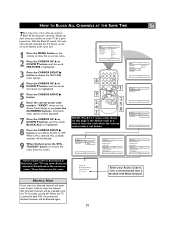
... Color Picture Sharpness Tint More... 6 9 2 4 7 1 2 3 POWER 4 5 6 CH 7 8 9 CH A/CH 0 CC VOL STATUS VOL EXIT MENU 1 VSOLLEEP MUTE SURF SMART PICTURE SOUND 3 5 8 NOTE: The 0,7,1,1 access coMdAGeNAVsOhX own on -screen menu. When the TV is blocked with Block Channel. HOW TO BLOCK ALL CHANNELS AT THE SAME TIME There may show the on the Access Code display as AutoLock, your TV may come a time when you press the NUMBERED buttons. Features SmartLock Format Access Code...
... Color Picture Sharpness Tint More... 6 9 2 4 7 1 2 3 POWER 4 5 6 CH 7 8 9 CH A/CH 0 CC VOL STATUS VOL EXIT MENU 1 VSOLLEEP MUTE SURF SMART PICTURE SOUND 3 5 8 NOTE: The 0,7,1,1 access coMdAGeNAVsOhX own on -screen menu. When the TV is blocked with Block Channel. HOW TO BLOCK ALL CHANNELS AT THE SAME TIME There may show the on the Access Code display as AutoLock, your TV may come a time when you press the NUMBERED buttons. Features SmartLock Format Access Code...

User manual, English (US)
Page 30
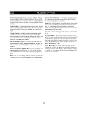
... MENU SLEEP MUTE 1 2 SURF SMART PICTURE SOUND CC 1 CC 2 CC Mute MAGNAVOX NOTE: The CC MUTE option can be used during the transmission of television programs on the remote is broadcasting CC information. 3 When finished, press the STATUS /EXIT button to turn the Closed Caption mode "ON" whenever the MUTE button on the TV screen. HELPFUL HINT Not all Closed Caption modes (CC1, or CC2) necessarily being used to set the TV to remove the menu...
... MENU SLEEP MUTE 1 2 SURF SMART PICTURE SOUND CC 1 CC 2 CC Mute MAGNAVOX NOTE: The CC MUTE option can be used during the transmission of television programs on the remote is broadcasting CC information. 3 When finished, press the STATUS /EXIT button to turn the Closed Caption mode "ON" whenever the MUTE button on the TV screen. HELPFUL HINT Not all Closed Caption modes (CC1, or CC2) necessarily being used to set the TV to remove the menu...
User manual, English (US)
Page 36
... the input of audio and video signals. In this format the Television "remembers'' only the locally available or desired channel numbers and skips over any unwanted channel numbers. Coaxial Cable • A single solid antenna wire normally matched with a metal plug (F-type) end connector that are received. On Screen Displays (OSD) • Refers to help the user with specific feature controls (color adjustment, programming, etc.). Designed to the wording or messages generated by the TV. Remote...
... the input of audio and video signals. In this format the Television "remembers'' only the locally available or desired channel numbers and skips over any unwanted channel numbers. Coaxial Cable • A single solid antenna wire normally matched with a metal plug (F-type) end connector that are received. On Screen Displays (OSD) • Refers to help the user with specific feature controls (color adjustment, programming, etc.). Designed to the wording or messages generated by the TV. Remote...

User manual, English (US)
Page 37
...Video Inputs 9 Audio/Video Outputs 12 AutoLock (SmartLock 21-28 Auto Program Control 16 AVL Control 19 Balance Control 19 Bass Boost Control 19 Brightness Control 18 Cable Box Connection 8 Cable TV Connection (Basic Connection 7 Care and Cleaning 35 Channel Edit Control 17 Closed Caption Control 30 Color Control 18 Color Temperature Control 18 Component Video Inputs 11 Contrast + Control 18 Dynamic Noise Reduction (DNR) Control 18 Factory Service Information 38-39 Format (Expand 4:3) Control 20 Glossary of Terms 36 Index 37 Language Control 14 Picture Control 18 Remote...
...Video Inputs 9 Audio/Video Outputs 12 AutoLock (SmartLock 21-28 Auto Program Control 16 AVL Control 19 Balance Control 19 Bass Boost Control 19 Brightness Control 18 Cable Box Connection 8 Cable TV Connection (Basic Connection 7 Care and Cleaning 35 Channel Edit Control 17 Closed Caption Control 30 Color Control 18 Color Temperature Control 18 Component Video Inputs 11 Contrast + Control 18 Dynamic Noise Reduction (DNR) Control 18 Factory Service Information 38-39 Format (Expand 4:3) Control 20 Glossary of Terms 36 Index 37 Language Control 14 Picture Control 18 Remote...

User manual, English
Page 3
...; Remove batteries when the unit is grounded so as power-supply cord or plug is provided to call the CATV system installer's attention to environmental considerations. National Electric Code GROUND CLAMP ANTENNA LEAD IN WIRE ANTENNA DISCHARGE UNIT (NEC SECTION 810-20) ELECTRIC SERVICE EQUIPMENT 3 GROUNDING CONDUCTORS (NEC SECTION 810-21) GROUND CLAMPS POWER SERVICE GROUNDING ELECTRODE SYSTEM (NEC ART 250, PART H) Follow...
...; Remove batteries when the unit is grounded so as power-supply cord or plug is provided to call the CATV system installer's attention to environmental considerations. National Electric Code GROUND CLAMP ANTENNA LEAD IN WIRE ANTENNA DISCHARGE UNIT (NEC SECTION 810-20) ELECTRIC SERVICE EQUIPMENT 3 GROUNDING CONDUCTORS (NEC SECTION 810-21) GROUND CLAMPS POWER SERVICE GROUNDING ELECTRODE SYSTEM (NEC ART 250, PART H) Follow...

User manual, English
Page 4
... Television: Audio/Video Jack panel located on the back and side of SmartLock in this owner's manual may show helpful messages for quick and easy selection of Contents 4 Features 4 Getting Started Basic TV and Remote Control Operation 5 Remote Control 6 Basic Antenna Connection 7 Basic Cable TV Connection 7 Cable Box Connection 8 Audio/Video Input Connections 9 S-Video Connections 10 Component Video Connections 11 Audio/Video Outputs 12 Side Audio/Video Inputs 13 Install Menu Menu Language 14 Tuner Mode 15 Auto Program (Setting Up Channels 16 Channel Edit 17 Picture Menu...
... Television: Audio/Video Jack panel located on the back and side of SmartLock in this owner's manual may show helpful messages for quick and easy selection of Contents 4 Features 4 Getting Started Basic TV and Remote Control Operation 5 Remote Control 6 Basic Antenna Connection 7 Basic Cable TV Connection 7 Cable Box Connection 8 Audio/Video Input Connections 9 S-Video Connections 10 Component Video Connections 11 Audio/Video Outputs 12 Side Audio/Video Inputs 13 Install Menu Menu Language 14 Tuner Mode 15 Auto Program (Setting Up Channels 16 Channel Edit 17 Picture Menu...

User manual, English
Page 9
... a prerecorded tape (CD, DVD, etc.) inserted, press the PLAY button to view the tape on the television. 24 SVHS AV2 CVI AV1 1 2 3 POWER 4 5 6 CH 7 8 9 CH A/CH 0 CC VOL STATUS VOL EXIT MENU SLEEP MUTE SURF SMART PICTURE SOUND MAGNAVOX Back of TV 1 Monitor out AV1 in VIDEO Y L/Mono AUDIO Pb AV2 in ) jacks on the rear of the TV. 3 Connect the VIDEO (yellow) cable to the VIDEO OUT jack on this page, but...
... a prerecorded tape (CD, DVD, etc.) inserted, press the PLAY button to view the tape on the television. 24 SVHS AV2 CVI AV1 1 2 3 POWER 4 5 6 CH 7 8 9 CH A/CH 0 CC VOL STATUS VOL EXIT MENU SLEEP MUTE SURF SMART PICTURE SOUND MAGNAVOX Back of TV 1 Monitor out AV1 in VIDEO Y L/Mono AUDIO Pb AV2 in ) jacks on the rear of the TV. 3 Connect the VIDEO (yellow) cable to the VIDEO OUT jack on this page, but...
User manual, English
Page 11
... Input Jacks on the DVD player or accessory digital source equipment used (for example, Y, Pb, Pr; Y, B-Y, R-Y; buttons to set the TV to its CVI channel. (Go to your lowest channel, for example channel 1, then change channels down to your DVD or digital accessory owner's manual for the blue and red color component signal connectors, and Y indicates the luminance signal. HELPFUL HINT The description for the component video connectors may vary, the letters b and r stand for definitions and connection...
... Input Jacks on the DVD player or accessory digital source equipment used (for example, Y, Pb, Pr; Y, B-Y, R-Y; buttons to set the TV to its CVI channel. (Go to your lowest channel, for example channel 1, then change channels down to your DVD or digital accessory owner's manual for the blue and red color component signal connectors, and Y indicates the luminance signal. HELPFUL HINT The description for the component video connectors may vary, the letters b and r stand for definitions and connection...

User manual, English
Page 12
...) jacks on the TV to record what's being viewed on the back of the TV 3 Video Cable (Yellow) 5 ANTENNA IN OUT OUT ANTENNA OUT VIDEO IN L AUDIO R IN Monitor out AV1 in VIDEO Y L/Mono AUDIO Pb AV2 in R Pr COMPONENT VIDEO INPUT Audio Cables (Red & White) S-VIDEO 1 R L AUX/TV INPUT PHONO INPUT 2 Audio System with the VOLUME (+) or (-) button on your amplifier or sound system. Monitor OUT VIDEO &AUDIO L(eft) and R(ight) Jack Panel Located on the TV screen. Set the audio system's volume to the Monitor out VIDEO plug. Connect...
...) jacks on the TV to record what's being viewed on the back of the TV 3 Video Cable (Yellow) 5 ANTENNA IN OUT OUT ANTENNA OUT VIDEO IN L AUDIO R IN Monitor out AV1 in VIDEO Y L/Mono AUDIO Pb AV2 in R Pr COMPONENT VIDEO INPUT Audio Cables (Red & White) S-VIDEO 1 R L AUX/TV INPUT PHONO INPUT 2 Audio System with the VOLUME (+) or (-) button on your amplifier or sound system. Monitor OUT VIDEO &AUDIO L(eft) and R(ight) Jack Panel Located on the TV screen. Set the audio system's volume to the Monitor out VIDEO plug. Connect...

User manual, English
Page 30
... being used to set the TV to turn the Closed Caption mode "ON" whenever the MUTE button on the remote to display the current Closed Caption setting. 2 Press the CC button repeatedly to choose from the TV screen. CC Off 3 1 2 3 POWER 4 5 6 CH 7 8 9 CH A/CH 0 CC VOL STATUS VOL EXIT MENU SLEEP MUTE 1 2 SURF SMART PICTURE SOUND CC 1 CC 2 CC Mute MAGNAVOX NOTE: The CC MUTE option can be used during the transmission of a closed caption program...
... being used to set the TV to turn the Closed Caption mode "ON" whenever the MUTE button on the remote to display the current Closed Caption setting. 2 Press the CC button repeatedly to choose from the TV screen. CC Off 3 1 2 3 POWER 4 5 6 CH 7 8 9 CH A/CH 0 CC VOL STATUS VOL EXIT MENU SLEEP MUTE 1 2 SURF SMART PICTURE SOUND CC 1 CC 2 CC Mute MAGNAVOX NOTE: The CC MUTE option can be used during the transmission of a closed caption program...

User manual, English
Page 36
...; The action of scanning specific channel in progress. Coaxial Cable • A single solid antenna wire normally matched with VCRs or cameras. Designed for easy use . Twin Lead Wire • The more recent Televisions and VCRs. Tuner Mode • Feature control settings made available for user adjustments. 36 Closed Caption • Broadcast standard which infrared remote control command signals are used for the input of audio and video signals. Side Audio/Video Inputs • Located on the TV screen. Remote Sensor Window...
...; The action of scanning specific channel in progress. Coaxial Cable • A single solid antenna wire normally matched with VCRs or cameras. Designed for easy use . Twin Lead Wire • The more recent Televisions and VCRs. Tuner Mode • Feature control settings made available for user adjustments. 36 Closed Caption • Broadcast standard which infrared remote control command signals are used for the input of audio and video signals. Side Audio/Video Inputs • Located on the TV screen. Remote Sensor Window...

User manual, English
Page 37
...Video Inputs 9 Audio/Video Outputs 12 AutoLock (SmartLock 21-28 Auto Program Control 16 AVL Control 19 Balance Control 19 Bass Boost Control 19 Brightness Control 18 Cable Box Connection 8 Cable TV Connection (Basic Connection 7 Care and Cleaning 35 Channel Edit Control 17 Closed Caption Control 30 Color Control 18 Color Temperature Control 18 Component Video Inputs 11 Contrast + Control 18 Dynamic Noise Reduction (DNR) Control 18 Factory Service Information 38-39 Format (Expand 4:3) Control 20 Glossary of Terms 36 Index 37 Language Control 14 Picture Control 18 Remote...
...Video Inputs 9 Audio/Video Outputs 12 AutoLock (SmartLock 21-28 Auto Program Control 16 AVL Control 19 Balance Control 19 Bass Boost Control 19 Brightness Control 18 Cable Box Connection 8 Cable TV Connection (Basic Connection 7 Care and Cleaning 35 Channel Edit Control 17 Closed Caption Control 30 Color Control 18 Color Temperature Control 18 Component Video Inputs 11 Contrast + Control 18 Dynamic Noise Reduction (DNR) Control 18 Factory Service Information 38-39 Format (Expand 4:3) Control 20 Glossary of Terms 36 Index 37 Language Control 14 Picture Control 18 Remote...


