User Guide
Page 3
... All trademarks are the properties of Intel Corporation. AMI® is a registered trademark of Novell, Inc. Visit the MSI website for further guidance. Our products are registered trademarks of their respective owners. Intel® and Pentium® are...guide, BIOS updates, driver updates, and other information: http://www.msi.com.tw/program/service/faq/ faq/esc_faq_list.php Contact our technical staff at: support@msi.com.tw iii Netware® is a registered trademark of American Megatrends Inc. Revision History Revision V1.2 Revision History First release for PT880 Neo (V2...
... All trademarks are the properties of Intel Corporation. AMI® is a registered trademark of Novell, Inc. Visit the MSI website for further guidance. Our products are registered trademarks of their respective owners. Intel® and Pentium® are...guide, BIOS updates, driver updates, and other information: http://www.msi.com.tw/program/service/faq/ faq/esc_faq_list.php Contact our technical staff at: support@msi.com.tw iii Netware® is a registered trademark of American Megatrends Inc. Revision History Revision V1.2 Revision History First release for PT880 Neo (V2...
User Guide
Page 5
... Installing the CPU Fan 2-5 Memory ...2-7 Memory Population Rules 2-7 Installing DDR Modules 2-8 Power Supply ...2-9 ATX 20-Pin Power Connector: ATX1 2-9 ATX 12V Power Connector: JPW1 2-9 Back Panel ...2-10 Floppy Disk Drive Connector: FDD1 2-11 ATA133 Hard ...Power Connector: CPUFA1 2-13 v Getting Started 1-1 Mainboard Specifications 1-2 Mainboard Layout 1-4 MSI Special Features 1-5 Color Management 1-5 CoreCenter 1-6 Core CellTM Chip 1-8 Round Cable (Optional 1-9 CPU Thermal Protection 1-9 Live BIOS™/Live Driver 1-11 Live Monitor 1-11 D-Bracket™ 2 (Optional 1-12 ...
... Installing the CPU Fan 2-5 Memory ...2-7 Memory Population Rules 2-7 Installing DDR Modules 2-8 Power Supply ...2-9 ATX 20-Pin Power Connector: ATX1 2-9 ATX 12V Power Connector: JPW1 2-9 Back Panel ...2-10 Floppy Disk Drive Connector: FDD1 2-11 ATA133 Hard ...Power Connector: CPUFA1 2-13 v Getting Started 1-1 Mainboard Specifications 1-2 Mainboard Layout 1-4 MSI Special Features 1-5 Color Management 1-5 CoreCenter 1-6 Core CellTM Chip 1-8 Round Cable (Optional 1-9 CPU Thermal Protection 1-9 Live BIOS™/Live Driver 1-11 Live Monitor 1-11 D-Bracket™ 2 (Optional 1-12 ...
User Guide
Page 6
... Request Routing 2-19 AGP (Accelerated Graphics Port) Slot 2-19 PCI (Peripheral Component Interconnect) Slots 2-19 Chapter 3. BIOS Setup 3-1 Entering Setup ...3-2 Selecting the First Boot Device 3-2 Getting Help 3-3 Control Keys 3-3 The Main Menu ...3-4 Standard CMOS Features 3-6 Advanced... BIOS Features 3-8 Advanced Chipset Features 3-11 Power Management Setup 3-15 PNP/PCI Configurations 3-18 Integrated Peripherals 3-20 PC Health Status ...
... Request Routing 2-19 AGP (Accelerated Graphics Port) Slot 2-19 PCI (Peripheral Component Interconnect) Slots 2-19 Chapter 3. BIOS Setup 3-1 Entering Setup ...3-2 Selecting the First Boot Device 3-2 Getting Help 3-3 Control Keys 3-3 The Main Menu ...3-4 Standard CMOS Features 3-6 Advanced... BIOS Features 3-8 Advanced Chipset Features 3-11 Power Management Setup 3-15 PNP/PCI Configurations 3-18 Integrated Peripherals 3-20 PC Health Status ...

User Guide
Page 7
Channel Audio Function A-7 Appendix B: VIA VT8237 Serial ATA RAID B-1 Introduction ...B-2 BIOS Configuration B-4 Installing RAID Software & Drivers B-14 Using VIA RAID Tool B-17 vii Information A-6 Using 2-, 4- & 6-
Channel Audio Function A-7 Appendix B: VIA VT8237 Serial ATA RAID B-1 Introduction ...B-2 BIOS Configuration B-4 Installing RAID Software & Drivers B-14 Using VIA RAID Tool B-17 vii Information A-6 Using 2-, 4- & 6-
User Guide
Page 10
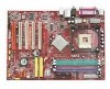
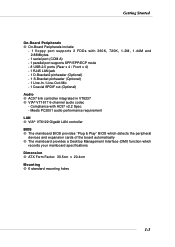
... 6-channel audio codec - Meets PC2001 audio performance requirement LAN h VIA® VT6122 Gigabit LAN controller BIOS h The mainboard BIOS provides "Plug & Play" BIOS which detects the peripheral devices and expansion cards of the board automatically h The mainboard provides a Desktop ...Management Interface (DMI) function which records your mainboard specifications Dimension h ATX Form Factor: 30.5cm x 20.4cm Mounting h 6 standard ...
... 6-channel audio codec - Meets PC2001 audio performance requirement LAN h VIA® VT6122 Gigabit LAN controller BIOS h The mainboard BIOS provides "Plug & Play" BIOS which detects the peripheral devices and expansion cards of the board automatically h The mainboard provides a Desktop ...Management Interface (DMI) function which records your mainboard specifications Dimension h ATX Form Factor: 30.5cm x 20.4cm Mounting h 6 standard ...
User Guide
Page 14
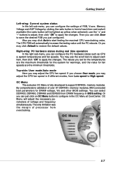
... bars to adjust each item and make it available (the radio button will adjust the necessary parameters of over 67 DDR400+ memory modules, MSI concluded best parameters for fan speeds are the maximum thresholds for the system for warnings, and the value for DRAM voltage, Vio and other...support DDR400+ memory modules. By comprehensive validation of voltage and frequency simultaneously. The only limitation was the margin of processor from DRAM frequency in BIOS setting. Then you can click Save to High speed. OC Menu The exclusive OC Menu is fully developed to configure in the OC Menu ...
... bars to adjust each item and make it available (the radio button will adjust the necessary parameters of over 67 DDR400+ memory modules, MSI concluded best parameters for fan speeds are the maximum thresholds for the system for warnings, and the value for DRAM voltage, Vio and other...support DDR400+ memory modules. By comprehensive validation of voltage and frequency simultaneously. The only limitation was the margin of processor from DRAM frequency in BIOS setting. Then you can click Save to High speed. OC Menu The exclusive OC Menu is fully developed to configure in the OC Menu ...
User Guide
Page 17
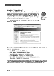
... the screen. To use the function, you don't need to search for the correct BIOS/driver version throughout the whole Web site. MS-7043 ATX Mainboard Live BIOS™/Live Driver™ The Live BIOS™/Live Driver™ is displayed. Click the desired button to the "Live Update Guide..., a "sorry" message is a tool used to detect and update your BIOS/drivers online so that you need to install the "MSI Live Update 3" application. Updates the VGA BIOS online. Ü Live VGA Driver - After the installation, the "MSI Live Update 3" icon (as shown on the right) will appear: Five ...
... the screen. To use the function, you don't need to search for the correct BIOS/driver version throughout the whole Web site. MS-7043 ATX Mainboard Live BIOS™/Live Driver™ The Live BIOS™/Live Driver™ is displayed. Click the desired button to the "Live Update Guide..., a "sorry" message is a tool used to detect and update your BIOS/drivers online so that you need to install the "MSI Live Update 3" application. Updates the VGA BIOS online. Ü Live VGA Driver - After the installation, the "MSI Live Update 3" icon (as shown on the right) will appear: Five ...

User Guide
Page 18
...Search schedule. To use the function, you to view the last search result if there is any. tions about MSI's products for the BIOS/drivers version, or change the LAN settings right from the MSI Live Monitor [Preference] dialog box . 1-11 z View Last Result - Allows you need immediately. z Preference... Monitor™ application. Searches for the latest BIOS/drivers version on the screen. If Preference is a tool used to schedule the search for the BIOS/drivers version you can specify how often the system will appear on the MSI Web site. z FAQ - Getting Started Live...
...Search schedule. To use the function, you to view the last search result if there is any. tions about MSI's products for the BIOS/drivers version, or change the LAN settings right from the MSI Live Monitor [Preference] dialog box . 1-11 z View Last Result - Allows you need immediately. z Preference... Monitor™ application. Searches for the latest BIOS/drivers version on the screen. If Preference is a tool used to schedule the search for the BIOS/drivers version you can specify how often the system will appear on the MSI Web site. z FAQ - Getting Started Live...
User Guide
Page 19
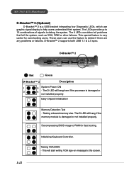
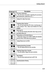
... signals to help users understand their system. The D-LED will start writing VGA sign-on message to RAM for overclocking users. MS-7043 ATX Mainboard D-Bracket™ 2 (Optional) D-Bracket™ 2 is a USB bracket integrating four Diagnostic LEDs, which use the feature to... detect if there are any problems or failures. Initializing Keyboard Controller. Decompressing BIOS image to the screen. 1-12 This will hang here if the processor is damaged or not installed properly. D-Bracket™ 2 1 2 3 4...
... signals to help users understand their system. The D-LED will start writing VGA sign-on message to RAM for overclocking users. MS-7043 ATX Mainboard D-Bracket™ 2 (Optional) D-Bracket™ 2 is a USB bracket integrating four Diagnostic LEDs, which use the feature to... detect if there are any problems or failures. Initializing Keyboard Controller. Decompressing BIOS image to the screen. 1-12 This will hang here if the processor is damaged or not installed properly. D-Bracket™ 2 1 2 3 4...
User Guide
Page 20
... Floppy Drive Controller - Operating System Booting 1-13 Then, detect and initialize the video adapter. This will start showing information about logo, processor brand name, etc... BIOS Sign On - This will initialize Floppy Drive and controller. This will initialize IDE drive and controller. Getting Started D-Bracket™ 2 Description Processor Initialization 1 2 - This will...
... Floppy Drive Controller - Operating System Booting 1-13 Then, detect and initialize the video adapter. This will start showing information about logo, processor brand name, etc... BIOS Sign On - This will initialize Floppy Drive and controller. This will initialize IDE drive and controller. Getting Started D-Bracket™ 2 Description Processor Initialization 1 2 - This will...
User Guide
Page 35
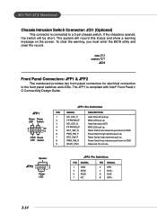
To clear the warning, you must enter the BIOS utility and clear the record. JFP1 Power Power LED Switch 2 10 1 9 HDD Reset LED Switch JFP1 Pin Definition PIN SIGNAL 1 HD_LED_P 2 FP PWR/SLP 3 HD_LED_N 4 .... Speaker JFP2 2 1 8 7 Power LED JFP2 Pin Definition PIN SIGNAL 1 GND 3 SLED 5 PLED 7 NC PIN SIGNAL 2 SPK- 4 BUZ+ 6 BUZ- 8 SPK+ 2-14 Do not use. MS-7043 ATX Mainboard Chassis Intrusion Switch Connector: JCI1 (Optional) This connector is compliant with Intel® Front Panel I/ O Connectivity Design Guide.
To clear the warning, you must enter the BIOS utility and clear the record. JFP1 Power Power LED Switch 2 10 1 9 HDD Reset LED Switch JFP1 Pin Definition PIN SIGNAL 1 HD_LED_P 2 FP PWR/SLP 3 HD_LED_N 4 .... Speaker JFP2 2 1 8 7 Power LED JFP2 Pin Definition PIN SIGNAL 1 GND 3 SLED 5 PLED 7 NC PIN SIGNAL 2 SPK- 4 BUZ+ 6 BUZ- 8 SPK+ 2-14 Do not use. MS-7043 ATX Mainboard Chassis Intrusion Switch Connector: JCI1 (Optional) This connector is compliant with Intel® Front Panel I/ O Connectivity Design Guide.
User Guide
Page 40
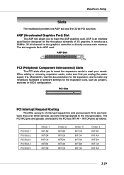
... settings for the throughput demands of interrupt request line and pronounced I-R-Q, are typically connected to the PCI bus INT A# ~ INT D# pins as jumpers, switches or BIOS configuration. The slot supports 8x/4x AGP card. PCI Slot PCI Interrupt Request Routing The IRQ, acronym of 3D graphics. The PCI IRQ pins are...
... settings for the throughput demands of interrupt request line and pronounced I-R-Q, are typically connected to the PCI bus INT A# ~ INT D# pins as jumpers, switches or BIOS configuration. The slot supports 8x/4x AGP card. PCI Slot PCI Interrupt Request Routing The IRQ, acronym of 3D graphics. The PCI IRQ pins are...
User Guide
Page 41
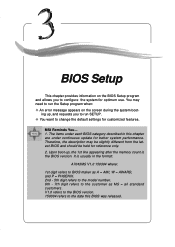
... BIOS was released. 3-1 The items under each BIOS category described in the format: A7043MS V1.0 150304 where: 1st digit refers to BIOS maker... as A = AMI, W = AWARD, and P = PHOENIX. 2nd - 5th digit refers to the model number. 6th - 7th digit refers to configure the system for reference only. 2. BIOS Setup BIOS... Setup This chapter provides information on the screen during the system boot- You may be slightly different from the latest BIOS and should be held for optimum use. It is the BIOS... error message appears on the BIOS Setup program and allows you...
... BIOS was released. 3-1 The items under each BIOS category described in the format: A7043MS V1.0 150304 where: 1st digit refers to BIOS maker... as A = AMI, W = AWARD, and P = PHOENIX. 2nd - 5th digit refers to the model number. 6th - 7th digit refers to configure the system for reference only. 2. BIOS Setup BIOS... Setup This chapter provides information on the screen during the system boot- You may be slightly different from the latest BIOS and should be held for optimum use. It is the BIOS... error message appears on the BIOS Setup program and allows you...
User Guide
Page 42
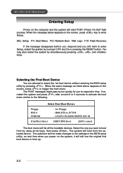
... same message as listed above appears on the screen, press to select the 1st boot device without entering the BIOS setup utility by pressing . Select the one you to respond in the BIOS setup utility, so next time when you still wish to enter Setup, restart the system by turning it will... The boot menu will boot from by using arrow keys, then press . The selection will not make changes to the settings in time. MS-7043 ATX Mainboard Entering Setup Power on the computer and the system will still use the original first boot device to boot from the selected device.
... same message as listed above appears on the screen, press to select the 1st boot device without entering the BIOS setup utility by pressing . Select the one you to respond in the BIOS setup utility, so next time when you still wish to enter Setup, restart the system by turning it will... The boot menu will boot from by using arrow keys, then press . The selection will not make changes to the settings in time. MS-7043 ATX Mainboard Entering Setup Power on the computer and the system will still use the original first boot device to boot from the selected device.
User Guide
Page 43
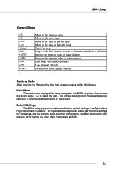
Default Settings The BIOS setup program contains two kinds of the screen. The Optimal Defaults provide stable performance settings for the selected setup category is the ...Defaults Save all devices and the system, while the High Performance Defaults provide the best system performance but may affect the system stability. 3-3 BIOS Setup Control Keys Enter> Move to the previous item Move to the next item Move to the item in the left hand Move to...item Jumps to the Exit menu or returns to select the item. Main Menu The main menu displays the setup categories the BIOS supplies.
Default Settings The BIOS setup program contains two kinds of the screen. The Optimal Defaults provide stable performance settings for the selected setup category is the ...Defaults Save all devices and the system, while the High Performance Defaults provide the best system performance but may affect the system stability. 3-3 BIOS Setup Control Keys Enter> Move to the previous item Move to the next item Move to the item in the left hand Move to...item Jumps to the Exit menu or returns to select the item. Main Menu The main menu displays the setup categories the BIOS supplies.
User Guide
Page 44
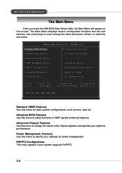
... the sub-menu. Advanced Chipset Features Use this menu to change the values in the chipset registers and optimize your system's performance. Advanced BIOS Features Use this menu to setup the items of AMI® special enhanced features. Power Management Features Use this menu for power management.... MS-7043 ATX Mainboard The Main Menu Once you enter the AMI BIOS New Setup Utility, the Main Menu will appear on the screen. Use arrow keys to move among the items...
... the sub-menu. Advanced Chipset Features Use this menu to change the values in the chipset registers and optimize your system's performance. Advanced BIOS Features Use this menu to setup the items of AMI® special enhanced features. Power Management Features Use this menu for power management.... MS-7043 ATX Mainboard The Main Menu Once you enter the AMI BIOS New Setup Utility, the Main Menu will appear on the screen. Use arrow keys to move among the items...
User Guide
Page 45
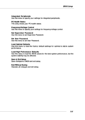
... setup. 3-5 Load Optimal Defaults Use this menu to load the factory default settings for the best system performance, but the system stability may be affected. BIOS Setup Integrated Peripherals Use this menu to specify your settings for frequency/voltage control. Set User Password Use this menu to set User Password. Set...
... setup. 3-5 Load Optimal Defaults Use this menu to load the factory default settings for the best system performance, but the system stability may be affected. BIOS Setup Integrated Peripherals Use this menu to specify your settings for frequency/voltage control. Set User Password Use this menu to set User Password. Set...
User Guide
Page 46
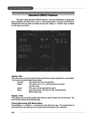
... (usually the current time). System Date This allows you to 31 can be keyed by numeric function keys. [year] The year can be adjusted by BIOS. System Time This allows you to set the system to the date that you want to modify and use the or keys to switch to... Sat, determined by users. [day] Day of hard disk drive will show up on the right hand according to the value you prefer. MS-7043 ATX Mainboard Standard CMOS Features The items inside Standard CMOS Features menu are divided into 8 categories. The format is [hour] [minute] [second]. The specification of the...
... (usually the current time). System Date This allows you to 31 can be keyed by numeric function keys. [year] The year can be adjusted by BIOS. System Time This allows you to set the system to the date that you want to modify and use the or keys to switch to... Sat, determined by users. [day] Day of hard disk drive will show up on the right hand according to the value you prefer. MS-7043 ATX Mainboard Standard CMOS Features The items inside Standard CMOS Features menu are divided into 8 categories. The format is [hour] [minute] [second]. The specification of the...
User Guide
Page 47
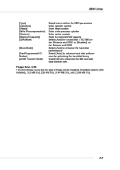
BIOS Setup [Type] [Cylinders] [Heads] [Write Precompensation] [Sectors] [Maximum Capacity] [LBA Mode] [Block Mode] [Fast Programmed I/O Modes] [32 Bit Transfer Mode] Select how to define the ...
BIOS Setup [Type] [Cylinders] [Heads] [Write Precompensation] [Sectors] [Maximum Capacity] [LBA Mode] [Block Mode] [Fast Programmed I/O Modes] [32 Bit Transfer Mode] Select how to define the ...
User Guide
Page 48
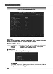
... full screen at boot. [Disabled] Shows the POST messages at boot. Settings are: [Enabled] Shows a still image (logo) on the bootup screen. MS-7043 ATX Mainboard Advanced BIOS Features Quick Boot Setting the item to [Enabled] allows the system to load the operating system. 3-8 Full Screen LOGO Show This item enables you...
... full screen at boot. [Disabled] Shows the POST messages at boot. Settings are: [Enabled] Shows a still image (logo) on the bootup screen. MS-7043 ATX Mainboard Advanced BIOS Features Quick Boot Setting the item to [Enabled] allows the system to load the operating system. 3-8 Full Screen LOGO Show This item enables you...


