User Guide
Page 22
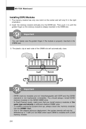
... until the golden finger on the center and will automatically close. DDR2 memory modules are not interchangeable with a 2GB memory module. 2-8 To enable successful system boot-up to 7+GB (not full 8GB) when each side of the same type and density in the right orientation. 2. MS-7320 Mainboard Installing DDR2 Modules...
... until the golden finger on the center and will automatically close. DDR2 memory modules are not interchangeable with a 2GB memory module. 2-8 To enable successful system boot-up to 7+GB (not full 8GB) when each side of the same type and density in the right orientation. 2. MS-7320 Mainboard Installing DDR2 Modules...
User Guide
Page 24
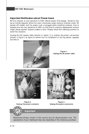
... sensitive to avoid this situation. The appearance of memory-replacement actions might cause system chipset unable to ESD, so this section are very sensitive to boot. Unplug the AC power cable (shown in figure 1) or unplug the power connectors (shown in this kind of your mainboard may vary depending on the...
... sensitive to avoid this situation. The appearance of memory-replacement actions might cause system chipset unable to ESD, so this section are very sensitive to boot. Unplug the AC power cable (shown in figure 1) or unplug the power connectors (shown in this kind of your mainboard may vary depending on the...
User Guide
Page 35
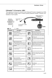
...Testing onboard memory size. tem bus, etc...) 1 2 1 2 Testing RTC (Real Time Clock) Operating System Booting 3 4 3 4 2-21 Hardware Setup D-Bracket™ 2 Connector: JDB1 This connector is for fast booting. 3 4 1 2 Initializing Keyboard Controller. 1 2 Initializing Hard Drive Controller This will initialize IDE drive and... the screen. 3 4 controller. 1 Processor Initialization 2 This will show information regarding 1 2 BootAttempt This will set low stack and boot via 3 4 the processor (like brand name, sys- 3 4 INT 19h. The 1 2 Testing base memory from 240K to ...
...Testing onboard memory size. tem bus, etc...) 1 2 1 2 Testing RTC (Real Time Clock) Operating System Booting 3 4 3 4 2-21 Hardware Setup D-Bracket™ 2 Connector: JDB1 This connector is for fast booting. 3 4 1 2 Initializing Keyboard Controller. 1 2 Initializing Hard Drive Controller This will initialize IDE drive and... the screen. 3 4 controller. 1 Processor Initialization 2 This will show information regarding 1 2 BootAttempt This will set low stack and boot via 3 4 the processor (like brand name, sys- 3 4 INT 19h. The 1 2 Testing base memory from 240K to ...
User Guide
Page 36
SW3 Important Make sure that has a power supply from external battery to keep the system configuration data. With the CMOS RAM, the system can automatically boot OS every time it is a CMOS RAM on . Clear CMOS Button: SW3 There is turned on board that you power off the system before clearing ...CMOS data. 2-22 This section will explain how to change your motherboard's function through the use the button to clear data. If you to set the computer's function. Press the button to clear the data. MS-7320...
SW3 Important Make sure that has a power supply from external battery to keep the system configuration data. With the CMOS RAM, the system can automatically boot OS every time it is a CMOS RAM on . Clear CMOS Button: SW3 There is turned on board that you power off the system before clearing ...CMOS data. 2-22 This section will explain how to change your motherboard's function through the use the button to clear data. If you to set the computer's function. Press the button to clear the data. MS-7320...
User Guide
Page 41
You may need to run the Setup program when: ² An error message appears on the BIOS Setup program and allows you to run SETUP. ² You want to configure the system for customized features. 3-1 Chapter 3 BIOS Setup BIOS Setup This chapter provides information on the screen during the system booting up, and requests you to change the default settings for optimum use.
You may need to run the Setup program when: ² An error message appears on the BIOS Setup program and allows you to run SETUP. ² You want to configure the system for customized features. 3-1 Chapter 3 BIOS Setup BIOS Setup This chapter provides information on the screen during the system booting up, and requests you to change the default settings for optimum use.
User Guide
Page 42
... may be slightly different from the latest BIOS and should be held for better system performance. The items under continuous update for reference only. 2. Upon boot-up, the 1st line appearing after the memory count is usually in this BIOS was released. 3-2 V1.0 refers to the BIOS version. 033007 refers to...
... may be slightly different from the latest BIOS and should be held for better system performance. The items under continuous update for reference only. 2. Upon boot-up, the 1st line appearing after the memory count is usually in this BIOS was released. 3-2 V1.0 refers to the BIOS version. 033007 refers to...
User Guide
Page 48
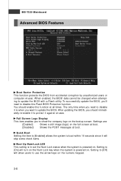
...accidental corruption by unauthorized users or computer viruses. To successfully update the BIOS, you'll need to disable it will skip some check items. Boot Up Num-Lock LED This setting is powered on . Full Screen Logo Display This item enables you want to use the arrow keys on... image (logo) on the numeric keypad. 3-8 Setting to set the Num Lock status when the system is when you to disable this function at boot. The only time when you should enable this Flash BIOS Protection function. You should immediately re-enable it against viruses. Setting to [Off] will ...
...accidental corruption by unauthorized users or computer viruses. To successfully update the BIOS, you'll need to disable it will skip some check items. Boot Up Num-Lock LED This setting is powered on . Full Screen Logo Display This item enables you want to use the arrow keys on... image (logo) on the numeric keypad. 3-8 Setting to set the Num Lock status when the system is when you to disable this function at boot. The only time when you should enable this Flash BIOS Protection function. You should immediately re-enable it against viruses. Setting to [Off] will ...
User Guide
Page 50
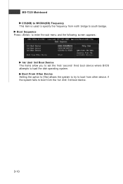
if the system fails to load the disk operating system. Boot Sequence Press to enter the sub-menu and the following screen appears: 1st/ 2nd/ 3rd Boot Device The items allow you to set the first/ second/ third boot device where BIOS attempts to boot from other device. Boot From Other Device Setting the option to [Yes] allows the system to try to south beidge. MS-7320 Mainboard C55(NB) to NVIDIA(SB) Frequency This item is used to specify the frequency from north bridge to boot from the 1st/ 2nd/ 3rd boot device. 3-10
if the system fails to load the disk operating system. Boot Sequence Press to enter the sub-menu and the following screen appears: 1st/ 2nd/ 3rd Boot Device The items allow you to set the first/ second/ third boot device where BIOS attempts to boot from other device. Boot From Other Device Setting the option to [Yes] allows the system to try to south beidge. MS-7320 Mainboard C55(NB) to NVIDIA(SB) Frequency This item is used to specify the frequency from north bridge to boot from the 1st/ 2nd/ 3rd boot device. 3-10
User Guide
Page 51
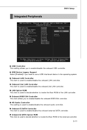
... This item is used to decide whether to enable/disable the onboard USB controller. Onboard IEEE1394 Controller This item allows you to invoke the Boot ROM of the external controller. 3-11 Onboard E-SATA Controller This item is used to enable/disable the onboard 2nd LAN controller. Onboard 2nd... This item is used to decide whether to enable/disable the onboard LAN controller. Onboard LAN Controller This item is used to invoke the Boot ROM of the LAN controller. HD Audio Controller This setting is used to use a USB-interfaced device in the operating system. USB Device...
... This item is used to decide whether to enable/disable the onboard USB controller. Onboard IEEE1394 Controller This item allows you to invoke the Boot ROM of the external controller. 3-11 Onboard E-SATA Controller This item is used to enable/disable the onboard 2nd LAN controller. Onboard 2nd... This item is used to decide whether to enable/disable the onboard LAN controller. Onboard LAN Controller This item is used to invoke the Boot ROM of the LAN controller. HD Audio Controller This setting is used to use a USB-interfaced device in the operating system. USB Device...
User Guide
Page 55
Resume by Onbaord LAN W hen set to [Enabled], the feature allows your system to enable or disable the feature of booting up the system on LAN device. BIOS Setup Resume by RTC Alarm The field is used to be awakened from the power saving modes through any event on a scheduled time/date. 3-15
Resume by Onbaord LAN W hen set to [Enabled], the feature allows your system to enable or disable the feature of booting up the system on LAN device. BIOS Setup Resume by RTC Alarm The field is used to be awakened from the power saving modes through any event on a scheduled time/date. 3-15
User Guide
Page 64
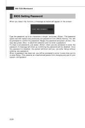
You will boot and you can enter Setup without entering any password. You may also press to six characters in length, and press . Once the password is disabled, ...
You will boot and you can enter Setup without entering any password. You may also press to six characters in length, and press . Once the password is disabled, ...
User Guide
Page 82
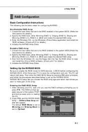
.... 3. Specify the RAID level, either Mirroring (RAID 1), Striping (RAID 0), Striping and Mirroring (RAID 0+1), RAID 5 or JBOD and create the desired RAID array. 3. Boot from the W indows CD, use the floppy disk that are to enable the RAID mode for details.) 4. Initialize the NVRAID Array Disks. The default RAID...details.) 2. After rebooting your PC, wait until you see the RAID software prompting you want to make part of the system POST and boot process prior to be RAID enabled in BIOS before configuring the NVRAID BIOS. Choose the hard disks that has the RAID driver to copy ...
.... 3. Specify the RAID level, either Mirroring (RAID 1), Striping (RAID 0), Striping and Mirroring (RAID 0+1), RAID 5 or JBOD and create the desired RAID array. 3. Boot from the W indows CD, use the floppy disk that are to enable the RAID mode for details.) 4. Initialize the NVRAID Array Disks. The default RAID...details.) 2. After rebooting your PC, wait until you see the RAID software prompting you want to make part of the system POST and boot process prior to be RAID enabled in BIOS before configuring the NVRAID BIOS. Choose the hard disks that has the RAID driver to copy ...
User Guide
Page 86
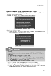
Insert the MSI CD into the CD-ROM drive. 2. The follow the instruction below to a formatted floppy disk. 4. The W indows Setup screen appears as below: Important Please follow - ...\C55+M CP55\IDE\Win XP\sataraid to make an nVIDIA Serial ATA RAID driver for bootable RAID Array) 1. After you complete the RAID BIOS setup, boot from the W indows CD, and the W indows Setup program starts. 2. Specify the NVIDIA drivers: (1) Insert the floppy that has the RAID driver, press S, then press...
Insert the MSI CD into the CD-ROM drive. 2. The follow the instruction below to a formatted floppy disk. 4. The W indows Setup screen appears as below: Important Please follow - ...\C55+M CP55\IDE\Win XP\sataraid to make an nVIDIA Serial ATA RAID driver for bootable RAID Array) 1. After you complete the RAID BIOS setup, boot from the W indows CD, and the W indows Setup program starts. 2. Specify the NVIDIA drivers: (1) Insert the floppy that has the RAID driver, press S, then press...
User Guide
Page 92
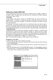
... hard disk is RAID enabled. 2. Enter the RAID BIOS and make sure that the drive that requires a particular disk when one disk is used to boot the OS, two hard drives are set up as a free disk, then if one of the mirrored array drives fails, the free disk will be... and that disk is used by any array (if one free disk. Assigning a Free Disk To mark a disk as a spare drive for a failed disk. B-13 Boot into W indows and run the NVRAIDMAN program.
... hard disk is RAID enabled. 2. Enter the RAID BIOS and make sure that the drive that requires a particular disk when one disk is used to boot the OS, two hard drives are set up as a free disk, then if one of the mirrored array drives fails, the free disk will be... and that disk is used by any array (if one free disk. Assigning a Free Disk To mark a disk as a spare drive for a failed disk. B-13 Boot into W indows and run the NVRAIDMAN program.
User Guide
Page 93
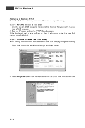
... Disk to an Array W hile running NVRAIDMAN, dedicate the free disk to an array by a specific array, Step 1: Mark the Disk as a Free Disk 1. B-14 Boot into W indows and run the NVRAIDMAN program. MS-7320 Mainboard Assigning a Dedicated Disk To mark a disk as dedicated, or reserve it will appear under the...
... Disk to an Array W hile running NVRAIDMAN, dedicate the free disk to an array by a specific array, Step 1: Mark the Disk as a Free Disk 1. B-14 Boot into W indows and run the NVRAIDMAN program. MS-7320 Mainboard Assigning a Dedicated Disk To mark a disk as dedicated, or reserve it will appear under the...
User Guide
Page 96
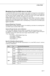
... . General Requirements and Limitations • The new array capacity must be equal to RAID 1 - m =2, n =1 RAID 1 array must back up the data, delete the array, re-boot the PC, and then reconfigure the new array. For example, it is the same size as (or larger than the original array. From RAID 1 to...
... . General Requirements and Limitations • The new array capacity must be equal to RAID 1 - m =2, n =1 RAID 1 array must back up the data, delete the array, re-boot the PC, and then reconfigure the new array. For example, it is the same size as (or larger than the original array. From RAID 1 to...


