User Guide
Page 4
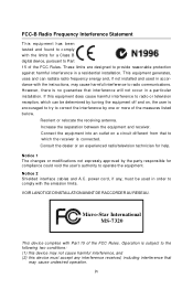
... radiate radio frequency energy and, if not installed and used in order to provide reasonable protection against harmful interference in a particular installation. Micro-Star International MS-7320 This device complies with the instructions, may cause undesired operation. These limits are designed to comply with the emission limits.
... radiate radio frequency energy and, if not installed and used in order to provide reasonable protection against harmful interference in a particular installation. Micro-Star International MS-7320 This device complies with the instructions, may cause undesired operation. These limits are designed to comply with the emission limits.
User Guide
Page 11
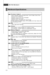
...Sound - SATA6~7 support RAID 0 or RAID 1 mode - Supports Hyper-Threading (HT) Technology (For the latest information about CPU, please visit http://www.msi. Automatic Mirroring under RAID 1 mode (default) 1-2 Core 2 Extreme (dual and quad core), Core 2 Quad, Core 2 Duo, Pentium XE & ...® NF590i SLI (MCP55XE) chipset Memory Support - SATA1~5 support RAID 0 or 1, 0+1, 5 or JBOD mode SiliconImage Sil4723 Hardware RAID - MS-7320 Mainboard Mainboard Specifications Processor Support - Chip integrated by Realtek® RTL8211B phy IEEE 1394 - Supports up to 2 IDE devices SATA - 5 SATA...
...Sound - SATA6~7 support RAID 0 or RAID 1 mode - Supports Hyper-Threading (HT) Technology (For the latest information about CPU, please visit http://www.msi. Automatic Mirroring under RAID 1 mode (default) 1-2 Core 2 Extreme (dual and quad core), Core 2 Quad, Core 2 Duo, Pentium XE & ...® NF590i SLI (MCP55XE) chipset Memory Support - SATA1~5 support RAID 0 or 1, 0+1, 5 or JBOD mode SiliconImage Sil4723 Hardware RAID - MS-7320 Mainboard Mainboard Specifications Processor Support - Chip integrated by Realtek® RTL8211B phy IEEE 1394 - Supports up to 2 IDE devices SATA - 5 SATA...
User Guide
Page 18
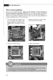
... the CPU & cooler correctly. The availability of socket reveal. 4. The CPU socket has a plastic cap on the top to prevent overheating. Open the load lever. MS-7320 Mainboard CPU & Cooler Installation W hen you install the CPU, always cover it to protect the contact from lever hinge side (as the arrow shows). 3. Meanwhile...
... the CPU & cooler correctly. The availability of socket reveal. 4. The CPU socket has a plastic cap on the top to prevent overheating. Open the load lever. MS-7320 Mainboard CPU & Cooler Installation W hen you install the CPU, always cover it to protect the contact from lever hinge side (as the arrow shows). 3. Meanwhile...
User Guide
Page 20
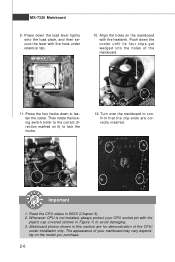
... the load lever lightly onto the load plate, and then secure the lever with the plastic cap covered (shown in Figure 1) to fasten the cooler. MS-7320 Mainboard 9. Then rotate the locking switch (refer to the correct direction marked on it) to confirm that the clip-ends are for demonstration of the...
... the load lever lightly onto the load plate, and then secure the lever with the plastic cap covered (shown in Figure 1) to fasten the cooler. MS-7320 Mainboard 9. Then rotate the locking switch (refer to the correct direction marked on it) to confirm that the clip-ends are for demonstration of the...
User Guide
Page 22
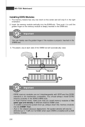
... DIM M1 first. - In Dual-Channel mode, make sure that you install memory modules of the DIMM slot will only fit in the DIMM slot. MS-7320 Mainboard Installing DDR2 Modules 1. Due to 7+GB (not full 8GB) when each side of the same type and density in the DDR2 DIMM slots. - Important...
... DIM M1 first. - In Dual-Channel mode, make sure that you install memory modules of the DIMM slot will only fit in the DIMM slot. MS-7320 Mainboard Installing DDR2 Modules 1. Due to 7+GB (not full 8GB) when each side of the same type and density in the DDR2 DIMM slots. - Important...
User Guide
Page 24
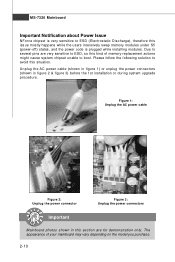
...-off) states, and the power code is very sensitive to avoid this kind of your mainboard may vary depending on the model you purchase. 2-10 MS-7320 Mainboard Important Notification about Power Issue NForce chipset is plugged while installing modules. Due to boot. Unplug the AC power cable (shown in figure 1) or...
...-off) states, and the power code is very sensitive to avoid this kind of your mainboard may vary depending on the model you purchase. 2-10 MS-7320 Mainboard Important Notification about Power Issue NForce chipset is plugged while installing modules. Due to boot. Unplug the AC power cable (shown in figure 1) or...
User Guide
Page 26
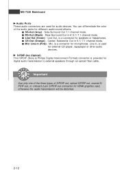
... You can differentiate the color of S/PDIF-out, optical S/PDIF-out, coaxial S/ PDIF-out, or onboard 2-pin S/PDIF-out connector for different audio sound effects. MS-7320 Mainboard Audio Ports These audio connectors are used for microphones.
... You can differentiate the color of S/PDIF-out, optical S/PDIF-out, coaxial S/ PDIF-out, or onboard 2-pin S/PDIF-out connector for different audio sound effects. MS-7320 Mainboard Audio Ports These audio connectors are used for microphones.
User Guide
Page 28
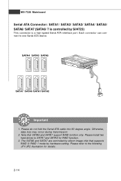
Otherwise, data loss may occur during transmission. 2. Please refer to the following JP1/JP2 illustration for RAID function. 3. MS-7320 Mainboard Serial ATA Connector: SATA1/ SATA2/ SATA3/ SATA4/ SATA5/ SATA6/ SATA7 (SATA6/ 7 is a high-speed Serial ATA interface port. Note that supports RAID 0/ RAID 1 mode ...
Otherwise, data loss may occur during transmission. 2. Please refer to the following JP1/JP2 illustration for RAID function. 3. MS-7320 Mainboard Serial ATA Connector: SATA1/ SATA2/ SATA3/ SATA4/ SATA5/ SATA6/ SATA7 (SATA6/ 7 is a high-speed Serial ATA interface port. Note that supports RAID 0/ RAID 1 mode ...

User Guide
Page 30
Fan/heatsink with 3 or 4 pins are both available for proper CPU cooling fan. 2. MS-7320 Mainboard Fan Power Connectors: CPUFAN1, NBFAN1, SYSFAN1, PWRFAN1 The fan power connectors support system cooling fan with speed sensor to take advantage of the CPU ...
Fan/heatsink with 3 or 4 pins are both available for proper CPU cooling fan. 2. MS-7320 Mainboard Fan Power Connectors: CPUFAN1, NBFAN1, SYSFAN1, PWRFAN1 The fan power connectors support system cooling fan with speed sensor to take advantage of the CPU ...
User Guide
Page 32
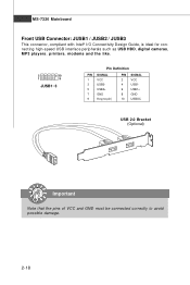
MS-7320 Mainboard Front USB Connector: JUSB1 / JUSB2 / JUSB3 This connector, compliant with Intel® I/O Connectivity Design Guide, is ideal for connecting high-speed USB interface peripherals such as USB HDD, digital cameras, MP3 players, printers, modems and the like. 2 10 1 9 JUSB1~3 Pin Definition PIN SIGNAL 1 VCC 3 USB0- 5 USB0+ 7 GND 9 Key (no pin) PIN SIGNAL 2 VCC 4 USB1- 6 USB1+ 8 GND 10 USBOC USB 2.0 Bracket (Optional) Important Note that the pins of VCC and GND must be connected correctly to avoid possible damage. 2-18
MS-7320 Mainboard Front USB Connector: JUSB1 / JUSB2 / JUSB3 This connector, compliant with Intel® I/O Connectivity Design Guide, is ideal for connecting high-speed USB interface peripherals such as USB HDD, digital cameras, MP3 players, printers, modems and the like. 2 10 1 9 JUSB1~3 Pin Definition PIN SIGNAL 1 VCC 3 USB0- 5 USB0+ 7 GND 9 Key (no pin) PIN SIGNAL 2 VCC 4 USB1- 6 USB1+ 8 GND 10 USBOC USB 2.0 Bracket (Optional) Important Note that the pins of VCC and GND must be connected correctly to avoid possible damage. 2-18
User Guide
Page 34
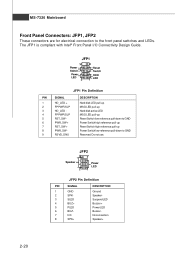
... Power Switch high reference pull-up Reset Switch high reference pull-up Power Switch low reference pull-down to the front panel switches and LEDs. MS-7320 Mainboard Front Panel Connectors: JFP1, JFP2 These connectors are for electrical connection to GND Reserved. The JFP1 is compliant with Intel® Front Panel I/O Connectivity...
... Power Switch high reference pull-up Reset Switch high reference pull-up Power Switch low reference pull-down to the front panel switches and LEDs. MS-7320 Mainboard Front Panel Connectors: JFP1, JFP2 These connectors are for electrical connection to GND Reserved. The JFP1 is compliant with Intel® Front Panel I/O Connectivity...
User Guide
Page 36
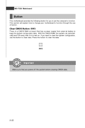
... is turned on board that you power off the system before clearing CMOS data. 2-22 This section will explain how to change your motherboard's function through the use the button to clear data. MS-7320 Mainboard Button This motherboard provides the following button for you want to clear the system configuration, use of button.
... is turned on board that you power off the system before clearing CMOS data. 2-22 This section will explain how to change your motherboard's function through the use the button to clear data. MS-7320 Mainboard Button This motherboard provides the following button for you want to clear the system configuration, use of button.
User Guide
Page 38
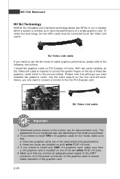
... graphics card is required to connect the golden fingers on the top of the graphics card. 2-24 The appearance of the same brand and specifications; MS-7320 Mainboard NV SLI Technology NVIDIA SLI (Scalable Link Interface) technology allows two GPUs to run in this technology, the two GPU cards must be connected...
... graphics card is required to connect the golden fingers on the top of the graphics card. 2-24 The appearance of the same brand and specifications; MS-7320 Mainboard NV SLI Technology NVIDIA SLI (Scalable Link Interface) technology allows two GPUs to run in this technology, the two GPU cards must be connected...
User Guide
Page 40
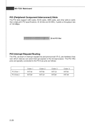
... 133 MBps. 32-bit PCI Slot PCI Interrupt Request Routing The IRQ, acronym of interrupt request line and pronounced I-R-Q, are typically connected to the microprocessor. MS-7320 Mainboard PCI (Peripheral Component Interconnect) Slots The PCI slots support LAN cards, SCSI cards, USB cards, and other add-on cards that comply with PCI...
... 133 MBps. 32-bit PCI Slot PCI Interrupt Request Routing The IRQ, acronym of interrupt request line and pronounced I-R-Q, are typically connected to the microprocessor. MS-7320 Mainboard PCI (Peripheral Component Interconnect) Slots The PCI slots support LAN cards, SCSI cards, USB cards, and other add-on cards that comply with PCI...
User Guide
Page 42
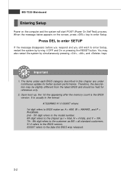
You may be slightly different from the latest BIOS and should be held for better system performance. MS-7320 Mainboard Entering Setup Power on the screen, press key to enter Setup. The items under each BIOS category described in the format: A7320NMS V1.0 033007 ... the system by turning it OFF and On or pressing the RESET button. V1.0 refers to the BIOS version. 033007 refers to the customer as MS = all standard customers. Press DEL to enter SETUP If the message disappears before you respond and you still wish to enter Setup, restart the system...
You may be slightly different from the latest BIOS and should be held for better system performance. MS-7320 Mainboard Entering Setup Power on the screen, press key to enter Setup. The items under each BIOS category described in the format: A7320NMS V1.0 033007 ... the system by turning it OFF and On or pressing the RESET button. V1.0 refers to the BIOS version. 033007 refers to the customer as MS = all standard customers. Press DEL to enter SETUP If the message disappears before you respond and you still wish to enter Setup, restart the system...
User Guide
Page 44
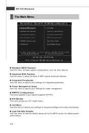
... Setup Use this menu to setup the items of AMI® special enhanced features. PNP/PCI Configurations This entry appears if your PC health status. MS-7320 Mainboard The Main Menu Standard CMOS Features Use this menu for power management. H/W Monitor This entry shows your system supports PnP/PCI. Integrated Peripherals Use...
... Setup Use this menu to setup the items of AMI® special enhanced features. PNP/PCI Configurations This entry appears if your PC health status. MS-7320 Mainboard The Main Menu Standard CMOS Features Use this menu for power management. H/W Monitor This entry shows your system supports PnP/PCI. Integrated Peripherals Use...
User Guide
Page 46
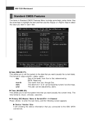
... be adjusted by BIOS. The time format is . Primary IDE Master/ Slave & Serial-ATA 1~6 Channel Press to 31 can be keyed by numeric function keys. MS-7320 Mainboard Standard CMOS Features The items in each item. Read-only. date The date from Jan. Date (MM:DD:YY) This allows you to set...
... be adjusted by BIOS. The time format is . Primary IDE Master/ Slave & Serial-ATA 1~6 Channel Press to 31 can be keyed by numeric function keys. MS-7320 Mainboard Standard CMOS Features The items in each item. Read-only. date The date from Jan. Date (MM:DD:YY) This allows you to set...
User Guide
Page 48
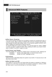
... on the numeric keypad. 3-8 Settings are: [Enabled] Shows a still image (logo) on . To successfully update the BIOS, you to update the BIOS with a Flash utility. MS-7320 Mainboard Advanced BIOS Features Boot Sector Protection This function protects the BIOS from accidental corruption by unauthorized users or computer viruses. After updating the BIOS...
... on the numeric keypad. 3-8 Settings are: [Enabled] Shows a still image (logo) on . To successfully update the BIOS, you to update the BIOS with a Flash utility. MS-7320 Mainboard Advanced BIOS Features Boot Sector Protection This function protects the BIOS from accidental corruption by unauthorized users or computer viruses. After updating the BIOS...
User Guide
Page 50
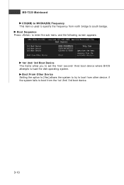
Boot Sequence Press to enter the sub-menu and the following screen appears: 1st/ 2nd/ 3rd Boot Device The items allow you to set the first/ second/ third boot device where BIOS attempts to south beidge. if the system fails to boot from the 1st/ 2nd/ 3rd boot device. 3-10 Boot From Other Device Setting the option to [Yes] allows the system to try to boot from other device. MS-7320 Mainboard C55(NB) to NVIDIA(SB) Frequency This item is used to specify the frequency from north bridge to load the disk operating system.
Boot Sequence Press to enter the sub-menu and the following screen appears: 1st/ 2nd/ 3rd Boot Device The items allow you to set the first/ second/ third boot device where BIOS attempts to south beidge. if the system fails to boot from the 1st/ 2nd/ 3rd boot device. 3-10 Boot From Other Device Setting the option to [Yes] allows the system to try to boot from other device. MS-7320 Mainboard C55(NB) to NVIDIA(SB) Frequency This item is used to specify the frequency from north bridge to load the disk operating system.
User Guide
Page 52
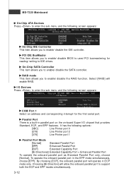
... parallel port will enable RAID. It has the following screen appears: COM Port 1 Select an address and corresponding interrupt for reading/ writing to IDE drives. MS-7320 Mainboard On-Chip ATA Devices Press to enter the sub-menu and the following screen appears: On-Chip IDE Controller This item allows you to...
... parallel port will enable RAID. It has the following screen appears: COM Port 1 Select an address and corresponding interrupt for reading/ writing to IDE drives. MS-7320 Mainboard On-Chip ATA Devices Press to enter the sub-menu and the following screen appears: On-Chip IDE Controller This item allows you to...


