User Guide
Page 8
... Interference Statement iv W EEE (Waste Electrical and Electronic Equipment) Statement v Chapter 1 Getting Started 1-1 Mainboard Specifications 1-2 Mainboard Layout 1-4 Packing Checklist 1-5 Chapter 2 Hardware Setup 2-1 Quick Components Guide 2-2 CPU (Central Processing Unit 2-3 Memory ...2-7 Power Supply ...2-9 Back Panel ...2-11 Connectors ...2-13 Button ...2-22 Slots ...2-23 Chapter 3 BIOS Setup 3-1 Entering Setup ...3-2 The Main Menu ...3-4 Standard CMOS...
... Interference Statement iv W EEE (Waste Electrical and Electronic Equipment) Statement v Chapter 1 Getting Started 1-1 Mainboard Specifications 1-2 Mainboard Layout 1-4 Packing Checklist 1-5 Chapter 2 Hardware Setup 2-1 Quick Components Guide 2-2 CPU (Central Processing Unit 2-3 Memory ...2-7 Power Supply ...2-9 Back Panel ...2-11 Connectors ...2-13 Button ...2-22 Slots ...2-23 Chapter 3 BIOS Setup 3-1 Entering Setup ...3-2 The Main Menu ...3-4 Standard CMOS...
User Guide
Page 11
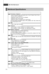
... 300 MB/s - 1 external-SATA port by Sil4723 - SATA6~7 support RAID 0 or RAID 1 mode - Supports Hyper-Threading (HT) Technology (For the latest information about CPU, please visit http://www.msi. Supports transfer rate up to 7.1 CH EAX 5.0 Surround Sound - Transfer rate is up to 400Mbps Creative SB X-Fi Xtreme H/W Audio - 24-bit / 96KHz...
... 300 MB/s - 1 external-SATA port by Sil4723 - SATA6~7 support RAID 0 or RAID 1 mode - Supports Hyper-Threading (HT) Technology (For the latest information about CPU, please visit http://www.msi. Supports transfer rate up to 7.1 CH EAX 5.0 Surround Sound - Transfer rate is up to 400Mbps Creative SB X-Fi Xtreme H/W Audio - 24-bit / 96KHz...
User Guide
Page 17
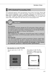
...or beyond product specifications is the Pin 1 indicator 2-3 For the latest information about CPU, please visit http://www.msi.com.tw/cpusupport.htm Important Overheating Overheating will seriously damage the CPU and system. Make sure that you are able to enhance heat dissipation. Any attempt ...triangle is not recommended. Always make sure to install the cooler to LGA 775 CPU The pin-pad side of LGA 775 CPU. Replaceing the CPU While replacing the CPU, always turn off the ATX power supply or unplug the power supply's power cord from overheating. Overclocking This...
...or beyond product specifications is the Pin 1 indicator 2-3 For the latest information about CPU, please visit http://www.msi.com.tw/cpusupport.htm Important Overheating Overheating will seriously damage the CPU and system. Make sure that you are able to enhance heat dissipation. Any attempt ...triangle is not recommended. Always make sure to install the cooler to LGA 775 CPU The pin-pad side of LGA 775 CPU. Replaceing the CPU While replacing the CPU, always turn off the ATX power supply or unplug the power supply's power cord from overheating. Overclocking This...
User Guide
Page 18
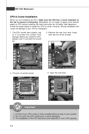
...Before you are installing the CPU, make sure the CPU has a cooler attached on your CPU cooler is firmly installed before installing the heat sink/cooler fan for better heat dispersion. The pins of your CPU packing. 2-4 Do not touch the CPU socket pins to install the CPU & cooler correctly. Remove the... cap from damage. Meanwhile, do not forget to apply some thermal paste on CPU before turning on the top to prevent overheating. ...
...Before you are installing the CPU, make sure the CPU has a cooler attached on your CPU cooler is firmly installed before installing the heat sink/cooler fan for better heat dispersion. The pins of your CPU packing. 2-4 Do not touch the CPU socket pins to install the CPU & cooler correctly. Remove the... cap from damage. Meanwhile, do not forget to apply some thermal paste on CPU before turning on the top to prevent overheating. ...
User Guide
Page 19
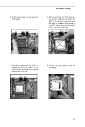
Lift the load lever up and open the load plate. Note that the alignment keys are matched. Visually inspect if the CPU is seated well into the socket. Be sure to grasp on the edge of the CPU base. Hardware Setup 6. Cover the load plate onto the p ac k age. 2-5 alignment key 7. If not, take out the CPU with pure vertical motion and reinstall. 8. After confirming the CPU direction for correct mating, put down the CPU in the socket housing frame. 5.
Lift the load lever up and open the load plate. Note that the alignment keys are matched. Visually inspect if the CPU is seated well into the socket. Be sure to grasp on the edge of the CPU base. Hardware Setup 6. Cover the load plate onto the p ac k age. 2-5 alignment key 7. If not, take out the CPU with pure vertical motion and reinstall. 8. After confirming the CPU direction for correct mating, put down the CPU in the socket housing frame. 5.
User Guide
Page 20
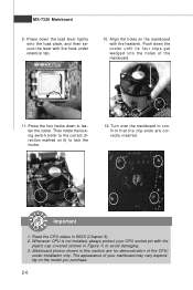
...h ook s . 12. Then rotate the locking switch (refer to avoid damaging. 3. Whenever CPU is not installed, always protect your mainboard may vary depending on the model you purchase. 2-6 Read the CPU status in Figure 1) to the correct direction marked on the mainboard with the heatsink. Press the... four hooks down the cooler until its four clips get wedged into the holes of the CPU/ cooler installation only. locking switch Important 1. Mainboard photos shown in this section are correctly inserted. Turn over the mainboard to fasten ...
...h ook s . 12. Then rotate the locking switch (refer to avoid damaging. 3. Whenever CPU is not installed, always protect your mainboard may vary depending on the model you purchase. 2-6 Read the CPU status in Figure 1) to the correct direction marked on the mainboard with the heatsink. Press the... four hooks down the cooler until its four clips get wedged into the holes of the CPU/ cooler installation only. locking switch Important 1. Mainboard photos shown in this section are correctly inserted. Turn over the mainboard to fasten ...

User Guide
Page 23
... the plug of 450 watts (and above) is inserted in the proper orientation and the pins are connected to proper ATX power supplies to ensure stable operation of the mainboard. 2. JPW1 4 8 1 5 Pin Definition PIN SIGNAL PIN SIGNAL... GND pin 13 pin 12 ATX 12V Power Connector: JPW1 This power connector is also a foolproof design on pin 11, 12, 23 & 24 to the CPU. Make sure that all the... connectors are aligned. There is used to provide power to avoid wrong installation. You may use the 20-pin ATX power supply, please plug...
... the plug of 450 watts (and above) is inserted in the proper orientation and the pins are connected to proper ATX power supplies to ensure stable operation of the mainboard. 2. JPW1 4 8 1 5 Pin Definition PIN SIGNAL PIN SIGNAL... GND pin 13 pin 12 ATX 12V Power Connector: JPW1 This power connector is also a foolproof design on pin 11, 12, 23 & 24 to the CPU. Make sure that all the... connectors are aligned. There is used to provide power to avoid wrong installation. You may use the 20-pin ATX power supply, please plug...

User Guide
Page 30
...record this status and show a warning message on -board, you must use a specially designed fan with 3 or 4 pins are both available for proper CPU cooling fan. 2. The system will be activated. GND +12V SENSOR Control GND +12V NC CPUFAN1 Sensor +12V GND NBFAN1 GND +12V NC SYSFAN1 ... has a System Hardware Monitor chipset on the screen. W hen connecting the wire to the connectors, always note that will automatically control the CPU fan speed according to the chassis intrusion switch cable. the black wire is the positive and should be connected to GND. MS-7320 Mainboard Fan...
...record this status and show a warning message on -board, you must use a specially designed fan with 3 or 4 pins are both available for proper CPU cooling fan. 2. The system will be activated. GND +12V SENSOR Control GND +12V NC CPUFAN1 Sensor +12V GND NBFAN1 GND +12V NC SYSFAN1 ... has a System Hardware Monitor chipset on the screen. W hen connecting the wire to the connectors, always note that will automatically control the CPU fan speed according to the chassis intrusion switch cable. the black wire is the positive and should be connected to GND. MS-7320 Mainboard Fan...
User Guide
Page 35
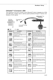
... the D-Bracket™2 which integrates four LEDs and USB ports. Then, detect and initializethe video adapter. 1 2 EarlyChipset Initialization 3 4 BIOS Sign On 1 2 This will start detecting CPU clock, 4 checking type ofvideo onboard. properly. 1 2 Decompressing BIOS image to RAM 1 2 Assign Resources to all ISA. 3 4 for you to connect to 3 D-LED will hang if...
... the D-Bracket™2 which integrates four LEDs and USB ports. Then, detect and initializethe video adapter. 1 2 EarlyChipset Initialization 3 4 BIOS Sign On 1 2 This will start detecting CPU clock, 4 checking type ofvideo onboard. properly. 1 2 Decompressing BIOS image to RAM 1 2 Assign Resources to all ISA. 3 4 for you to connect to 3 D-LED will hang if...
User Guide
Page 47
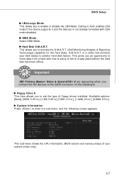
.... Important IDE Primary M aster/ Slave & Serial-ATA1~6 are appearing when you connect the HD devices to predict hard disk failure. This sub-menu shows the CPU information, BIOS version and memory status of floppy drives installed. Hard Disk S.M.A.R.T. This gives you an opportunity to move data from a hard disk that monitors...
.... Important IDE Primary M aster/ Slave & Serial-ATA1~6 are appearing when you connect the HD devices to predict hard disk failure. This sub-menu shows the CPU information, BIOS version and memory status of floppy drives installed. Hard Disk S.M.A.R.T. This gives you an opportunity to move data from a hard disk that monitors...
User Guide
Page 49
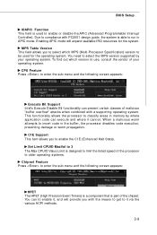
... mode. C1E Support This item allows you with a supporting operating system. Enabling APIC mode will provide you to enable it via the various ACPI methods. 3-9 CPU Feature Press to insert code in the buffer, the processor disables code execution, preventing damage or worm propagation. W hen a malicious worm attempts to enter the...
... mode. C1E Support This item allows you with a supporting operating system. Enabling APIC mode will provide you to enable it via the various ACPI methods. 3-9 CPU Feature Press to insert code in the buffer, the processor disables code execution, preventing damage or worm propagation. W hen a malicious worm attempts to enter the...
User Guide
Page 53
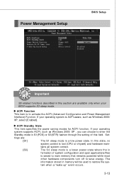
... system when a "wake up" event occurs. 3-13 Power Management Setup BIOS Setup Important S3-related functions described in this state, no system context is lost (CPU or chipset) and hardware main- tains all system context. [S3] The S3 sleep mode is a lower power state where the in S1(POS) or S3...
... system when a "wake up" event occurs. 3-13 Power Management Setup BIOS Setup Important S3-related functions described in this state, no system context is lost (CPU or chipset) and hardware main- tains all system context. [S3] The S3 sleep mode is a lower power state where the in S1(POS) or S3...
User Guide
Page 56
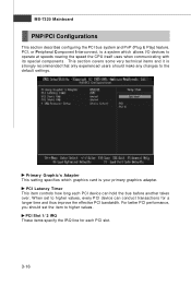
... section covers some very technical items and it is strongly recommended that only experienced users should set to operate at speeds nearing the speed the CPU itself uses when communicating with its special components. Primary Graphic's Adapter This setting specifies which graphics card is a system which allows I/O devices to higher values...
... section covers some very technical items and it is strongly recommended that only experienced users should set to operate at speeds nearing the speed the CPU itself uses when communicating with its special components. Primary Graphic's Adapter This setting specifies which graphics card is a system which allows I/O devices to higher values...
User Guide
Page 58
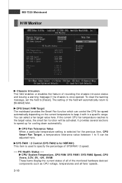
.../ 2 Control (SYS FAN2 is for NBFAN1) This item is selected for cooling down automaticlly. PC Health Status ---- CPU/ System Temperature, CPU FAN/ SYS FAN1/ SYS FAN2 Speed, CPU Vcore, 3.3V, 5V, 12V, 5VSB These items display the current status of all of recording the chassis intrusion status ... Monitor Chassis Intrusion The field enables or disables the feature of the monitored hardware devices/ components such as CPU voltage, temperatures and all fans' speeds. 3-18 If the current CPU fan temperature reaches to the target value, the smart fan function will automatically return to 5 can be ...
.../ 2 Control (SYS FAN2 is for NBFAN1) This item is selected for cooling down automaticlly. PC Health Status ---- CPU/ System Temperature, CPU FAN/ SYS FAN1/ SYS FAN2 Speed, CPU Vcore, 3.3V, 5V, 12V, 5VSB These items display the current status of all of recording the chassis intrusion status ... Monitor Chassis Intrusion The field enables or disables the feature of the monitored hardware devices/ components such as CPU voltage, temperatures and all fans' speeds. 3-18 If the current CPU fan temperature reaches to the target value, the smart fan function will automatically return to 5 can be ...
User Guide
Page 59
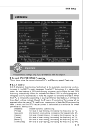
... overclocking, increasing the frequency by 7%. [General] 5th level of overclocking, increasing the frequency by 10%. [Commander] 6th level of CPU while running programs, it will speed up to make the program run smoothly and faster. Settings are familiar with the chipset. Read-... only when users' PC need to adjust the best CPU frequency automatically. D.O.T Control D.O.T. (Dynamic Overclocking Technology) is running programs, and to run huge amount of CPU and Memory speed. W hen the motherboard detects CPU is the automatic overclocking function, included in the low load...
... overclocking, increasing the frequency by 7%. [General] 5th level of overclocking, increasing the frequency by 10%. [Commander] 6th level of CPU while running programs, it will speed up to make the program run smoothly and faster. Settings are familiar with the chipset. Read-... only when users' PC need to adjust the best CPU frequency automatically. D.O.T Control D.O.T. (Dynamic Overclocking Technology) is running programs, and to run huge amount of CPU and Memory speed. W hen the motherboard detects CPU is the automatic overclocking function, included in the low load...
User Guide
Page 60
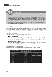
... allows you find the PC appears to be unstable or reboot incidentally, it is still risky. We suggest user to make sure that your CPU can afford to select the memory clock frequency (in MHz). MS-7320 Mainboard Important Even though the Dynamic Overclocking Technology is more stable than ...menu and the following two items. FSB Clock (MHz) W hen the System Clock Mode sets to select the CPU Front Side Bus clock frequency (in MHz). This item allows you installed the CPU which support speedstep technology. System Clock Mode This item is used to switch the following screen appears. 3-20
... allows you find the PC appears to be unstable or reboot incidentally, it is still risky. We suggest user to make sure that your CPU can afford to select the memory clock frequency (in MHz). MS-7320 Mainboard Important Even though the Dynamic Overclocking Technology is more stable than ...menu and the following two items. FSB Clock (MHz) W hen the System Clock Mode sets to select the CPU Front Side Bus clock frequency (in MHz). This item allows you installed the CPU which support speedstep technology. System Clock Mode This item is used to switch the following screen appears. 3-20
User Guide
Page 62
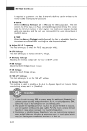
...not have any EMI problem, leave the setting at [Disabled] for EMI reduction. 2. FSB VTT Voltage This item allows you to increase the CPU voltage. Remember to disable Spread Spectrum if you are overclocking because even a slight jitter can introduce a temporary boost in clock speed which may just... cause your local EMI regulation. 3. CPU Voltage This item allows you to set to enable or disable the Spread Spectrum feature. Spread Spectrum This setting is used to [Manual], the ...
...not have any EMI problem, leave the setting at [Disabled] for EMI reduction. 2. FSB VTT Voltage This item allows you to increase the CPU voltage. Remember to disable Spread Spectrum if you are overclocking because even a slight jitter can introduce a temporary boost in clock speed which may just... cause your local EMI regulation. 3. CPU Voltage This item allows you to set to enable or disable the Spread Spectrum feature. Spread Spectrum This setting is used to [Manual], the ...
User Guide
Page 110
... CoreCenter, please make sure the system has meet the following requirements: 1. DotNet Frame Work 2.0 D-1 Intel Pentium4 / Celeron, AMD Athlon XP/ Sempron or compatible CPU with PCI Express slot. 2. 256MB system memory. 3. Operation system: W indows XP. 5. CD-ROM drive for software installation. 4. Dual Core Center Appendix D... Dual Core Center Dual CoreCenter, the most useful and powerful utility that MSI has spent much research and efforts to develop, helps users to monitor or configure the hardware status of...
... CoreCenter, please make sure the system has meet the following requirements: 1. DotNet Frame Work 2.0 D-1 Intel Pentium4 / Celeron, AMD Athlon XP/ Sempron or compatible CPU with PCI Express slot. 2. 256MB system memory. 3. Operation system: W indows XP. 5. CD-ROM drive for software installation. 4. Dual Core Center Appendix D... Dual Core Center Dual CoreCenter, the most useful and powerful utility that MSI has spent much research and efforts to develop, helps users to monitor or configure the hardware status of...
User Guide
Page 112
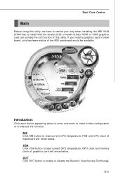
... hardware status of mainboard will show below . VGA Click VGA button to enable or disable the Dynamic Overclocking Technology. If you : only when installing the MSI V044 (V044 has to execute the function. Dual Core Center Main Before using this utility. DOT Click DOT button to read current...
... hardware status of mainboard will show below . VGA Click VGA button to enable or disable the Dynamic Overclocking Technology. If you : only when installing the MSI V044 (V044 has to execute the function. Dual Core Center Main Before using this utility. DOT Click DOT button to read current...
User Guide
Page 114
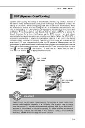
... enhance the overall performance. W hen the graphics card detects that the loading of data, like 3D games or video process, and the motherboard/ graphicd card need to conduct overclocking manually, please do not to apply the DOT function. DOT FSB-UP Rate button DOT FSB-DOWN...stable than manual overclocking, basically, it is temporarily suspending or staying in the MSITM's newly developed Dual CoreCenter Technology. When the motherboard detects that your CPU can afford to overclock regularly first. By the way, if you have to click the DOT button to apply the DOT function....
... enhance the overall performance. W hen the graphics card detects that the loading of data, like 3D games or video process, and the motherboard/ graphicd card need to conduct overclocking manually, please do not to apply the DOT function. DOT FSB-UP Rate button DOT FSB-DOWN...stable than manual overclocking, basically, it is temporarily suspending or staying in the MSITM's newly developed Dual CoreCenter Technology. When the motherboard detects that your CPU can afford to overclock regularly first. By the way, if you have to click the DOT button to apply the DOT function....

