User Guide
Page 8
... Connectors 2-12 Jumpers 2-20 Button 2-21 Slots 2-22 LED Status Indicators 2-28 Chapter 3 BIOS Setup 3-1 Entering Setup 3-2 The Main Menu 3-4 Standard CMOS Features 3-6 Advanced BIOS Features 3-8 Integrated Peripherals 3-10 Power Management Setup 3-12 H/W Monitor 3-15 Green Power 3-16 BIOS Setting Password 3-17 Cell Menu 3-19 M-Flash 3-27 Overclocking Profile 3-30 Load Fail-Safe/ Optimized...
... Connectors 2-12 Jumpers 2-20 Button 2-21 Slots 2-22 LED Status Indicators 2-28 Chapter 3 BIOS Setup 3-1 Entering Setup 3-2 The Main Menu 3-4 Standard CMOS Features 3-6 Advanced BIOS Features 3-8 Integrated Peripherals 3-10 Power Management Setup 3-12 H/W Monitor 3-15 Green Power 3-16 BIOS Setting Password 3-17 Cell Menu 3-19 M-Flash 3-27 Overclocking Profile 3-30 Load Fail-Safe/ Optimized...

User Guide
Page 9
... Realtek HD Audio Driver A-2 Software Configuration A-4 Hardware Setup A-19 Appendix B Control Center B-1 Activating Control Center B-2 System Information B-3 Overclocking B-5 Green Power B-7 Appendix C Intel SATA RAID C-1 Introduction C-2 BIOS Configuration C-3 Installing Driver C-10 Installing Software C-12 RAID Migration Instructions C-16 Recovery Volume Creation C-23 Degraded RAID Array C-26 Appendix D JMicron RAID Introduction D-1 Introduction D-2 JMicron...
... Realtek HD Audio Driver A-2 Software Configuration A-4 Hardware Setup A-19 Appendix B Control Center B-1 Activating Control Center B-2 System Information B-3 Overclocking B-5 Green Power B-7 Appendix C Intel SATA RAID C-1 Introduction C-2 BIOS Configuration C-3 Installing Driver C-10 Installing Software C-12 RAID Migration Instructions C-16 Recovery Volume Creation C-23 Degraded RAID Array C-26 Appendix D JMicron RAID Introduction D-1 Introduction D-2 JMicron...

User Guide
Page 38
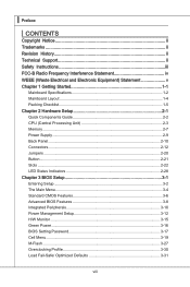
PCI Express x16 Slot PCI Express x4 Slot PCI Express x1 Slot Important When adding or removing expansion cards, make sure that you unplug the power supply first. Meanwhile, read the documentation for the expansion card to configure any necessary hardware or software settings for the expansion card, such as jumpers, switches or BIOS configuration. 2-22 ▍ Hardware Setup Slots PCIE (Peripheral Component Interconnect Express) Slot The PCI Express slot supports the PCI Express interface expansion card.
PCI Express x16 Slot PCI Express x4 Slot PCI Express x1 Slot Important When adding or removing expansion cards, make sure that you unplug the power supply first. Meanwhile, read the documentation for the expansion card to configure any necessary hardware or software settings for the expansion card, such as jumpers, switches or BIOS configuration. 2-22 ▍ Hardware Setup Slots PCIE (Peripheral Component Interconnect Express) Slot The PCI Express slot supports the PCI Express interface expansion card.
User Guide
Page 43
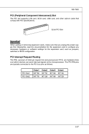
... The IRQ, acronym of interrupt request line and pronounced I-R-Q, are typically connected to the PCI bus pins as jumpers, switches or BIOS configuration. Meanwhile, read the documentation for the expansion card to the microprocessor. The PCI IRQ pins are hardware lines over which devices... can send interrupt signals to configure any necessary hardware or software settings for the expansion card, such as follows: PCI Slot1 PCI Slot2 Order1 INT E# INT F# Order2 INT F# INT G# Order3 INT G# INT H# ...
... The IRQ, acronym of interrupt request line and pronounced I-R-Q, are typically connected to the PCI bus pins as jumpers, switches or BIOS configuration. Meanwhile, read the documentation for the expansion card to the microprocessor. The PCI IRQ pins are hardware lines over which devices... can send interrupt signals to configure any necessary hardware or software settings for the expansion card, such as follows: PCI Slot1 PCI Slot2 Order1 INT E# INT F# Order2 INT F# INT G# Order3 INT G# INT H# ...

User Guide
Page 45
You may need to run SETUP. ■ You want to configure the system for customized features. 2-3-1 Chapter 3 BIOS Setup This chapter provides information on the screen during the system booting up, and requests you to run the Setup program when: ■ An error message appears on the BIOS Setup program and allows you to change the default settings for optimum use.
You may need to run SETUP. ■ You want to configure the system for customized features. 2-3-1 Chapter 3 BIOS Setup This chapter provides information on the screen during the system booting up, and requests you to run the Setup program when: ■ An error message appears on the BIOS Setup program and allows you to change the default settings for optimum use.

User Guide
Page 48
...for basic system configurations, such as time, date etc. ▶ Advanced BIOS Features Use this menu to setup the items of the BIOS special enhanced features. ▶ Integrated Peripherals Use this menu to specify your settings for integrated peripherals. ▶ Power Management Setup Use this menu to ...specify your settings for power management. ▶ H/W Monitor This entry shows your PC health status. ▶ Green Power Use this menu to specify the power phase. ▶ BIOS Setting Password Use this menu to set the password for BIOS. ▶ Cell Menu Use this menu...
...for basic system configurations, such as time, date etc. ▶ Advanced BIOS Features Use this menu to setup the items of the BIOS special enhanced features. ▶ Integrated Peripherals Use this menu to specify your settings for integrated peripherals. ▶ Power Management Setup Use this menu to ...specify your settings for power management. ▶ H/W Monitor This entry shows your PC health status. ▶ Green Power Use this menu to specify the power phase. ▶ BIOS Setting Password Use this menu to set the password for BIOS. ▶ Cell Menu Use this menu...

User Guide
Page 49
... FAT32 format only). ▶ Overclocking Profile Use this menu to save/ load your settings to/ from CMOS for BIOS. ▶ Load Fail-Safe Defaults Use this menu to load the default values set by the BIOS vendor for stable system performance. ▶ Load Optimized Defaults Use this menu to load ...the default values set by the mainboard manufacturer specifically for optimal performance of the mainboard. ▶ Save & Exit ...
... FAT32 format only). ▶ Overclocking Profile Use this menu to save/ load your settings to/ from CMOS for BIOS. ▶ Load Fail-Safe Defaults Use this menu to load the default values set by the BIOS vendor for stable system performance. ▶ Load Optimized Defaults Use this menu to load ...the default values set by the mainboard manufacturer specifically for optimal performance of the mainboard. ▶ Save & Exit ...

User Guide
Page 50
...Sat, determined by users. ▶ Time (HH:MM:SS) This allows you to set the system to the date that you want (usually the current time). Read- only.... by numeric function keys. [year] The year can be adjusted by BIOS. ▍ BIOS Setup Standard CMOS Features The items in Standard CMOS Features Menu include some... basic setup items. Use the arrow keys to highlight the item and then use the or keys to select the value you want in each item. ▶ Date (MM:DD:YY) This allows you to set...
...Sat, determined by users. ▶ Time (HH:MM:SS) This allows you to set the system to the date that you want (usually the current time). Read- only.... by numeric function keys. [year] The year can be adjusted by BIOS. ▍ BIOS Setup Standard CMOS Features The items in Standard CMOS Features Menu include some... basic setup items. Use the arrow keys to highlight the item and then use the or keys to select the value you want in each item. ▶ Date (MM:DD:YY) This allows you to set...

User Guide
Page 51
... sub-menu, and the following screen appears: ▶ Device / Vendor / Size It will show the device information that you to set the type of floppy drives installed. ▶ Hold on The setting determines whether the system will stop for 15 seconds and then automatically resume its operation. This sub-menu shows the...
... sub-menu, and the following screen appears: ▶ Device / Vendor / Size It will show the device information that you to set the type of floppy drives installed. ▶ Hold on The setting determines whether the system will stop for 15 seconds and then automatically resume its operation. This sub-menu shows the...
User Guide
Page 52
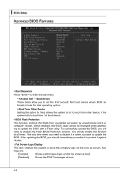
... to boot from 1st boot device. ▶ BIOS Flash Protection This function protects the BIOS from other device, if the system fails to update the BIOS with a Flash utility. The only time when you to set the first/ second/ third boot device where BIOS attempts to load the disk operating system. ▶...; Boot From Other Device Setting the option to [Yes] allows the system to try ...
... to boot from 1st boot device. ▶ BIOS Flash Protection This function protects the BIOS from other device, if the system fails to update the BIOS with a Flash utility. The only time when you to set the first/ second/ third boot device where BIOS attempts to load the disk operating system. ▶...; Boot From Other Device Setting the option to [Yes] allows the system to try ...

User Guide
Page 54
▍ BIOS Setup Integrated Peripherals ▶ USB Controller This setting allows you to enable/disable the onboard USB controller. ▶ USB Device Legacy Support Select [Enabled] if you need to use a USB-interfaced device in the operating system. ▶ Onboard LAN Controller This setting allows you to enable/disable... This item is used to decide whether to invoke the Boot ROM of the onboard LAN. ▶ Onboard 2nd LAN Controller This setting allows you to enable/disable the onboard 2nd LAN controller. ▶ Onboard IEEE1394 Controller (optional) This item allows you to enable/disable...
▍ BIOS Setup Integrated Peripherals ▶ USB Controller This setting allows you to enable/disable the onboard USB controller. ▶ USB Device Legacy Support Select [Enabled] if you need to use a USB-interfaced device in the operating system. ▶ Onboard LAN Controller This setting allows you to enable/disable... This item is used to decide whether to invoke the Boot ROM of the onboard LAN. ▶ Onboard 2nd LAN Controller This setting allows you to enable/disable the onboard 2nd LAN controller. ▶ Onboard IEEE1394 Controller (optional) This item allows you to enable/disable...

User Guide
Page 56
... only when the BIOS supports S3 sleep mode. ▶ ACPI Function This item is to enter the Standby mode in S1(POS) or S3(STR) fashion through the setting of system configuration and open applications/files is lost (CPU or chipset) and hardware maintains all sys- The information ...main memory that remains powered while most other hardware components turn off to restore the system when a "wake up" event occurs. 3-12 ▍ BIOS Setup Power Management Setup Important S3-related functions described in this section are : [S1] The S1 sleep mode is ACPI-aware, such as Windows...
... only when the BIOS supports S3 sleep mode. ▶ ACPI Function This item is to enter the Standby mode in S1(POS) or S3(STR) fashion through the setting of system configuration and open applications/files is lost (CPU or chipset) and hardware maintains all sys- The information ...main memory that remains powered while most other hardware components turn off to restore the system when a "wake up" event occurs. 3-12 ▍ BIOS Setup Power Management Setup Important S3-related functions described in this section are : [S1] The S1 sleep mode is ACPI-aware, such as Windows...
User Guide
Page 57
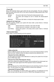
... ▶ Wake Up Event Setup Press and the following sub-menu appears. ▶ Wake up Event By Setting to [BIOS] activates the following fields, and use the following fields to set to [Enabled], the feature allows your system will available. MS-7583 ▶ Power LED When ACPI Standby State... is set to indicate the sleep/suspend state. Setting to [OS], the wake up events will be defined by OS....
... ▶ Wake Up Event Setup Press and the following sub-menu appears. ▶ Wake up Event By Setting to [BIOS] activates the following fields, and use the following fields to set to [Enabled], the feature allows your system will available. MS-7583 ▶ Power LED When ACPI Standby State... is set to indicate the sleep/suspend state. Setting to [OS], the wake up events will be defined by OS....

User Guide
Page 58
▍ BIOS Setup ▶ Resume By PCI-E Device When set to [Enabled], the feature allows your system to be awakened from the power saving modes through any event on PCIE device. ▶ Resume By Onboard LAN When set to [Enabled], the feature allows your system to be awakened from the power saving modes ...or disable the feature of booting up the system on a scheduled time/date. ▶ Date/Time (HH:MM:SS) If Resume By RTC Alarm is set to [Enabled], the system will automatically resume (boot up) on a specific date/hour/minute/second specified in these fields (using the and to select ...
▍ BIOS Setup ▶ Resume By PCI-E Device When set to [Enabled], the feature allows your system to be awakened from the power saving modes through any event on PCIE device. ▶ Resume By Onboard LAN When set to [Enabled], the feature allows your system to be awakened from the power saving modes ...or disable the feature of booting up the system on a scheduled time/date. ▶ Date/Time (HH:MM:SS) If Resume By RTC Alarm is set to [Enabled], the system will automatically resume (boot up) on a specific date/hour/minute/second specified in these fields (using the and to select ...

User Guide
Page 60
▍ BIOS Setup Green Power ▶ CPU Phase Control When set to [Auto], the hardware will auto adjust the CPU power phase according to the loading of CPU to reach the best power saving function. ▶ Mainboard LED Control This item is used to turn on (Auto)/ turn off (Disabled) the power phase LEDs of the mainboard. 3-16
▍ BIOS Setup Green Power ▶ CPU Phase Control When set to [Auto], the hardware will auto adjust the CPU power phase according to the loading of CPU to reach the best power saving function. ▶ Mainboard LED Control This item is used to turn on (Auto)/ turn off (Disabled) the power phase LEDs of the mainboard. 3-16
User Guide
Page 61
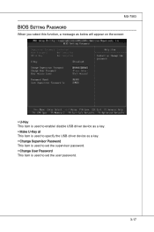
MS-7583 BIOS Setting Password When you select this function, a message as below will appear on the screen: ▶ U-Key This item is used to enable/ disable USB driver device as a key. ▶ Make U-Key at This item is used to specify the USB driver device as a key. ▶ Change Supervisor Password This item is used to set the supervisor password. ▶ Change User Password This item is used to set the user password. 3-17
MS-7583 BIOS Setting Password When you select this function, a message as below will appear on the screen: ▶ U-Key This item is used to enable/ disable USB driver device as a key. ▶ Make U-Key at This item is used to specify the USB driver device as a key. ▶ Change Supervisor Password This item is used to set the supervisor password. ▶ Change User Password This item is used to set the user password. 3-17

User Guide
Page 62
The password typed now will replace any previously set password, just press when you are described below: Option Description [BIOS] The password prompt appears only when end users try to run Setup. ▶ Save Supervisor Password to This item is used to limit the... prevents an unauthorized person from changing any part of the setup menu. About Supervisor Password & User Password: Supervisor password: Can enter and change the settings of BIOS password protection that is used to assign a place to save the supervisor password. 3-18 You will boot and you try to run Setup. [System...
The password typed now will replace any previously set password, just press when you are described below: Option Description [BIOS] The password prompt appears only when end users try to run Setup. ▶ Save Supervisor Password to This item is used to limit the... prevents an unauthorized person from changing any part of the setup menu. About Supervisor Password & User Password: Supervisor password: Can enter and change the settings of BIOS password protection that is used to assign a place to save the supervisor password. 3-18 You will boot and you try to run Setup. [System...

User Guide
Page 64
... following screen appears: ▶ Intel EIST The Enhanced Intel SpeedStep technology allows you installed the CPU which supports c-state technology. 3-20 ▍ BIOS Setup ▶ CPU Specifications Press to set the performance level of the microprocessor whether the computer is a power management state that significantly reduces the power of installed CPU. ▶...
... following screen appears: ▶ Intel EIST The Enhanced Intel SpeedStep technology allows you installed the CPU which supports c-state technology. 3-20 ▍ BIOS Setup ▶ CPU Specifications Press to set the performance level of the microprocessor whether the computer is a power management state that significantly reduces the power of installed CPU. ▶...

User Guide
Page 68
... PCI Frequency (MHz) This field allows you to select the PCI frequency (in MHz). ▶ Auto Disable DRAM/PCI Frequency When set the following advanced memory timings. ▶ Extreme Memory Profile (X.M.P.) This item is used to minimize the electromagnetic interference (EMI). 3-24 ... Read-only. ▶ QPI Ratio This item allows you to set the memory multiplier. ▶ Adjusted DRAM Frequency (MHz) It shows the adjusted DRAM frequency. ▍ BIOS Setup ▶ Channel 1/ Channel2 Advanced Memory Setting Setting to [Auto] enables the advance memory timing automatically to be determined...
... PCI Frequency (MHz) This field allows you to select the PCI frequency (in MHz). ▶ Auto Disable DRAM/PCI Frequency When set the following advanced memory timings. ▶ Extreme Memory Profile (X.M.P.) This item is used to minimize the electromagnetic interference (EMI). 3-24 ... Read-only. ▶ QPI Ratio This item allows you to set the memory multiplier. ▶ Adjusted DRAM Frequency (MHz) It shows the adjusted DRAM frequency. ▍ BIOS Setup ▶ Channel 1/ Channel2 Advanced Memory Setting Setting to [Auto] enables the advance memory timing automatically to be determined...

User Guide
Page 75
...Defaults, a message as below appears: Selecting Ok and pressing Enter loads the BIOS default values for optimal system performance. 3-31 The Fail-Safe Defaults are the default values set by the mainboard manufacturer specifically for stable system performance. When you select Load ... message as below appears: Selecting Ok and pressing Enter loads the default factory settings for the most stable, minimal system performance. The Optimized Defaults are the default values set by the BIOS vendor for optimal performance of the BIOS settings to restore all of the mainboard.
...Defaults, a message as below appears: Selecting Ok and pressing Enter loads the BIOS default values for optimal system performance. 3-31 The Fail-Safe Defaults are the default values set by the mainboard manufacturer specifically for stable system performance. When you select Load ... message as below appears: Selecting Ok and pressing Enter loads the default factory settings for the most stable, minimal system performance. The Optimized Defaults are the default values set by the BIOS vendor for optimal performance of the BIOS settings to restore all of the mainboard.

