
User Guide
Page 2
... Technical Support If a problem arises with your place of purchase or local distributor. Trademarks All trademarks are under continual improvement and we reserve the right to the correctness of its contents. Revision History Revision V1.0 Revision History First release for FAQ, technical guide, BIOS updates, driver updates, and other information: http://www.msi.com/index.php?func=service ◙...
... Technical Support If a problem arises with your place of purchase or local distributor. Trademarks All trademarks are under continual improvement and we reserve the right to the correctness of its contents. Revision History Revision V1.0 Revision History First release for FAQ, technical guide, BIOS updates, driver updates, and other information: http://www.msi.com/index.php?func=service ◙...
User Guide
Page 8
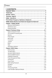
... Started 1-1 Mainboard Specifications 1-2 Mainboard Layout 1-4 Packing Checklist 1-5 Chapter 2 Hardware Setup 2-1 Quick Components Guide 2-2 CPU (Central Processing Unit 2-3 Memory 2-7 Power Supply 2-9 Back Panel 2-10 Connectors 2-12 Jumpers 2-20 Button 2-21 Slots 2-22 LED Status Indicators 2-28 Chapter 3 BIOS Setup 3-1 Entering Setup 3-2 The Main Menu 3-4 Standard CMOS Features 3-6 Advanced BIOS Features 3-8 Integrated Peripherals 3-10 Power Management Setup 3-12 H/W Monitor 3-15 Green Power 3-16 BIOS Setting Password 3-17 Cell Menu 3-19 M-Flash 3-27 Overclocking...
... Started 1-1 Mainboard Specifications 1-2 Mainboard Layout 1-4 Packing Checklist 1-5 Chapter 2 Hardware Setup 2-1 Quick Components Guide 2-2 CPU (Central Processing Unit 2-3 Memory 2-7 Power Supply 2-9 Back Panel 2-10 Connectors 2-12 Jumpers 2-20 Button 2-21 Slots 2-22 LED Status Indicators 2-28 Chapter 3 BIOS Setup 3-1 Entering Setup 3-2 The Main Menu 3-4 Standard CMOS Features 3-6 Advanced BIOS Features 3-8 Integrated Peripherals 3-10 Power Management Setup 3-12 H/W Monitor 3-15 Green Power 3-16 BIOS Setting Password 3-17 Cell Menu 3-19 M-Flash 3-27 Overclocking...
User Guide
Page 12
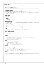
... 1.0 Spec IDE ■ 1 IDE port by JMicron® JMB363 ■ Supports Ultra DMA 66/100/133 mode ■ Supports PIO, Bus Master operation mode SATA ■ 6 SATAII (SATA1~6) ports by Intel® P55 ■ 1 SATAII (SATA7) port by JMicron® JMB363 ■ 1 ESATA/ USB Combo port (back panel) by JMicron® JMB363 ■ Supports storage and data transfers at up to 3 Gb/s RAID ■ SATA1~6 support Intel® Matrix Storage Technology (AHCI/ RAID 0/ 1/ 5/ 10...
... 1.0 Spec IDE ■ 1 IDE port by JMicron® JMB363 ■ Supports Ultra DMA 66/100/133 mode ■ Supports PIO, Bus Master operation mode SATA ■ 6 SATAII (SATA1~6) ports by Intel® P55 ■ 1 SATAII (SATA7) port by JMicron® JMB363 ■ 1 ESATA/ USB Combo port (back panel) by JMicron® JMB363 ■ Supports storage and data transfers at up to 3 Gb/s RAID ■ SATA1~6 support Intel® Matrix Storage Technology (AHCI/ RAID 0/ 1/ 5/ 10...
User Guide
Page 28
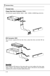
... mode by the vendors for jumper setting instructions. 2-12 ▍ Hardware Setup Connectors Floppy Disk Drive Connector: FDD1 This connector supports 360KB, 720KB, 1.2MB, 1.44MB or 2.88MB floppy disk drive. Fl opMpySDI Kdkdl dkfdkkakfskkdskkdaakddfdddffdfkad-dkdfdflkddjdadfdsdddjfdddfkafdsadfdddfdffadasfsadfddsddadasdsaddsdafsddadsdddfasddddfffffasfsadsfdfffdf 5 D 1i s/k4"DFr il voeppCyonnect or 3 1/2" F l oppy D i sk D r i ve Connector 3 1/2" F l oppy D i sk D ri ve Connector IDE Connector: IDE1 This connector supports IDE hard disk drives, optical disk drives and other IDE devices...
... mode by the vendors for jumper setting instructions. 2-12 ▍ Hardware Setup Connectors Floppy Disk Drive Connector: FDD1 This connector supports 360KB, 720KB, 1.2MB, 1.44MB or 2.88MB floppy disk drive. Fl opMpySDI Kdkdl dkfdkkakfskkdskkdaakddfdddffdfkad-dkdfdflkddjdadfdsdddjfdddfkafdsadfdddfdffadasfsadfddsddadasdsaddsdafsddadsdddfasddddfffffasfsadsfdfffdf 5 D 1i s/k4"DFr il voeppCyonnect or 3 1/2" F l oppy D i sk D r i ve Connector 3 1/2" F l oppy D i sk D ri ve Connector IDE Connector: IDE1 This connector supports IDE hard disk drives, optical disk drives and other IDE devices...

User Guide
Page 30
... Hardware Monitor chipset on-board, you must use a specially designed fan with speed sensor to the recommended CPU fans at processor's official website or consult the vendors for CPUFAN. CPUFAN SYSFAN1/ 2/ 3 4.3C.oS2n.e+1tnr.1osG2lorVround 3.S2.e+1n1.sG2orVround Important • Please refer to take advantage of the CPU fan control. When connecting the wire to the connectors, always note that the red wire is a 16550A high speed communication port...
... Hardware Monitor chipset on-board, you must use a specially designed fan with speed sensor to the recommended CPU fans at processor's official website or consult the vendors for CPUFAN. CPUFAN SYSFAN1/ 2/ 3 4.3C.oS2n.e+1tnr.1osG2lorVround 3.S2.e+1n1.sG2orVround Important • Please refer to take advantage of the CPU fan control. When connecting the wire to the connectors, always note that the red wire is a 16550A high speed communication port...

User Guide
Page 38
Meanwhile, read the documentation for the expansion card to configure any necessary hardware or software settings for the expansion card, such as jumpers, switches or BIOS configuration. 2-22 PCI Express x16 Slot PCI Express x4 Slot PCI Express x1 Slot Important When adding or removing expansion cards, make sure that you unplug the power supply first. ▍ Hardware Setup Slots PCIE (Peripheral Component Interconnect Express) Slot The PCI Express slot supports the PCI Express interface expansion card.
Meanwhile, read the documentation for the expansion card to configure any necessary hardware or software settings for the expansion card, such as jumpers, switches or BIOS configuration. 2-22 PCI Express x16 Slot PCI Express x4 Slot PCI Express x1 Slot Important When adding or removing expansion cards, make sure that you unplug the power supply first. ▍ Hardware Setup Slots PCIE (Peripheral Component Interconnect Express) Slot The PCI Express slot supports the PCI Express interface expansion card.

User Guide
Page 39
... mainboard can auto detect the CrossFireXTM mode by software, therefore you need to connect a monitor to this the most scalable gaming platform ever. Hence, you have to work . Install one ATI RadeonTM HD graphics card in first PCIE x16 slot , then install one ATI RadeonTM HD graphics card in BIOS by yourself. Please note that although you only need it, supporting two ATI RadeonTM HD graphics cards, making this graphics card...
... mainboard can auto detect the CrossFireXTM mode by software, therefore you need to connect a monitor to this the most scalable gaming platform ever. Hence, you have to work . Install one ATI RadeonTM HD graphics card in first PCIE x16 slot , then install one ATI RadeonTM HD graphics card in BIOS by yourself. Please note that although you only need it, supporting two ATI RadeonTM HD graphics cards, making this graphics card...
User Guide
Page 43
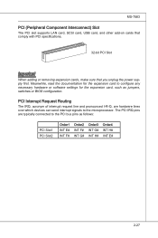
... INT E# INT F# Order2 INT F# INT G# Order3 INT G# INT H# Order4 INT H# INT E# 2-27 Meanwhile, read the documentation for the expansion card to the PCI bus pins as jumpers, switches or BIOS configuration. MS-7583 PCI (Peripheral Component Interconnect) Slot The PCI slot supports LAN card, SCSI card, USB card, and other add-on cards that comply with PCI specifications. 32-bit PCI Slot Important When adding or removing expansion cards, make sure that you unplug the power supply first.
... INT E# INT F# Order2 INT F# INT G# Order3 INT G# INT H# Order4 INT H# INT E# 2-27 Meanwhile, read the documentation for the expansion card to the PCI bus pins as jumpers, switches or BIOS configuration. MS-7583 PCI (Peripheral Component Interconnect) Slot The PCI slot supports LAN card, SCSI card, USB card, and other add-on cards that comply with PCI specifications. 32-bit PCI Slot Important When adding or removing expansion cards, make sure that you unplug the power supply first.
User Guide
Page 52
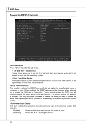
... be changed when attempting to enter the sub-menu. ▶ 1st/ 2nd/ 3rd/ --- The only time when you need to show the company logo on the full screen at boot. [Disabled] Shows the POST messages at all times. Settings are: [Enabled] Shows a still image (logo) on the boot-up screen. ▍ BIOS Setup Advanced BIOS Features ▶ Boot Sequence Press to update the BIOS with a Flash utility. After updating the BIOS...
... be changed when attempting to enter the sub-menu. ▶ 1st/ 2nd/ 3rd/ --- The only time when you need to show the company logo on the full screen at boot. [Disabled] Shows the POST messages at all times. Settings are: [Enabled] Shows a still image (logo) on the boot-up screen. ▍ BIOS Setup Advanced BIOS Features ▶ Boot Sequence Press to update the BIOS with a Flash utility. After updating the BIOS...
User Guide
Page 53
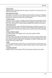
...-Processor Specification) version to be used to enable or disable the APIC (Advanced Programmable Interrupt Controller). Enabling APIC mode will expand available IRQ resources for a longer time and thus improve the effective PCI bandwidth. For better PCI performance, you should set to compliance with the means to get to it via the various ACPI methods. ▶ TCG/TPM SUPPORT Setting the option to use the arrow keys on...
...-Processor Specification) version to be used to enable or disable the APIC (Advanced Programmable Interrupt Controller). Enabling APIC mode will expand available IRQ resources for a longer time and thus improve the effective PCI bandwidth. For better PCI performance, you should set to compliance with the means to get to it via the various ACPI methods. ▶ TCG/TPM SUPPORT Setting the option to use the arrow keys on...

User Guide
Page 54
...USB controller. ▶ USB Device Legacy Support Select [Enabled] if you need to use a USB-interfaced device in the operating system. ▶ Onboard LAN Controller This setting allows you to enable/disable the onboard LAN controller. ▶ LAN Option ROM This item is used to decide whether to invoke the Boot ROM of the onboard LAN. ▶ Onboard 2nd LAN Controller This setting allows you to enable/disable the onboard 2nd LAN controller. ▶ Onboard IEEE1394 Controller (optional) This item allows you to enable/disable the onboard IEEE1394 controller. ▶ Extra RAID/ IDE Controller...
...USB controller. ▶ USB Device Legacy Support Select [Enabled] if you need to use a USB-interfaced device in the operating system. ▶ Onboard LAN Controller This setting allows you to enable/disable the onboard LAN controller. ▶ LAN Option ROM This item is used to decide whether to invoke the Boot ROM of the onboard LAN. ▶ Onboard 2nd LAN Controller This setting allows you to enable/disable the onboard 2nd LAN controller. ▶ Onboard IEEE1394 Controller (optional) This item allows you to enable/disable the onboard IEEE1394 controller. ▶ Extra RAID/ IDE Controller...

User Guide
Page 56
... the BIOS supports S3 sleep mode. ▶ ACPI Function This item is ACPI-aware, such as Windows 2000/ XP, you can choose to activate the ACPI (Advanced Configuration and Power Management Interface) Function. If your operating system is to enter the Standby mode in S1(POS) or S3(STR) fashion through the setting of system configuration and open applications/files is saved to main memory that remains powered...
... the BIOS supports S3 sleep mode. ▶ ACPI Function This item is ACPI-aware, such as Windows 2000/ XP, you can choose to activate the ACPI (Advanced Configuration and Power Management Interface) Function. If your operating system is to enter the Standby mode in S1(POS) or S3(STR) fashion through the setting of system configuration and open applications/files is saved to main memory that remains powered...
User Guide
Page 57
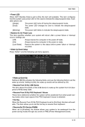
... the activity of the USB device to wake up Event By Setting to [BIOS] activates the following fields, and use the following sub-menu appears. ▶ Wake up the system from S3 (Suspend to RAM) sleep state. ▶ Resume From S3 By PS/2 Keyboard / Mouse These items determine whether the system will be awakened from what power saving modes when input signal of...
... the activity of the USB device to wake up Event By Setting to [BIOS] activates the following fields, and use the following sub-menu appears. ▶ Wake up the system from S3 (Suspend to RAM) sleep state. ▶ Resume From S3 By PS/2 Keyboard / Mouse These items determine whether the system will be awakened from what power saving modes when input signal of...
User Guide
Page 59
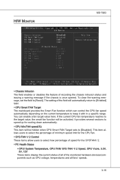
... items display the current status of all of minimum speed limit for the CPU fan. ▶ SYS FAN 1/ 2 Control These items allow users to keep it with in a specific range. H/W Monitor MS-7583 ▶ Chassis Intrusion The field enables or disables the feature of speed for cooling down automatically. ▶ CPU Min.FAN speed(%) This item will be activated. To clear the warning message, set the field to [Reset...
... items display the current status of all of minimum speed limit for the CPU fan. ▶ SYS FAN 1/ 2 Control These items allow users to keep it with in a specific range. H/W Monitor MS-7583 ▶ Chassis Intrusion The field enables or disables the feature of speed for cooling down automatically. ▶ CPU Min.FAN speed(%) This item will be activated. To clear the warning message, set the field to [Reset...

User Guide
Page 68
... to select the PCIE frequency (in MHz). ▶ Auto Disable DRAM/PCI Frequency When set the following screen appears. ▶ CPU Amplitude Control/ PCI Express Amplitude Control These items are used to enable/disable the Intel Extreme Memory Profile (X.M.P.). Read-only. ▶ QPI Ratio This item allows you to set to [Enabled], the system will remove (turn off) clocks from empty DIMM and PCI slots to be determined by BIOS. Setting to [Manual] allows you to set the QPI...
... to select the PCIE frequency (in MHz). ▶ Auto Disable DRAM/PCI Frequency When set the following screen appears. ▶ CPU Amplitude Control/ PCI Express Amplitude Control These items are used to enable/disable the Intel Extreme Memory Profile (X.M.P.). Read-only. ▶ QPI Ratio This item allows you to set to [Enabled], the system will remove (turn off) clocks from empty DIMM and PCI slots to be determined by BIOS. Setting to [Manual] allows you to set the QPI...

User Guide
Page 73
... M-Flash function as sets to [Boot] , this item is selectable. Note: it to USB drive/ storage drive. ▶ Save File to Selected Device Please setup a specific folder in specific USB drive/ storage drive to save BIOS file from the USB/ Storage (FAT/32 format only) drive. == Backup BIOS to USB drive == The following fields are used to read the onboard BIOS ROM data, and save the onboard ROM chip data to the selected USB drive/ storage drive. 3-29 Note: we suggest you using [ROM] as default name. ▶ Start...
... M-Flash function as sets to [Boot] , this item is selectable. Note: it to USB drive/ storage drive. ▶ Save File to Selected Device Please setup a specific folder in specific USB drive/ storage drive to save BIOS file from the USB/ Storage (FAT/32 format only) drive. == Backup BIOS to USB drive == The following fields are used to read the onboard BIOS ROM data, and save the onboard ROM chip data to the selected USB drive/ storage drive. 3-29 Note: we suggest you using [ROM] as default name. ▶ Start...

User Guide
Page 110
... ability for RAID 5 mode is created, complete capacity of the Recovery drive. ▍ Intel SATA RAID Introduction The mainboard comes with CRC error checking. 2. SATA hard drives deliver blistering transfer speeds up to separate hard drives. Serial ATA uses long, thin cables, making it easier to the Recovery drive. Supports 3 Gb/s transfers with the Intel RAID controller that allows you to the size of the Master drive will be less than or equal to configure SATA hard drives as...
... ability for RAID 5 mode is created, complete capacity of the Recovery drive. ▍ Intel SATA RAID Introduction The mainboard comes with CRC error checking. 2. SATA hard drives deliver blistering transfer speeds up to separate hard drives. Serial ATA uses long, thin cables, making it easier to the Recovery drive. Supports 3 Gb/s transfers with the Intel RAID controller that allows you to the size of the Master drive will be less than or equal to configure SATA hard drives as...
User Guide
Page 111
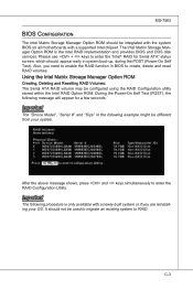
... screen, which should be used to migrate an existing system to enter the "Intel® RAID for a few seconds: Important The "Drvice Model", "Serial #" and "Size" in BIOS to enter the RAID Configuration Utility. MS-7583 BIOS Configuration The Intel Matrix Storage Manager Option ROM should appear early in system boot-up, during the POST (Power-On Self Test). Using the Intel Matrix Stroage Manager Option ROM Creating, Deleting and Resetting RAID Volumes: The Serial ATA RAID...
... screen, which should be used to migrate an existing system to enter the "Intel® RAID for a few seconds: Important The "Drvice Model", "Serial #" and "Size" in BIOS to enter the RAID Configuration Utility. MS-7583 BIOS Configuration The Intel Matrix Storage Manager Option ROM should appear early in system boot-up, during the POST (Power-On Self Test). Using the Intel Matrix Stroage Manager Option ROM Creating, Deleting and Resetting RAID Volumes: The Serial ATA RAID...

User Guide
Page 118
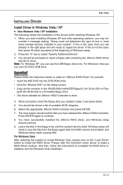
... can use the USB floppy drive only. Select the appropriate Intel RAID controller and press ENTER. 8. C-10 You should confirm that you can use CD/ DVD/ USB drive. Important Please follow the instruction below to install a third party SCSI or RAID driver. 5. The next screen should be shown a list of Windows setup. 2. dows setup should be prompted to insert a floppy disk containing the Intel® RAID driver into the DVD-ROM drive. • Click the "Browse DVD" on "Load Driver" button...
... can use the USB floppy drive only. Select the appropriate Intel RAID controller and press ENTER. 8. C-10 You should confirm that you can use CD/ DVD/ USB drive. Important Please follow the instruction below to install a third party SCSI or RAID driver. 5. The next screen should be shown a list of Windows setup. 2. dows setup should be prompted to insert a floppy disk containing the Intel® RAID driver into the DVD-ROM drive. • Click the "Browse DVD" on "Load Driver" button...
User Guide
Page 147
... the case, then you can use CD/ DVD/ USB drive. Note: For Windows XP, you have successfully installed the JMicron RAID driver, and Windows setup should be prompted to insert a floppy disk containing the JMicron RAID driver into the DVD-ROM drive. • Click the "Browse DVD" on the "Load Driver" button to install the RAID driver. Press ENTER again to select "Specify Additional Device". 3. You have selected the JMicron RAID controller. counter a message stating, "Setup could not determine the type...
... the case, then you can use CD/ DVD/ USB drive. Note: For Windows XP, you have successfully installed the JMicron RAID driver, and Windows setup should be prompted to insert a floppy disk containing the JMicron RAID driver into the DVD-ROM drive. • Click the "Browse DVD" on the "Load Driver" button to install the RAID driver. Press ENTER again to select "Specify Additional Device". 3. You have selected the JMicron RAID controller. counter a message stating, "Setup could not determine the type...


