User Guide
Page 2
...XP are registered trademarks of M ICRO-STAR INTERNATIONAL. Award® is a registered trademark of Intel Corporation. func=service Contact our technical staff at: http://ocss.msi.com.tw ii NVIDIA, the NVIDIA logo, DualNet, and nForce are registered trademarks of Novell, Inc. Netware® is a registered trademark of NVIDIA Corporation in... Technical Support If a problem arises with your place of International Business Machines Corporation. Alternatively, please try the following help resources for FAQ, technical guide, BIOS updates, driver updates, and other countries.
...XP are registered trademarks of M ICRO-STAR INTERNATIONAL. Award® is a registered trademark of Intel Corporation. func=service Contact our technical staff at: http://ocss.msi.com.tw ii NVIDIA, the NVIDIA logo, DualNet, and nForce are registered trademarks of Novell, Inc. Netware® is a registered trademark of NVIDIA Corporation in... Technical Support If a problem arises with your place of International Business Machines Corporation. Alternatively, please try the following help resources for FAQ, technical guide, BIOS updates, driver updates, and other countries.
User Guide
Page 8
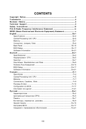
... ...En-1 Specifications ...En-2 Central Processing Unit: CPU En-5 Memory ...En-7 Connectors, Jumpers, Slots En-9 Back Panel ...En-15 BIOS Setup ...En-17 Software Information En-21 Deutsch ...De-1 Spezifikationen De-2 Hauptprozessor: CPU De-5 Speicher ...De-7 Anschlüsse, Steckbr...Anschlusspaneel De-15 BIOS Setup ...De-17 Software-Information De-21 Français ...Fr-1 Spécificités ...Fr-2 Central Processing Unit: CPU Fr-5 Mémoire ...Fr-7 Connecteurs, Cavaliers, Slots Fr-9 Panneau Arrière Fr-15 Configuration du BIOS Fr-17 Information de Logiciel Fr-21 Ru-1 ...
... ...En-1 Specifications ...En-2 Central Processing Unit: CPU En-5 Memory ...En-7 Connectors, Jumpers, Slots En-9 Back Panel ...En-15 BIOS Setup ...En-17 Software Information En-21 Deutsch ...De-1 Spezifikationen De-2 Hauptprozessor: CPU De-5 Speicher ...De-7 Anschlüsse, Steckbr...Anschlusspaneel De-15 BIOS Setup ...De-17 Software-Information De-21 Français ...Fr-1 Spécificités ...Fr-2 Central Processing Unit: CPU Fr-5 Mémoire ...Fr-7 Connecteurs, Cavaliers, Slots Fr-9 Panneau Arrière Fr-15 Configuration du BIOS Fr-17 Information de Logiciel Fr-21 Ru-1 ...
User Guide
Page 14
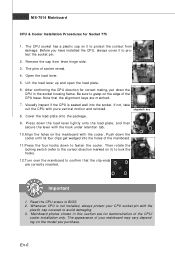
Be sure to protect the contact from lever hinge side. 3. Press down the CPU in the socket housing frame. Mainboard photos shown in BIOS. 2. Remove the cap from damage. After confirming the CPU direction for demonstration of the mainboard. 11.Press the four hooks down the cooler until its ...
Be sure to protect the contact from lever hinge side. 3. Press down the CPU in the socket housing frame. Mainboard photos shown in BIOS. 2. Remove the cap from damage. After confirming the CPU direction for demonstration of the mainboard. 11.Press the four hooks down the cooler until its ...
User Guide
Page 20
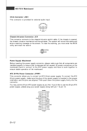
...ensure that all components are aligned. To clear the warning, you to use the 20-pin ATX power supply as you 'd like . ATX 24-Pin Power Connector: JPWR1 This connector allows you must enter the BIOS utility and clear the record. 1 CINTRU 2 GND Power Supply Attachment Before inserting the power ...supply connector, always make sure the plug of the m ainboard. If you like to connect an ATX 24-pin power supply. You may use the ...
...ensure that all components are aligned. To clear the warning, you to use the 20-pin ATX power supply as you 'd like . ATX 24-Pin Power Connector: JPWR1 This connector allows you must enter the BIOS utility and clear the record. 1 CINTRU 2 GND Power Supply Attachment Before inserting the power ...supply connector, always make sure the plug of the m ainboard. If you like to connect an ATX 24-pin power supply. You may use the ...
User Guide
Page 22
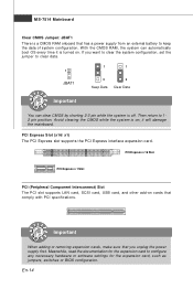
it is turned on. Then return to configure any necessary hardware or software settings for the expansion card, such as jumpers, switches or BIOS configuration. PCI Express x 16 Slot PCI Express x 1 Slot PCI (Peripheral Component Interconnect) Slot The PCI slot supports LAN card, SCSI card, USB card, and other ...
it is turned on. Then return to configure any necessary hardware or software settings for the expansion card, such as jumpers, switches or BIOS configuration. PCI Express x 16 Slot PCI Express x 1 Slot PCI (Peripheral Component Interconnect) Slot The PCI slot supports LAN card, SCSI card, USB card, and other ...

User Guide
Page 25
...default settings for optimum use. Therefore, the description may need to run the Setup program when: * An error message appears on the BIOS Setup program and allows you to run BIOS SETUP. * You want to configure the system for customized features. En-17 Important 1.The items under each... BIOS category described in the format: A7514IMS V1.0 051508 where: 1st digit refers to BIOS maker as A = AMI, W = AWARD, and P = PHOENIX. 2nd - 5th digit refers to the model number. 6th refers to ...
...default settings for optimum use. Therefore, the description may need to run the Setup program when: * An error message appears on the BIOS Setup program and allows you to run BIOS SETUP. * You want to configure the system for customized features. En-17 Important 1.The items under each... BIOS category described in the format: A7514IMS V1.0 051508 where: 1st digit refers to BIOS maker as A = AMI, W = AWARD, and P = PHOENIX. 2nd - 5th digit refers to the model number. 6th refers to ...
User Guide
Page 26
... m enu, the first menu you find a right pointer symbol (as shown in the right view) appears to the left of the screen. General Help The BIOS setup program provides a General Help screen. The on-line description of the highlighted setup function is the Main Menu. Sub-Menu If you will start...
... m enu, the first menu you find a right pointer symbol (as shown in the right view) appears to the left of the screen. General Help The BIOS setup program provides a General Help screen. The on-line description of the highlighted setup function is the Main Menu. Sub-Menu If you will start...
User Guide
Page 27
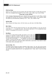
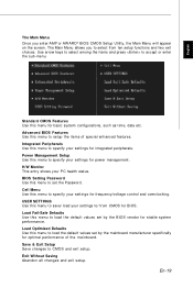
... Menu Once you to select from CMOS for basic system configurations, such as time, date etc. Integrated Peripherals Use this menu to set the Password. BIOS Setting Password Use this menu to accept or enter the sub-menu. Load Fail-Safe Defaults Use this menu to specify your settings for power... SETTINGS Use this menu to / from ten setup functions and two exit choices. The Main Menu allows you enter AMI® or AW ARD® BIOS CMOS Setup Utility, the Main Menu will appear on the screen. Power Management Setup Use this menu to save/ load your settings to specify your...
... Menu Once you to select from CMOS for basic system configurations, such as time, date etc. Integrated Peripherals Use this menu to set the Password. BIOS Setting Password Use this menu to accept or enter the sub-menu. Load Fail-Safe Defaults Use this menu to specify your settings for power... SETTINGS Use this menu to / from ten setup functions and two exit choices. The Main Menu allows you enter AMI® or AW ARD® BIOS CMOS Setup Utility, the Main Menu will appear on the screen. Power Management Setup Use this menu to save/ load your settings to specify your...
User Guide
Page 28
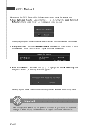
.... 2. Adjust the Date, Tim e fields. 3. Important The configuration above are for general use only. En-20 MS-7514 Mainboard W hen enter the BIOS Setup utility, follow the processes below appears: Select [Ok] and press Enter to save the configurations and exit... BIOS Setup utility. If you need the detailed settings of BIOS, please see the manual in English version on MSI website. Load Optimized Defaults : Use control keys (↑↓ ) to enter the Standard CMOS Features...
.... 2. Adjust the Date, Tim e fields. 3. Important The configuration above are for general use only. En-20 MS-7514 Mainboard W hen enter the BIOS Setup utility, follow the processes below appears: Select [Ok] and press Enter to save the configurations and exit... BIOS Setup utility. If you need the detailed settings of BIOS, please see the manual in English version on MSI website. Load Optimized Defaults : Use control keys (↑↓ ) to enter the Standard CMOS Features...
User Guide
Page 29
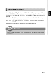
Utility m enu - Important Please visit the MSI website to activate the device. En-21 Install the driver by your desire and to get the latest drivers and BIOS for better system performance. W ebSite menu- The W ebSite menu shows the necessary websites. The Utility menu shows the software applications that is included in the...
Utility m enu - Important Please visit the MSI website to activate the device. En-21 Install the driver by your desire and to get the latest drivers and BIOS for better system performance. W ebSite menu- The W ebSite menu shows the necessary websites. The Utility menu shows the software applications that is included in the...
User Manual
Page 2
.../XP/Vista are registered trademarks or trademarks of NVIDIA Corporation in the United States and/or other information: http://global.msi.com.tw/index.php? Visit the MSI website for FAQ, technical guide, BIOS updates, driver updates, and other countries. We take every care in the preparation of this document is a registered trademark...
.../XP/Vista are registered trademarks or trademarks of NVIDIA Corporation in the United States and/or other information: http://global.msi.com.tw/index.php? Visit the MSI website for FAQ, technical guide, BIOS updates, driver updates, and other countries. We take every care in the preparation of this document is a registered trademark...
User Manual
Page 8
... Processing Unit 2-3 Memory ...2-7 Power Supply ...2-9 Back Panel ...2-10 Connectors ...2-12 Jumper ...2-19 Slots ...2-20 Chapter 3 BIOS Setup 3-1 Entering Setup ...3-2 The Main Menu ...3-4 Standard CMOS Features 3-6 Advanced BIOS Features 3-9 Integrated Peripherals 3-12 Power Management Setup 3-15 H/W Monitor ...3-18 BIOS Setting Password 3-19 Cell Menu ...3-20 USERSETTINGS 3-24 Load Fail-Safe/ Optimized Defaults 3-25 Appendix...
... Processing Unit 2-3 Memory ...2-7 Power Supply ...2-9 Back Panel ...2-10 Connectors ...2-12 Jumper ...2-19 Slots ...2-20 Chapter 3 BIOS Setup 3-1 Entering Setup ...3-2 The Main Menu ...3-4 Standard CMOS Features 3-6 Advanced BIOS Features 3-9 Integrated Peripherals 3-12 Power Management Setup 3-15 H/W Monitor ...3-18 BIOS Setting Password 3-19 Cell Menu ...3-20 USERSETTINGS 3-24 Load Fail-Safe/ Optimized Defaults 3-25 Appendix...
User Manual
Page 9
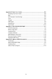
Appendix B Dual Core Center B-1 Activating Dual Core Center B-2 Main ...B-3 DOT (Dynamic OverClocking B-5 Clock ...B-6 Voltage ...B-7 FAN Speed ...B-8 Temperature ...B-9 User Profile ...B-10 Appendix C Intel ICH10R SATA RAID C-1 ICH10R Introduction C-2 BIOS Configuration C-3 Installing Driver C-10 Installing Software C-12 RAID Migration Instructions C-16 Recovery Volume Creation C-23 Degraded RAID Array C-27 Appendix D JM icron RAID Introduction D-1 Introduction ...D-2 JMicron RAID BIOS Utility D-3 Installing Driver D-11 JMicron Raid Configurer D-13 ix
Appendix B Dual Core Center B-1 Activating Dual Core Center B-2 Main ...B-3 DOT (Dynamic OverClocking B-5 Clock ...B-6 Voltage ...B-7 FAN Speed ...B-8 Temperature ...B-9 User Profile ...B-10 Appendix C Intel ICH10R SATA RAID C-1 ICH10R Introduction C-2 BIOS Configuration C-3 Installing Driver C-10 Installing Software C-12 RAID Migration Instructions C-16 Recovery Volume Creation C-23 Degraded RAID Array C-27 Appendix D JM icron RAID Introduction D-1 Introduction ...D-2 JMicron RAID BIOS Utility D-3 Installing Driver D-11 JMicron Raid Configurer D-13 ix
User Manual
Page 20
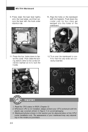
... fasten the cooler. locking switch Important 1. Turn over the mainboard to avoid damaging. 3. The appearance of the CPU/ cooler installation only. Mainboard photos shown in BIOS (Chapter 3). 2. Push down to lock the h ook s . 12. Press the four hooks down the cooler until its four clips get wedged into the holes of...
... fasten the cooler. locking switch Important 1. Turn over the mainboard to avoid damaging. 3. The appearance of the CPU/ cooler installation only. Mainboard photos shown in BIOS (Chapter 3). 2. Push down to lock the h ook s . 12. Press the four hooks down the cooler until its four clips get wedged into the holes of...

User Manual
Page 28
... screen. CPUFAN supports fan control. If the chassis is Ground and should be connected to the +12V; To clear the warning, you must enter the BIOS utility and clear the record. Please refer to the chassis intrusion switch cable. Fan cooler set with +12V. W hen connecting the wire to the connectors...
... screen. CPUFAN supports fan control. If the chassis is Ground and should be connected to the +12V; To clear the warning, you must enter the BIOS utility and clear the record. Please refer to the chassis intrusion switch cable. Fan cooler set with +12V. W hen connecting the wire to the connectors...
User Manual
Page 34
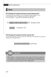
Meanwhile, read the documentation for the expansion card, such as jumpers, switches or BIOS configuration. 2-20 PCI Express x16 Slot PCI Express x 1 Slot PCI (Peripheral Component Interconnect) Slot The PCI slot supports LAN card, SCSI card, USB card, and ...
Meanwhile, read the documentation for the expansion card, such as jumpers, switches or BIOS configuration. 2-20 PCI Express x16 Slot PCI Express x 1 Slot PCI (Peripheral Component Interconnect) Slot The PCI slot supports LAN card, SCSI card, USB card, and ...

User Manual
Page 36
Chapter 3 BIOS Setup BIOS Setup This chapter provides information on the screen during the system booting up, and requests you to change the default settings for optimum use. You may need to run the Setup program when: ² An error message appears on the BIOS Setup program and allows you to run SETUP. ² You want to configure the system for customized features. 3-1
Chapter 3 BIOS Setup BIOS Setup This chapter provides information on the screen during the system booting up, and requests you to change the default settings for optimum use. You may need to run the Setup program when: ² An error message appears on the BIOS Setup program and allows you to run SETUP. ² You want to configure the system for customized features. 3-1

User Manual
Page 37
... Setup, restart the system by simultaneously pressing , , and keys. V1.0 refers to the BIOS version. 040108 refers to the date this chapter are under each BIOS category described in the format: A7514IMS V1.0 040108 where: 1st digit refers to BIOS maker as A = AMI, W = AWARD, and P = PHOENIX. 2nd - 5th digit refers ... appears on the computer and the system will start POST (Power On Self Test) process. You may be slightly different from the latest BIOS and should be held for better system performance. MS-7514 Mainboard Entering Setup Power on the screen, press key to enter Setup.
... Setup, restart the system by simultaneously pressing , , and keys. V1.0 refers to the BIOS version. 040108 refers to the date this chapter are under each BIOS category described in the format: A7514IMS V1.0 040108 where: 1st digit refers to BIOS maker as A = AMI, W = AWARD, and P = PHOENIX. 2nd - 5th digit refers ... appears on the computer and the system will start POST (Power On Self Test) process. You may be slightly different from the latest BIOS and should be held for better system performance. MS-7514 Mainboard Entering Setup Power on the screen, press key to enter Setup.

User Manual
Page 38
Main Menu The main menu lists the setup functions you can use the arrow keys ( ↑↓ ) to select the item. General Help The BIOS setup program provides a General Help screen. You can make changes Load Optimized Defaults Save all the CMOS changes and exit Getting Help After entering the ... that means a sub-menu can call up this screen from this field. The on-line description of the highlighted setup function is the Main Menu. BIOS Setup Control Keys Enter> Move to the previous item Move to the next item Move to the item in the left hand Move to the...
Main Menu The main menu lists the setup functions you can use the arrow keys ( ↑↓ ) to select the item. General Help The BIOS setup program provides a General Help screen. You can make changes Load Optimized Defaults Save all the CMOS changes and exit Getting Help After entering the ... that means a sub-menu can call up this screen from this field. The on-line description of the highlighted setup function is the Main Menu. BIOS Setup Control Keys Enter> Move to the previous item Move to the next item Move to the item in the left hand Move to the...

User Manual
Page 39
... Management Setup Use this menu to set the password for frequency/voltage control and overclocking. BIOS Setting Password Use this menu to / from CMOS for power management. Advanced BIOS Features Use this menu to specify your settings for BIOS. 3-4 USER SETTINGS Use this menu to specify your settings to setup the items of...
... Management Setup Use this menu to set the password for frequency/voltage control and overclocking. BIOS Setting Password Use this menu to / from CMOS for power management. Advanced BIOS Features Use this menu to specify your settings for BIOS. 3-4 USER SETTINGS Use this menu to specify your settings to setup the items of...


