User Guide
Page 2
...of American Megatrends Inc. Award® is a registered trademark of AMD Corporation. Visit the MSI website for further guidance. func=service Contact our technical staff at: http://ocss.msi.com.tw ii AMI® is a registered trademark of its contents. Netware® is... for FAQ, technical guide, BIOS updates, driver updates, and other countries. We take every care in the preparation of this document is the intellectual property of Novell, Inc. Revision History Revision V1.0 Revision History First release for P45 Diamond Date March 2008 Technical Support ...
...of American Megatrends Inc. Award® is a registered trademark of AMD Corporation. Visit the MSI website for further guidance. func=service Contact our technical staff at: http://ocss.msi.com.tw ii AMI® is a registered trademark of its contents. Netware® is... for FAQ, technical guide, BIOS updates, driver updates, and other countries. We take every care in the preparation of this document is the intellectual property of Novell, Inc. Revision History Revision V1.0 Revision History First release for P45 Diamond Date March 2008 Technical Support ...

User Guide
Page 8
... ...2-22 Slots ...2-23 LED Status Indicators 2-27 Water cooling accessories installation 2-29 Chapter 3 BIOS Setup 3-1 Entering Setup ...3-2 The Main Menu ...3-4 Standard CMOS Features 3-6 Advanced BIOS Features 3-9 Integrated Peripherals 3-12 Power Management Setup 3-14 H/W Monitor ...3-17 Green Power ...3-18 BIOS Setting Password 3-19 Cell Menu ...3-20 Load Fail-Safe/ Optimized Defaults 3-25 Appendix A X-Fi...
... ...2-22 Slots ...2-23 LED Status Indicators 2-27 Water cooling accessories installation 2-29 Chapter 3 BIOS Setup 3-1 Entering Setup ...3-2 The Main Menu ...3-4 Standard CMOS Features 3-6 Advanced BIOS Features 3-9 Integrated Peripherals 3-12 Power Management Setup 3-14 H/W Monitor ...3-17 Green Power ...3-18 BIOS Setting Password 3-19 Cell Menu ...3-20 Load Fail-Safe/ Optimized Defaults 3-25 Appendix A X-Fi...
User Guide
Page 9
... Core Center B-1 Activating Dual Core Center B-2 Main ...B-3 DOT (Dynamic OverClocking B-5 Clock ...B-6 Voltage ...B-7 FAN Speed ...B-8 Temperature ...B-9 User Profile ...B-10 Appendix C Intel ICH10R SATA RAID C-1 ICH10R Introduction C-2 BIOS Configuration C-3 Installing Driver ...C-9 Installing Software C-11 RAID Migration Instructions C-16 Recovery Volume Creation C-23 Degraded RAID Array C-27 Appendix D JM icron RAID Introduction D-1 Introduction ...D-2 JMicron...
... Core Center B-1 Activating Dual Core Center B-2 Main ...B-3 DOT (Dynamic OverClocking B-5 Clock ...B-6 Voltage ...B-7 FAN Speed ...B-8 Temperature ...B-9 User Profile ...B-10 Appendix C Intel ICH10R SATA RAID C-1 ICH10R Introduction C-2 BIOS Configuration C-3 Installing Driver ...C-9 Installing Software C-11 RAID Migration Instructions C-16 Recovery Volume Creation C-23 Degraded RAID Array C-27 Appendix D JM icron RAID Introduction D-1 Introduction ...D-2 JMicron...

User Guide
Page 21
..., and then secure the lever with the heatsink. Align the holes on the mainboard with the hook under retention tab. 10. Mainboard photos shown in BIOS (Chapter 3). 2. locking switch Mainboard Hook Important 1. Whenever CPU is not installed, always protect your mainboard may vary depending on it) to confirm that the clip...
..., and then secure the lever with the heatsink. Align the holes on the mainboard with the hook under retention tab. 10. Mainboard photos shown in BIOS (Chapter 3). 2. locking switch Mainboard Hook Important 1. Whenever CPU is not installed, always protect your mainboard may vary depending on it) to confirm that the clip...

User Guide
Page 32
... warning message on -board, you must use a specially designed fan with speed sensor to the +12V; To clear the warning, you must enter the BIOS utility and clear the record. GND CINTRU 1 2 JCI1 2-17 Please refer to the actual CPU temperature. 3. If the mainboard has a System Hardware Monitor...W hen connecting the wire to the connectors, always note that the red wire is Ground and should be connected to take advantage of BIOS and install Dual Core Center utility that will automatically control the CPU fan speed according to the recommended CPU fans at processor's official website ...
... warning message on -board, you must use a specially designed fan with speed sensor to the +12V; To clear the warning, you must enter the BIOS utility and clear the record. GND CINTRU 1 2 JCI1 2-17 Please refer to the actual CPU temperature. 3. If the mainboard has a System Hardware Monitor...W hen connecting the wire to the connectors, always note that the red wire is Ground and should be connected to take advantage of BIOS and install Dual Core Center utility that will automatically control the CPU fan speed according to the recommended CPU fans at processor's official website ...

User Guide
Page 38
... card. The PCI Express 2.0x 16 supports up to configure any necessary hardware or software settings for the expansion card, such as jumpers, switches or BIOS configuration. 2-23
... card. The PCI Express 2.0x 16 supports up to configure any necessary hardware or software settings for the expansion card, such as jumpers, switches or BIOS configuration. 2-23

User Guide
Page 39
... pronounced I-R-Q, are typically connected to configure any necessary hardware or software settings for the expansion card to the PCI bus pins as jumpers, switches or BIOS configuration.
... pronounced I-R-Q, are typically connected to configure any necessary hardware or software settings for the expansion card to the PCI bus pins as jumpers, switches or BIOS configuration.

User Guide
Page 40
... Radeon (CrossFire Ready) graphics card from the same series. Make sure that allows the power of the same brand and specifications; Mainboard photos shown in BIOS by ATI that you have installed two graphics cards, only the video outputs on both PCIE x16 slots. 3. Install the CrossFire Edition graphics card in...
... Radeon (CrossFire Ready) graphics card from the same series. Make sure that allows the power of the same brand and specifications; Mainboard photos shown in BIOS by ATI that you have installed two graphics cards, only the video outputs on both PCIE x16 slots. 3. Install the CrossFire Edition graphics card in...

User Guide
Page 43
... various patterns. Green light Red light Off LED Signal Description System Power ON The D-LED will light Green color. Testing VGA BIOS This will light Red color. Testing Base and Extended Memory Testing base memory from 240K to all ISA. Initializing Keyboard Controller. Operating... System Booting 2-28 These LEDs will start writing VGA sign-on message to the screen. Decompressing BIOS image to identify system problems through 16 various combinations of LED signals. The D-LED will set low stack and boot via INT ...
... various patterns. Green light Red light Off LED Signal Description System Power ON The D-LED will light Green color. Testing VGA BIOS This will light Red color. Testing Base and Extended Memory Testing base memory from 240K to all ISA. Initializing Keyboard Controller. Operating... System Booting 2-28 These LEDs will start writing VGA sign-on message to the screen. Decompressing BIOS image to identify system problems through 16 various combinations of LED signals. The D-LED will set low stack and boot via INT ...

User Guide
Page 47
You may need to run the Setup program when: ² An error message appears on the BIOS Setup program and allows you to run SETUP. ² You want to configure the system for customized features. 3-1 Chapter 3 BIOS Setup BIOS Setup This chapter provides information on the screen during the system booting up, and requests you to change the default settings for optimum use.
You may need to run the Setup program when: ² An error message appears on the BIOS Setup program and allows you to run SETUP. ² You want to configure the system for customized features. 3-1 Chapter 3 BIOS Setup BIOS Setup This chapter provides information on the screen during the system booting up, and requests you to change the default settings for optimum use.

User Guide
Page 48
...may be slightly different from the latest BIOS and should be held for better system performance. Upon boot-up, the 1st line appearing after the memory count is usually in this BIOS was released. 3-2 It is the BIOS version. The items under each BIOS category described in the format: A7516IMS V1....0 030808 where: 1st digit refers to BIOS maker as A = AMI, W = AWARD, and P = PHOENIX. 2nd - 5th...
...may be slightly different from the latest BIOS and should be held for better system performance. Upon boot-up, the 1st line appearing after the memory count is usually in this BIOS was released. 3-2 It is the BIOS version. The items under each BIOS category described in the format: A7516IMS V1....0 030808 where: 1st digit refers to BIOS maker as A = AMI, W = AWARD, and P = PHOENIX. 2nd - 5th...

User Guide
Page 49
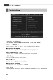
... Help screen lists the appropriate keys to . Main Menu The main menu lists the setup functions you can call up this field. General Help The BIOS setup program provides a General Help screen. You can use the control keys to enter values and move from field to select the item. A sub-menu... the Help screen. 3-3 Press to the main menu, just press the . If you can use the arrow keys ( ↑↓ ) to field within a sub-menu. BIOS Setup Control Keys Enter> Move to the previous item Move to the next item Move to the item in the left of the screen.
... Help screen lists the appropriate keys to . Main Menu The main menu lists the setup functions you can call up this field. General Help The BIOS setup program provides a General Help screen. You can use the control keys to enter values and move from field to select the item. A sub-menu... the Help screen. 3-3 Press to the main menu, just press the . If you can use the arrow keys ( ↑↓ ) to field within a sub-menu. BIOS Setup Control Keys Enter> Move to the previous item Move to the next item Move to the item in the left of the screen.
User Guide
Page 50
...menu to specify your settings for frequency/voltage control and overclocking. 3-4 Power Management Setup Use this menu to specify your settings for power management. BIOS Setting Password Use this menu to specify your PC health status. MS-7516 Mainboard The Main Menu Standard CMOS Features Use this menu for... BIOS. Cell Menu Use this menu to set the password for basic system configurations, such as time, date etc. H/W Monitor This entry shows your ...
...menu to specify your settings for frequency/voltage control and overclocking. 3-4 Power Management Setup Use this menu to specify your settings for power management. BIOS Setting Password Use this menu to specify your PC health status. MS-7516 Mainboard The Main Menu Standard CMOS Features Use this menu for... BIOS. Cell Menu Use this menu to set the password for basic system configurations, such as time, date etc. H/W Monitor This entry shows your ...

User Guide
Page 51
Save & Exit Setup Save changes to save or load settings. BIOS Setup User Settings Use this menu to load the default values set by the mainboard manufacturer specifically for stable system performance. Load Fail-Safe Defaults Use this menu to load the default values set by the BIOS vendor for optimal performance of the mainboard. Exit Without Saving Abandon all changes and exit setup. 3-5 Load Optimized Defaults Use this menu to CMOS and exit setup.
Save & Exit Setup Save changes to save or load settings. BIOS Setup User Settings Use this menu to load the default values set by the mainboard manufacturer specifically for stable system performance. Load Fail-Safe Defaults Use this menu to load the default values set by the BIOS vendor for optimal performance of the mainboard. Exit Without Saving Abandon all changes and exit setup. 3-5 Load Optimized Defaults Use this menu to CMOS and exit setup.

User Guide
Page 52
... system time that you want (usually the current date). day Day of the week, from Jan. month The month from Sun to Sat, determined by BIOS. through Dec. date The date from 1 to 31 can be keyed by users. year The year can be adjusted by numeric function keys. MS-7516...
... system time that you want (usually the current date). day Day of the week, from Jan. month The month from Sun to Sat, determined by BIOS. through Dec. date The date from 1 to 31 can be keyed by users. year The year can be adjusted by numeric function keys. MS-7516...

User Guide
Page 53
..., 5.25 in.], [1.2M, 5.25 in.], [720K, 3.5 in.], [1.44M, 3.5 in.], [2.88M, 3.5 in.]. This allows you an opportunity to a safe place before the hard disk becomes offline. BIOS Setup Device / Vender / Size It will stop if an error is a utility that monitors your disk status to predict hard disk failure. Setting to Auto...
..., 5.25 in.], [1.2M, 5.25 in.], [720K, 3.5 in.], [1.44M, 3.5 in.], [2.88M, 3.5 in.]. This allows you an opportunity to a safe place before the hard disk becomes offline. BIOS Setup Device / Vender / Size It will stop if an error is a utility that monitors your disk status to predict hard disk failure. Setting to Auto...

User Guide
Page 54
This sub-menu shows the CPU information, BIOS version and memory status of your system (read only). 3-8 MS-7516 Mainboard System Information Press to enter the sub-menu, and the following screen appears.
This sub-menu shows the CPU information, BIOS version and memory status of your system (read only). 3-8 MS-7516 Mainboard System Information Press to enter the sub-menu, and the following screen appears.

User Guide
Page 55
... keys on the numeric keypad. IOAPIC Function This field is powered on. Password Check You need to reset the password in APIC mode. Advanced BIOS Features BIOS Setup Full Screen LOGO Display This item enables you to select which version to [On] will turn on the Num Lock key when the system...
... keys on the numeric keypad. IOAPIC Function This field is powered on. Password Check You need to reset the password in APIC mode. Advanced BIOS Features BIOS Setup Full Screen LOGO Display This item enables you to select which version to [On] will turn on the Num Lock key when the system...

User Guide
Page 57
if the system fails to boot from other device. Trusted Computing Press to enter the sub-menu and the following screen appears: 1st/ 2nd/ 3rd/ 4th Boot Device The items allow you to enable/disable the TCG/TPM. 3-11 BIOS Setup Boot Sequence Press to enter the sub-menu and the following screen appears: TCG/TPM SUPPORT This setting allows you to set the first/ second/ third/ fourth boot device where BIOS attempts to load the disk operating system. Boot From Other Device Setting the option to [Yes] allows the system to try to boot from the 1st/ 2nd/ 3rd boot device.
if the system fails to boot from other device. Trusted Computing Press to enter the sub-menu and the following screen appears: 1st/ 2nd/ 3rd/ 4th Boot Device The items allow you to enable/disable the TCG/TPM. 3-11 BIOS Setup Boot Sequence Press to enter the sub-menu and the following screen appears: TCG/TPM SUPPORT This setting allows you to set the first/ second/ third/ fourth boot device where BIOS attempts to load the disk operating system. Boot From Other Device Setting the option to [Yes] allows the system to try to boot from the 1st/ 2nd/ 3rd boot device.

User Guide
Page 59
... the sub-menu and the following screen appears: COM Port 1 Select an address and corresponding interrupt for SATA devices. I/O Device Configuration Press to IDE drives. BIOS Setup RAID Mode This item allows you to enable/ disable BIOS to used to enable or disable the SATA controller.
... the sub-menu and the following screen appears: COM Port 1 Select an address and corresponding interrupt for SATA devices. I/O Device Configuration Press to IDE drives. BIOS Setup RAID Mode This item allows you to enable/ disable BIOS to used to enable or disable the SATA controller.


