User Guide
Page 8
......2-11 Connectors ...2-12 Jumper ...2-19 Button ...2-20 Slots ...2-21 LED Status Indicators 2-23 Chapter 3 BIOS Setup 3-1 Entering Setup ...3-2 The Main Menu ...3-4 Standard CMOS Features 3-6 Advanced BIOS Features 3-9 Integrated Peripherals 3-12 Power Management Setup 3-14 PNP/PCI Configurations 3-17 H/W Monitor ...3-19... Cell Menu ...3-20 Load Fail-Safe/ Optimized Defaults 3-26 BIOS Setting Password 3-27 Appendix A Realtek ALC888/888T Audio A-1 Installation for W indows 2000/XP A-2 Installing the Realtek HD ...
......2-11 Connectors ...2-12 Jumper ...2-19 Button ...2-20 Slots ...2-21 LED Status Indicators 2-23 Chapter 3 BIOS Setup 3-1 Entering Setup ...3-2 The Main Menu ...3-4 Standard CMOS Features 3-6 Advanced BIOS Features 3-9 Integrated Peripherals 3-12 Power Management Setup 3-14 PNP/PCI Configurations 3-17 H/W Monitor ...3-19... Cell Menu ...3-20 Load Fail-Safe/ Optimized Defaults 3-26 BIOS Setting Password 3-27 Appendix A Realtek ALC888/888T Audio A-1 Installation for W indows 2000/XP A-2 Installing the Realtek HD ...
User Guide
Page 9
Hardware Setup A-18 Appendix B Dual Core Center B-1 Activating Dual Core Center B-2 Main ...B-2 DOT (Dynamic OverClocking B-5 Clock ...B-6 Voltage ...B-7 FAN Speed ...B-8 Temperature ...B-9 User Profile ...B-10 Appendix C Intel ICH9R SATA RAID (optional C-1 ICH9R Introduction C-2 BIOS Configuration C-3 Installing Driver ...C-9 Installing Software C-11 RAID Migration Instructions C-15 Degraded RAID Array C-22 ix
Hardware Setup A-18 Appendix B Dual Core Center B-1 Activating Dual Core Center B-2 Main ...B-2 DOT (Dynamic OverClocking B-5 Clock ...B-6 Voltage ...B-7 FAN Speed ...B-8 Temperature ...B-9 User Profile ...B-10 Appendix C Intel ICH9R SATA RAID (optional C-1 ICH9R Introduction C-2 BIOS Configuration C-3 Installing Driver ...C-9 Installing Software C-11 RAID Migration Instructions C-15 Degraded RAID Array C-22 ix
User Guide
Page 20
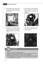
... the cooler. Mainboard photos shown in this section are correctly inserted. The appearance of your CPU socket pin with the plastic cap covered (shown in BIOS (Chapter 3). 2. Whenever CPU is not installed, always protect your mainboard may vary depending on the model you purchase. 2-6 MS-7345 Mainboard 9. Align the holes on...
... the cooler. Mainboard photos shown in this section are correctly inserted. The appearance of your CPU socket pin with the plastic cap covered (shown in BIOS (Chapter 3). 2. Whenever CPU is not installed, always protect your mainboard may vary depending on the model you purchase. 2-6 MS-7345 Mainboard 9. Align the holes on...
User Guide
Page 28
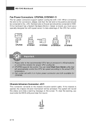
... to the connectors, always note that will automatically control the CPU fan speed according to the +12V; To clear the warning, you must enter the BIOS utility and clear the record. Please refer to the chassis intrusion switch cable. Chassis Intrusion Connector: JCI1 This connector connects to the recommended CPU fans...
... to the connectors, always note that will automatically control the CPU fan speed according to the +12V; To clear the warning, you must enter the BIOS utility and clear the record. Please refer to the chassis intrusion switch cable. Chassis Intrusion Connector: JCI1 This connector connects to the recommended CPU fans...
User Guide
Page 35
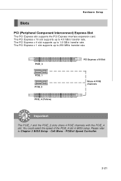
... transfer rate. The PCI Express x 1 slot supports up to 250 MB/s transfer rate. You could select the speed of the PCIE_4 slot in BIOS setup. PCIEx4 Speed Controller. 2-21 PCIE_3 PCIE_1 PCIE_2 PCIE_4 (Yellow) PCI Express x16 Slot Share 4 PCIE channels Important The PCIE_1 and the PCIE_2 ... with the PCIE_4 slot. Please refer to 4.0 GB/s transfer rate. Cell Menu - The PCI Express x 16 slot supports up to Chapter 3 BIOS Setup - Hardware Setup Slots PCI (Peripheral Component Interconnect) Express Slot The PCI Express slot supports the PCI Express interface expansion card.
... transfer rate. The PCI Express x 1 slot supports up to 250 MB/s transfer rate. You could select the speed of the PCIE_4 slot in BIOS setup. PCIEx4 Speed Controller. 2-21 PCIE_3 PCIE_1 PCIE_2 PCIE_4 (Yellow) PCI Express x16 Slot Share 4 PCIE channels Important The PCIE_1 and the PCIE_2 ... with the PCIE_4 slot. Please refer to 4.0 GB/s transfer rate. Cell Menu - The PCI Express x 16 slot supports up to Chapter 3 BIOS Setup - Hardware Setup Slots PCI (Peripheral Component Interconnect) Express Slot The PCI Express slot supports the PCI Express interface expansion card.
User Guide
Page 36
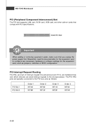
PCI Interrupt Request Routing The IRQ, acronym of interrupt request line and pronounced I-R-Q, are typically connected to the PCI bus pins as jumpers, switches or BIOS configuration. Meanwhile, read the documentation for the expansion card to the microprocessor. The PCI IRQ pins are hardware lines over which devices can send interrupt ...
PCI Interrupt Request Routing The IRQ, acronym of interrupt request line and pronounced I-R-Q, are typically connected to the PCI bus pins as jumpers, switches or BIOS configuration. Meanwhile, read the documentation for the expansion card to the microprocessor. The PCI IRQ pins are hardware lines over which devices can send interrupt ...

User Guide
Page 38
... Group2 Group1 Operating System Booting Then, detect and initialize the video adapter. Group4 Group3 Group2 Group1 Decompressing BIOS image to identify system problems through 16 various combinations of LED signals. Group4 Group3 Group2 Group1 BIOS Sign On This will start writing VGA sign-on message to the screen. Group4 Group3 Group2 Group1... Clock) Group4 Group3 Group2 Group1 Initializing Hard Drive Controller This will start detecting CPU clock, checking type ofvideo onboard. Group4 Group3 Group2 Group1 Testing VGA BIOS This will initialize IDE drive and controller.
... Group2 Group1 Operating System Booting Then, detect and initialize the video adapter. Group4 Group3 Group2 Group1 Decompressing BIOS image to identify system problems through 16 various combinations of LED signals. Group4 Group3 Group2 Group1 BIOS Sign On This will start writing VGA sign-on message to the screen. Group4 Group3 Group2 Group1... Clock) Group4 Group3 Group2 Group1 Initializing Hard Drive Controller This will start detecting CPU clock, checking type ofvideo onboard. Group4 Group3 Group2 Group1 Testing VGA BIOS This will initialize IDE drive and controller.
User Guide
Page 39
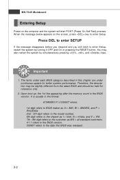
You may need to run SETUP. ² You want to configure the system for customized features. 3-1 Chapter 3 BIOS Setup BIOS Setup This chapter provides information on the screen during the system booting up, and requests you to run the Setup program when: ² An error message appears on the BIOS Setup program and allows you to change the default settings for optimum use.
You may need to run SETUP. ² You want to configure the system for customized features. 3-1 Chapter 3 BIOS Setup BIOS Setup This chapter provides information on the screen during the system booting up, and requests you to run the Setup program when: ² An error message appears on the BIOS Setup program and allows you to change the default settings for optimum use.
User Guide
Page 40
...only. 2. Therefore, the description may also restart the system by turning it OFF and On or pressing the RESET button. It is the BIOS version. V1.1 refers to the BIOS version. 030807 refers to enter Setup, restart the system by simultaneously pressing , , and keys. Press DEL to enter SETUP If the ... refers to the model number. 6th digit refers to the chipset as MS = all standard customers. You may be slightly different from the latest BIOS and should be held for better system performance. Upon boot-up, the 1st line appearing after the memory count is usually in this...
...only. 2. Therefore, the description may also restart the system by turning it OFF and On or pressing the RESET button. It is the BIOS version. V1.1 refers to the BIOS version. 030807 refers to enter Setup, restart the system by simultaneously pressing , , and keys. Press DEL to enter SETUP If the ... refers to the model number. 6th digit refers to the chipset as MS = all standard customers. You may be slightly different from the latest BIOS and should be held for better system performance. Upon boot-up, the 1st line appearing after the memory count is usually in this...
User Guide
Page 41
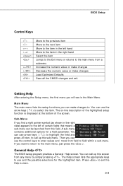
... at the bottom of the screen. A sub-menu contains additional options for the highlighted item. You can call up this field. General Help The BIOS setup program provides a General Help screen. If you can use and the possible selections for a field parameter. The on-line description of the highlighted... menu by simply pressing . Press to call up the sub-menu. You can use the arrow keys ( ↑↓ ) to select the item. BIOS Setup Control Keys Enter> Move to the previous item Move to the next item Move to the item in the right hand Select the item...
... at the bottom of the screen. A sub-menu contains additional options for the highlighted item. You can call up this field. General Help The BIOS setup program provides a General Help screen. If you can use and the possible selections for a field parameter. The on-line description of the highlighted... menu by simply pressing . Press to call up the sub-menu. You can use the arrow keys ( ↑↓ ) to select the item. BIOS Setup Control Keys Enter> Move to the previous item Move to the next item Move to the item in the right hand Select the item...
User Guide
Page 42
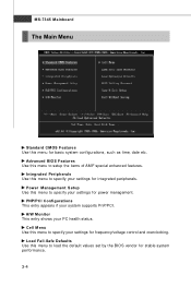
... to setup the items of AMI® special enhanced features. PNP/PCI Configurations This entry appears if your PC health status. Advanced BIOS Features Use this menu to specify your settings for integrated peripherals. Power Management Setup Use this menu to load the default values set ...by the BIOS vendor for stable system performance. 3-4 Load Fail-Safe Defaults Use this menu to specify your settings for power management. H/W Monitor This ...
... to setup the items of AMI® special enhanced features. PNP/PCI Configurations This entry appears if your PC health status. Advanced BIOS Features Use this menu to specify your settings for integrated peripherals. Power Management Setup Use this menu to load the default values set ...by the BIOS vendor for stable system performance. 3-4 Load Fail-Safe Defaults Use this menu to specify your settings for power management. H/W Monitor This ...

User Guide
Page 43
Save & Exit Setup Save changes to CMOS and exit setup. BIOS Setting Password Use this menu to load the default values set the password for optimal performance of the mainboard. Exit Without Saving Abandon all changes and exit setup. 3-5 BIOS Setup Load Optimized Defaults Use this menu to set by the mainboard manufacturer specifically for BIOS.
Save & Exit Setup Save changes to CMOS and exit setup. BIOS Setting Password Use this menu to load the default values set the password for optimal performance of the mainboard. Exit Without Saving Abandon all changes and exit setup. 3-5 BIOS Setup Load Optimized Defaults Use this menu to set by the mainboard manufacturer specifically for BIOS.
User Guide
Page 44
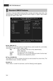
Read-only. SATA1~6 Press to 31 can be keyed by users. date The date from Sun to Sat, determined by BIOS. MS-7345 Mainboard Standard CMOS Features The items in each item. Time (HH:MM :SS) This allows you to set the system to select the ...
Read-only. SATA1~6 Press to 31 can be keyed by users. date The date from Sun to Sat, determined by BIOS. MS-7345 Mainboard Standard CMOS Features The items in each item. Time (HH:MM :SS) This allows you to set the system to select the ...
User Guide
Page 45
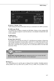
Available options: [None], [360K, 5.25 in.], [1.2M, 5.25 in.], [720K, 3.5 in.], [1.44M, 3.5 in.], [2.88M, 3.5 in.]. 3-7 This gives you to enable or disable the LBA Mode. BIOS Setup Device / Vender / Size It will showing the device information that monitors your disk status to predict hard disk failure. Hard Disk S.M.A.R.T. S.M.A.R.T is going to ...
Available options: [None], [360K, 5.25 in.], [1.2M, 5.25 in.], [720K, 3.5 in.], [1.44M, 3.5 in.], [2.88M, 3.5 in.]. 3-7 This gives you to enable or disable the LBA Mode. BIOS Setup Device / Vender / Size It will showing the device information that monitors your disk status to predict hard disk failure. Hard Disk S.M.A.R.T. S.M.A.R.T is going to ...
User Guide
Page 46
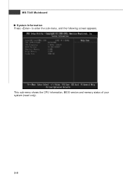
This sub-menu shows the CPU information, BIOS version and memory status of your system (read only). 3-8 MS-7345 Mainboard System Information Press to enter the sub-menu, and the following screen appears.
This sub-menu shows the CPU information, BIOS version and memory status of your system (read only). 3-8 MS-7345 Mainboard System Information Press to enter the sub-menu, and the following screen appears.
User Guide
Page 47
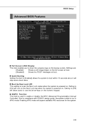
... used to compliance with PC2001 design guide, the system is powered on. Due to enable or disable the APIC (Advanced Programmable Interrupt Controller). Advanced BIOS Features BIOS Setup Full Screen LOGO Display This item enables you to use the arrow keys on the numeric keypad. IOAPIC Function This field is powered on...
... used to compliance with PC2001 design guide, the system is powered on. Due to enable or disable the APIC (Advanced Programmable Interrupt Controller). Advanced BIOS Features BIOS Setup Full Screen LOGO Display This item enables you to use the arrow keys on the numeric keypad. IOAPIC Function This field is powered on...
User Guide
Page 49
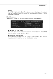
... Device The items allow you with the means to get to it , and will provide you to set the first/ second/ third boot device where BIOS attempts to boot from other device. if the system fails to load the disk operating system. You can to boot from the 1st/ 2nd/ 3rd... boot device. 3-11 Boot From Other Device Setting the option to [Yes] allows the system to try to enable it via the various ACPI methods. BIOS Setup HPET The HPET (High Precision Event Timers) is a component that is part of the chipset.
... Device The items allow you with the means to get to it , and will provide you to set the first/ second/ third boot device where BIOS attempts to boot from other device. if the system fails to load the disk operating system. You can to boot from the 1st/ 2nd/ 3rd... boot device. 3-11 Boot From Other Device Setting the option to [Yes] allows the system to try to enable it via the various ACPI methods. BIOS Setup HPET The HPET (High Precision Event Timers) is a component that is part of the chipset.
User Guide
Page 51
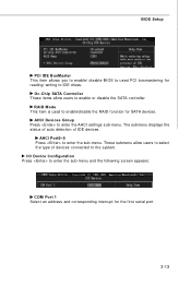
... IDE BusMaster This item allows you to enable/ disable BIOS to used to enable/disable the RAID function for reading/ writing to IDE drives. RAID Mode This item is used PCI busmastering for SATA devices. ...
... IDE BusMaster This item allows you to enable/ disable BIOS to used to enable/disable the RAID function for reading/ writing to IDE drives. RAID Mode This item is used PCI busmastering for SATA devices. ...
User Guide
Page 52
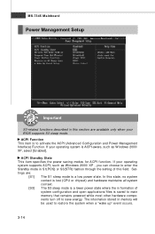
... while most other hardware components turn off to save energy. ACPI Standby State This item specifies the power saving modes for ACPI function. If your BIOS supports S3 sleep mode. Settings are available only when your operating system is a low power state.
... while most other hardware components turn off to save energy. ACPI Standby State This item specifies the power saving modes for ACPI function. If your BIOS supports S3 sleep mode. Settings are available only when your operating system is a low power state.
User Guide
Page 53
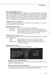
...-Call VGA BIOS From S3 W hen ACPI Standby State is set to [S3], users can select the options in this field, all devices except CPU will be awakened ... detected for more than four seconds, the computer is detected. 3-15 Settings are : [Off] Always leaves the computer in the power off . Selecting [Yes] allows BIOS to call VGABIOS to initialize the VGA card. Restore On AC Power Loss This item specifies whether your system will be shut off state. [On...
...-Call VGA BIOS From S3 W hen ACPI Standby State is set to [S3], users can select the options in this field, all devices except CPU will be awakened ... detected for more than four seconds, the computer is detected. 3-15 Settings are : [Off] Always leaves the computer in the power off . Selecting [Yes] allows BIOS to call VGABIOS to initialize the VGA card. Restore On AC Power Loss This item specifies whether your system will be shut off state. [On...


