User Guide
Page 8
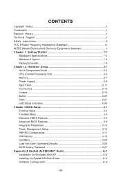
...2-2 Memory ...2-7 Power Supply ...2-8 Back Panel ...2-11 Connectors ...2-12 Jumper ...2-19 Button ...2-20 Slots ...2-21 LED Status Indicators 2-23 Chapter 3 BIOS Setup 3-1 Entering Setup ...3-2 The Main Menu ...3-4 Standard CMOS Features 3-6 Advanced BIOS Features 3-9 Integrated Peripherals 3-12 Power Management Setup 3-14 PNP/PCI Configurations 3-17 H/W Monitor ...3-19 Cell Menu ...3-20 Load Fail-Safe/ Optimized Defaults 3-26 BIOS Setting Password 3-27 Appendix A Realtek ALC888/888T Audio A-1 Installation for W indows 2000/XP A-2 Installing the Realtek HD Audio Driver A-2 Software...
...2-2 Memory ...2-7 Power Supply ...2-8 Back Panel ...2-11 Connectors ...2-12 Jumper ...2-19 Button ...2-20 Slots ...2-21 LED Status Indicators 2-23 Chapter 3 BIOS Setup 3-1 Entering Setup ...3-2 The Main Menu ...3-4 Standard CMOS Features 3-6 Advanced BIOS Features 3-9 Integrated Peripherals 3-12 Power Management Setup 3-14 PNP/PCI Configurations 3-17 H/W Monitor ...3-19 Cell Menu ...3-20 Load Fail-Safe/ Optimized Defaults 3-26 BIOS Setting Password 3-27 Appendix A Realtek ALC888/888T Audio A-1 Installation for W indows 2000/XP A-2 Installing the Realtek HD Audio Driver A-2 Software...
User Guide
Page 11
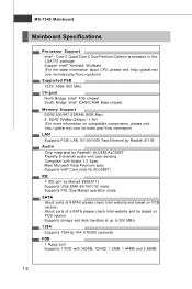
...://global.msi. Supports VoIP Card (only for ALC888T) IDE - 1 IDE port by Realtek 8111B Audio - Intel® Core 2 Quad/Core 2 Duo/Pentium/Celeron processors in the LGA775 package - c om . Supports 1394 by Realtek® ALC888/ALC888T - Chip integrated by VIA VT6308 (optional) FDD - 1 floppy port - MS-7345 Mainboard Mainboard Specifications Processor Support - Flexible 8-channel audio with jack sensing - DDR2 800/667 SDRAM (8GB Max) - 4 DDR2 DIMMs (240pin / 1.8V) (For more information on PCB version. - Supports storage...
...://global.msi. Supports VoIP Card (only for ALC888T) IDE - 1 IDE port by Realtek 8111B Audio - Intel® Core 2 Quad/Core 2 Duo/Pentium/Celeron processors in the LGA775 package - c om . Supports 1394 by Realtek® ALC888/ALC888T - Chip integrated by VIA VT6308 (optional) FDD - 1 floppy port - MS-7345 Mainboard Mainboard Specifications Processor Support - Flexible 8-channel audio with jack sensing - DDR2 800/667 SDRAM (8GB Max) - 4 DDR2 DIMMs (240pin / 1.8V) (For more information on PCB version. - Supports storage...
User Guide
Page 12
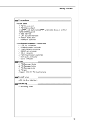
.../ 5V PCI bus Interface Form Factor - ATX (30.5cm X 24.5cm) Mounting - 9 mounting holes 1-3 Getting Started Connectors Back panel - 1 PS/2 mouse port - 1 PS/2 keyboard port - 2 eSATA ports (optional) (eSATA functionality depends on Intel ICH9/ICH9R support) - 6 USB 2.0 Ports - 1 LAN jack (10/100/1000) - 6 flexible audio jacks - 1 1394 port (optional) On-Board Pinheaders / Connectors - 3 USB 2.0 pinheaders - 1 1394 pinheader (optional) - 1 chasis intrusion connector - 1 SPDIF-out pinheader - 1 CD-in connector - 2 HW OC pinheaders (optional) - 1 front audio pinheader - 1 serial pinheader Slots...
.../ 5V PCI bus Interface Form Factor - ATX (30.5cm X 24.5cm) Mounting - 9 mounting holes 1-3 Getting Started Connectors Back panel - 1 PS/2 mouse port - 1 PS/2 keyboard port - 2 eSATA ports (optional) (eSATA functionality depends on Intel ICH9/ICH9R support) - 6 USB 2.0 Ports - 1 LAN jack (10/100/1000) - 6 flexible audio jacks - 1 1394 port (optional) On-Board Pinheaders / Connectors - 3 USB 2.0 pinheaders - 1 1394 pinheader (optional) - 1 chasis intrusion connector - 1 SPDIF-out pinheader - 1 CD-in connector - 2 HW OC pinheaders (optional) - 1 front audio pinheader - 1 serial pinheader Slots...

User Guide
Page 23
... and the pins are connected to proper ATX power supplies to ensure stable operation of the power supply is highly recommended for system stability. 3. If the POWER1 connector too closes the heatpipe and plug inconveniently. To connect the ATX 24-pin power supply, make sure the plug of the mainboard. 2. And the JPW R1 12V power connector is used to provide power to the PCIEX16 graphics card. 5 Pin Definition 1 PIN SIGNAL PIN SIGNAL Pin Definition 1 PIN SIGNAL 8 4 POWER1...
... and the pins are connected to proper ATX power supplies to ensure stable operation of the power supply is highly recommended for system stability. 3. If the POWER1 connector too closes the heatpipe and plug inconveniently. To connect the ATX 24-pin power supply, make sure the plug of the mainboard. 2. And the JPW R1 12V power connector is used to provide power to the PCIEX16 graphics card. 5 Pin Definition 1 PIN SIGNAL PIN SIGNAL Pin Definition 1 PIN SIGNAL 8 4 POWER1...
User Guide
Page 26
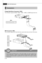
IDE1 Important If you install two IDE devices on the same cable, you must configure the drives separately to IDE device's documentation supplied by setting jumpers. Refer to master / slave mode by the vendors for jumper setting instructions. 2-12 MS-7345 Mainboard Connectors Floppy Disk Drive Connector: FDD1 This connector supports 360KB, 720KB, 1.2MB, 1.44MB or 2.88MB floppy disk drive. FDD1 IDE Connector: IDE1 This connector supports IDE hard disk drives, optical disk drives and other IDE devices.
IDE1 Important If you install two IDE devices on the same cable, you must configure the drives separately to IDE device's documentation supplied by setting jumpers. Refer to master / slave mode by the vendors for jumper setting instructions. 2-12 MS-7345 Mainboard Connectors Floppy Disk Drive Connector: FDD1 This connector supports 360KB, 720KB, 1.2MB, 1.44MB or 2.88MB floppy disk drive. FDD1 IDE Connector: IDE1 This connector supports IDE hard disk drives, optical disk drives and other IDE devices.
User Guide
Page 28
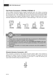
... clear the warning, you must enter the BIOS utility and clear the record. CINTRU GND 2-14 2 1 JCI1 If the mainboard has a System Hardware Monitor chipset on the screen. If the chassis is Ground and should be activated. MS-7345 Mainboard Fan Power Connectors: CPUFAN, SYSFAN1~5 The fan power connectors support system cooling fan with speed sensor to take advantage of the CPU fan control. Fan cooler set with 3 or 4 pins power connector are both available for proper CPU cooling fan. 2. CONTROL...
... clear the warning, you must enter the BIOS utility and clear the record. CINTRU GND 2-14 2 1 JCI1 If the mainboard has a System Hardware Monitor chipset on the screen. If the chassis is Ground and should be activated. MS-7345 Mainboard Fan Power Connectors: CPUFAN, SYSFAN1~5 The fan power connectors support system cooling fan with speed sensor to take advantage of the CPU fan control. Fan cooler set with 3 or 4 pins power connector are both available for proper CPU cooling fan. 2. CONTROL...
User Guide
Page 33
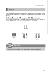
Follow the instructions below to set the FSB. 1 JB1 JB2 1 3 200 MHz 1 3 266 MHz 1 3 333 MHz Important Make sure that you to set the computer's function. Hardware Overclock FSB Jumpers: JB1, JB2 (optional) You can overclock the FSB to change your motherboard's function through the use of jumper. This section will explain how to increase the processor frequency by changing the jumpers JB1 and JB2. Hardware Setup Jumper The motherboard provides the following jumper for you power off the system before changing the jumpers 2-19
Follow the instructions below to set the FSB. 1 JB1 JB2 1 3 200 MHz 1 3 266 MHz 1 3 333 MHz Important Make sure that you to set the computer's function. Hardware Overclock FSB Jumpers: JB1, JB2 (optional) You can overclock the FSB to change your motherboard's function through the use of jumper. This section will explain how to increase the processor frequency by changing the jumpers JB1 and JB2. Hardware Setup Jumper The motherboard provides the following jumper for you power off the system before changing the jumpers 2-19
User Guide
Page 34
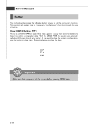
Clear CMOS Button: SW1 There is turned on board that you power off the system before clearing CMOS data. 2-20 If you to set the computer's function. With the CMOS RAM, the system can automatically boot OS every time it is a CMOS RAM on . SW1 Important Make sure that has a power supply from external battery to keep the system configuration data. Press the button to clear data. MS-7345 Mainboard Button The motherboard provides...
Clear CMOS Button: SW1 There is turned on board that you power off the system before clearing CMOS data. 2-20 If you to set the computer's function. With the CMOS RAM, the system can automatically boot OS every time it is a CMOS RAM on . SW1 Important Make sure that has a power supply from external battery to keep the system configuration data. Press the button to clear data. MS-7345 Mainboard Button The motherboard provides...
User Guide
Page 36
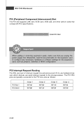
... Mainboard PCI (Peripheral Component Interconnect) Slot The PCI slot supports LAN card, SCSI card, USB card, and other add-on cards that comply with PCI specifications. 32-bit PCI Slot Important When adding or removing expansion cards, make sure that you unplug the power supply first. PCI Interrupt Request Routing The IRQ, acronym of interrupt request line and pronounced I-R-Q, are typically connected to configure any necessary hardware or software settings for the expansion card, such as follows: PCI Slot 1 PCI Slot...
... Mainboard PCI (Peripheral Component Interconnect) Slot The PCI slot supports LAN card, SCSI card, USB card, and other add-on cards that comply with PCI specifications. 32-bit PCI Slot Important When adding or removing expansion cards, make sure that you unplug the power supply first. PCI Interrupt Request Routing The IRQ, acronym of interrupt request line and pronounced I-R-Q, are typically connected to configure any necessary hardware or software settings for the expansion card, such as follows: PCI Slot 1 PCI Slot...
User Guide
Page 45
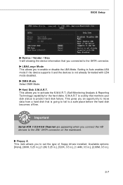
... a safe place before the hard disk becomes offline. BIOS Setup Device / Vender / Size It will showing the device information that you connected to Auto enables LBA mode if the device supports it and the devices is going to fail to predict hard disk failure. Important Serial-ATA 1/2/3/4/5/6 Channel are appearing when you to the IDE/ SATA connector on the mainboard. This allows you connect the HD devices to activate the S.M.A.R.T. (Self-Monitoring Analysis & Reporting Technology) capability for the hard disks. Floppy...
... a safe place before the hard disk becomes offline. BIOS Setup Device / Vender / Size It will showing the device information that you connected to Auto enables LBA mode if the device supports it and the devices is going to fail to predict hard disk failure. Important Serial-ATA 1/2/3/4/5/6 Channel are appearing when you to the IDE/ SATA connector on the mainboard. This allows you connect the HD devices to activate the S.M.A.R.T. (Self-Monitoring Analysis & Reporting Technology) capability for the hard disks. Floppy...
User Guide
Page 50
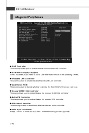
...-7345 Mainboard Integrated Peripherals USB Controller This setting allows you to enter the sub-menu and the following screen appears: 3-12 On-Chip ATA Devices Press to enable/disable the onboard USB controller. LAN Option ROM This item is used to enable/disable the onboard LAN controller. HD Audio Controller This setting is used to enable/disable the onboard audio controller. USB Device Legacy Support Select [Enabled] if you need to enable/disable the onboard IEEE1394 controller. Onboard IEEE1394 Controller This item allows you to invoke the Boot ROM of the LAN controller...
...-7345 Mainboard Integrated Peripherals USB Controller This setting allows you to enter the sub-menu and the following screen appears: 3-12 On-Chip ATA Devices Press to enable/disable the onboard USB controller. LAN Option ROM This item is used to enable/disable the onboard LAN controller. HD Audio Controller This setting is used to enable/disable the onboard audio controller. USB Device Legacy Support Select [Enabled] if you need to enable/disable the onboard IEEE1394 controller. Onboard IEEE1394 Controller This item allows you to invoke the Boot ROM of the LAN controller...
User Guide
Page 51
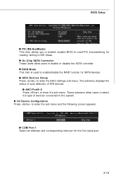
The submenu displays the status of auto detection of devices connected to enable or disable the SATA controller. BIOS Setup PCI IDE BusMaster This item allows you to enable/ disable BIOS to used to enable/disable the RAID function for SATA devices. I/O Device Configuration Press to enter the sub-menu and the following screen appears: COM Port 1 Select an address and corresponding interrupt for reading/ writing to IDE drives. RAID Mode This item is used PCI busmastering for the first serial port. 3-13 AHCI Devices Group Press to...
The submenu displays the status of auto detection of devices connected to enable or disable the SATA controller. BIOS Setup PCI IDE BusMaster This item allows you to enable/ disable BIOS to used to enable/disable the RAID function for SATA devices. I/O Device Configuration Press to enter the sub-menu and the following screen appears: COM Port 1 Select an address and corresponding interrupt for reading/ writing to IDE drives. RAID Mode This item is used PCI busmastering for the first serial port. 3-13 AHCI Devices Group Press to...
User Guide
Page 55
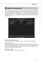
... setting specifies which graphics card is a system which allows I/O devices to the default settings. PCI Latency Timer This item controls how long each PCI slot. 3-17 PCI Slot 1/ 2 IRQ These items specify the IRQ line for each PCI device can conduct transactions for a longer time and thus improve the effective PCI bandwidth. For better PCI performance, you should make any changes to operate at speeds nearing the speed the CPU itself uses...
... setting specifies which graphics card is a system which allows I/O devices to the default settings. PCI Latency Timer This item controls how long each PCI slot. 3-17 PCI Slot 1/ 2 IRQ These items specify the IRQ line for each PCI device can conduct transactions for a longer time and thus improve the effective PCI bandwidth. For better PCI performance, you should make any changes to operate at speeds nearing the speed the CPU itself uses...
User Guide
Page 57
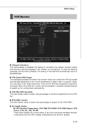
CPU Smart FAN Target The mainboard provides the Smart Fan function which can select a fan target value here. CPU Min.FAN speed(%) This item allows users to speed up for the CPU f an . PC Health Status CPU/ System Temperature, CPU FAN/ SYS FAN1/ SYS FAN2 Speed, CPU Vcore, 3.3V, 5V, 12V, 5V SB These items display the current status of all fans' speeds. 3-19 H/W Monitor BIOS Setup Chassis Intrusion The field enables or disables the feature of the monitored hardware...
CPU Smart FAN Target The mainboard provides the Smart Fan function which can select a fan target value here. CPU Min.FAN speed(%) This item allows users to speed up for the CPU f an . PC Health Status CPU/ System Temperature, CPU FAN/ SYS FAN1/ SYS FAN2 Speed, CPU Vcore, 3.3V, 5V, 12V, 5V SB These items display the current status of all fans' speeds. 3-19 H/W Monitor BIOS Setup Chassis Intrusion The field enables or disables the feature of the monitored hardware...
User Guide
Page 59
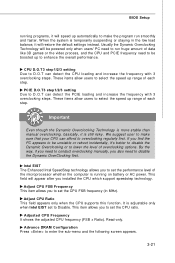
... Dynamic Overclocking Technology will speed up to overclocking regularly first. We suggest user to make the program run huge amount of overclocking options. Adjust CPU Ratio This field appears only when the CPU supports this function. CPU D.O.T3 step1/2/3 setting Due to Disable. This field will restore the default settings instead. This item allows you also need to conduct overclocking manually, you to set to D.O.T can detect the PCIE loading...
... Dynamic Overclocking Technology will speed up to overclocking regularly first. We suggest user to make the program run huge amount of overclocking options. Adjust CPU Ratio This field appears only when the CPU supports this function. CPU D.O.T3 step1/2/3 setting Due to Disable. This field will restore the default settings instead. This item allows you also need to conduct overclocking manually, you to set to D.O.T can detect the PCIE loading...
User Guide
Page 61
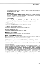
... active-to Enabled for optimal system stability and performance. Adjusted DDR M emory Frequency It shows the adjusted DDR Memory frequency. Auto Disable DIMM/PCI Frequency W hen set to -active delay of CPU, Memory, FSB and chipset. CPU Voltage / Momory Voltage / VTT FSB Voltage / NB Voltage / SB I /O gating to [Disabled], the field is adjustable. BIOS Setup start of a column-read command starts. Time interval between a read and a precharge command. DRAM TRTP W hen the Configuration DRAM Timing...
... active-to Enabled for optimal system stability and performance. Adjusted DDR M emory Frequency It shows the adjusted DDR Memory frequency. Auto Disable DIMM/PCI Frequency W hen set to -active delay of CPU, Memory, FSB and chipset. CPU Voltage / Momory Voltage / VTT FSB Voltage / NB Voltage / SB I /O gating to [Disabled], the field is adjustable. BIOS Setup start of a column-read command starts. Time interval between a read and a precharge command. DRAM TRTP W hen the Configuration DRAM Timing...
User Guide
Page 67
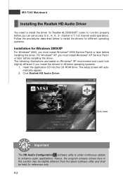
... install the drivers for different operating systems. Installation for Realtek ALC888/888T codec to function properly before you can get access to 2-, 4-, 6-, 8- Click here Important The HD Audio Configuration software utility is under continuous update to enhance audio applications. MS-7345 Mainboard Installing the Realtek HD Audio Driver You need to install the driver for Windows 2000/XP For W indows® 2000, you must install W indows® XP Service...
... install the drivers for different operating systems. Installation for Realtek ALC888/888T codec to function properly before you can get access to 2-, 4-, 6-, 8- Click here Important The HD Audio Configuration software utility is under continuous update to enhance audio applications. MS-7345 Mainboard Installing the Realtek HD Audio Driver You need to install the driver for Windows 2000/XP For W indows® 2000, you must install W indows® XP Service...
User Guide
Page 90
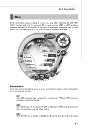
... temperature, GPU clock and memory clock of graphics card will show below . VGA Click VGA button to read current CPU temperature, FSB and CPU clock of mainboard will show below . Dual Core Center Main Before using this utility, we have to remind you install a graphics card of other brand, only hardware status of the MSI mainboard would be available. Introduction: Click each button appearing above to enter sub-menu to make further configuration or to enable or disable the Dynamic Overclocking Technology...
... temperature, GPU clock and memory clock of graphics card will show below . VGA Click VGA button to read current CPU temperature, FSB and CPU clock of mainboard will show below . Dual Core Center Main Before using this utility, we have to remind you install a graphics card of other brand, only hardware status of the MSI mainboard would be available. Introduction: Click each button appearing above to enter sub-menu to make further configuration or to enable or disable the Dynamic Overclocking Technology...
User Guide
Page 101
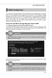
... Manager Option ROM is only available with a supported Intel chipset. Creating, Deleting and Resetting RAID Volumes: The Serial ATA RAID volume may be different from your OS. C-3 Please use + keys to enter the "Intel(R) RAID for a few seconds: Important The "Driver Model", "Serial #" and "Size" in the following procedure is the Intel RAID implementation and provides BIOS and DOS disk services. It should be integrated with the system BIOS on all motherboards...
... Manager Option ROM is only available with a supported Intel chipset. Creating, Deleting and Resetting RAID Volumes: The Serial ATA RAID volume may be different from your OS. C-3 Please use + keys to enter the "Intel(R) RAID for a few seconds: Important The "Driver Model", "Serial #" and "Size" in the following procedure is the Intel RAID implementation and provides BIOS and DOS disk services. It should be integrated with the system BIOS on all motherboards...
User Guide
Page 107
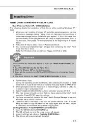
... of the drivers while installing W indows XP / 2000. 1. W indows setup will appear. 3. W hen you start installing Windows XP and older operating systems, you can use Floppy, CD/DVD or USB. You have selected the Intel® RAID controller. Intel ICH9R SATA RAID Installing Driver Install Driver in Windows Vista / XP / 2000 † New Windows Vista / XP / 2000 Installation The following details the installation of W indows setup. 2. Insert the MSI CD into the CD-ROM drive. 2. For...
... of the drivers while installing W indows XP / 2000. 1. W indows setup will appear. 3. W hen you start installing Windows XP and older operating systems, you can use Floppy, CD/DVD or USB. You have selected the Intel® RAID controller. Intel ICH9R SATA RAID Installing Driver Install Driver in Windows Vista / XP / 2000 † New Windows Vista / XP / 2000 Installation The following details the installation of W indows setup. 2. Insert the MSI CD into the CD-ROM drive. 2. For...

