
User Guide
Page 2
...the preparation of this document is the intellectual property of Phoenix Technologies Ltd. func=faqIndex Contact our technical staff at: http://support.msi.com.tw/ ii AMD, Athlon™, Athlon™ XP, Thoroughbred™, and Duron™ are registered trademarks of their respective...without notice. Alternatively, please try the following help resources for FAQ, technical guide, BIOS updates, driver updates, and other countries. Revision History Revision V1.2 Revision History First release for P35 Neo2 Date June 2007 Technical Support If a problem arises with your system and no...
...the preparation of this document is the intellectual property of Phoenix Technologies Ltd. func=faqIndex Contact our technical staff at: http://support.msi.com.tw/ ii AMD, Athlon™, Athlon™ XP, Thoroughbred™, and Duron™ are registered trademarks of their respective...without notice. Alternatively, please try the following help resources for FAQ, technical guide, BIOS updates, driver updates, and other countries. Revision History Revision V1.2 Revision History First release for P35 Neo2 Date June 2007 Technical Support If a problem arises with your system and no...

User Guide
Page 8
... ...En-2 Central Processing Unit: CPU En-5 Memory ...En-7 Connectors, Jumpers, Slots En-9 Back Panel ...En-18 LED Status Indicators En-21 BIOS Setup ...En-23 Software Information En-27 Deutsch ...De-1 Spezifikationen De-2 Hauptprozessor: CPU De-5 Speicher ...De-7 Anschlüsse, Steckbrücken... und Slots De-9 Hinteres Anschlusspaneel De-18 LED Statusdikatoren De-21 BIOS Setup ...De-23 Software-Information De-27 Français ...Fr-1 Spécificités ...Fr-2 Central Processing Unit: CPU Fr-5 ...
... ...En-2 Central Processing Unit: CPU En-5 Memory ...En-7 Connectors, Jumpers, Slots En-9 Back Panel ...En-18 LED Status Indicators En-21 BIOS Setup ...En-23 Software Information En-27 Deutsch ...De-1 Spezifikationen De-2 Hauptprozessor: CPU De-5 Speicher ...De-7 Anschlüsse, Steckbrücken... und Slots De-9 Hinteres Anschlusspaneel De-18 LED Statusdikatoren De-21 BIOS Setup ...De-23 Software-Information De-27 Français ...Fr-1 Spécificités ...Fr-2 Central Processing Unit: CPU Fr-5 ...

User Guide
Page 14
... the socket. The pins of the CPU base. Note that the clip-ends are m atched. 7. En-6 Open the load lever. 5. Push down the CPU in BIOS. 2. Cover the load plate onto the package. 9. Be sure to confirm that the alignment keys are correctly inserted. If not, take out the CPU with...
... the socket. The pins of the CPU base. Note that the clip-ends are m atched. 7. En-6 Open the load lever. 5. Push down the CPU in BIOS. 2. Cover the load plate onto the package. 9. Be sure to confirm that the alignment keys are correctly inserted. If not, take out the CPU with...

User Guide
Page 20
... Intrusion Connector This connector connects to set the FSB. 1 JB1 JB2 1 3 200 MHz 1 3 266 MHz 1 3 333 MHz Important Make sure that you must enter the BIOS utility and clear the record. 1 CINTRU 2 GND En-12 The system will be activated. MS-7345 Mainboard 13 Hardware Overclock FSB Jumpers: JB1, JB2 (optional...
... Intrusion Connector This connector connects to set the FSB. 1 JB1 JB2 1 3 200 MHz 1 3 266 MHz 1 3 333 MHz Important Make sure that you must enter the BIOS utility and clear the record. 1 CINTRU 2 GND En-12 The system will be activated. MS-7345 Mainboard 13 Hardware Overclock FSB Jumpers: JB1, JB2 (optional...

User Guide
Page 21
... connector is compliant with Intel® Front Panel I/O Connectivity Design Guide. En-13 You can attach a serial device. You must configure the setting through the BIOS setup to the VoIP card. English 16 Infrared Module Connector This connector allows you to attach an optional TV-Out bracket that sends/receives 16...
... connector is compliant with Intel® Front Panel I/O Connectivity Design Guide. En-13 You can attach a serial device. You must configure the setting through the BIOS setup to the VoIP card. English 16 Infrared Module Connector This connector allows you to attach an optional TV-Out bracket that sends/receives 16...

User Guide
Page 22
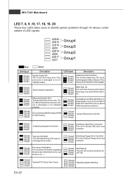
... Testing Base and Extended Memory 2 Testing base memory from 240K to 4 640K and extended memory above 1MB using various patterns. 1 3 2 Decompressing BIOS image to RAM 1 4 for you to connect to the D-Bracket™2 which integrates four LEDs and USB ports. Then, detect and initializethe video... adapter. 1 2 EarlyChipset Initialization 3 4 BIOS Sign On 1 2 This will hang if the memory mod4 ule is damaged or not in- 3 stalled properly. It allows users to identify...
... Testing Base and Extended Memory 2 Testing base memory from 240K to 4 640K and extended memory above 1MB using various patterns. 1 3 2 Decompressing BIOS image to RAM 1 4 for you to connect to the D-Bracket™2 which integrates four LEDs and USB ports. Then, detect and initializethe video... adapter. 1 2 EarlyChipset Initialization 3 4 BIOS Sign On 1 2 This will hang if the memory mod4 ule is damaged or not in- 3 stalled properly. It allows users to identify...

User Guide
Page 25
... a 66MHz, 32-bit channel for the graphics controller to configure any necessary hardware or software settings for the expansion card, such as jumpers, switches or BIOS configuration. Meanwhile, read the documentation for the throughput demands of 3D graphics. The PCI Express x 1 supports up to 250 MB/s transfer rate. AGP is an...
... a 66MHz, 32-bit channel for the graphics controller to configure any necessary hardware or software settings for the expansion card, such as jumpers, switches or BIOS configuration. Meanwhile, read the documentation for the throughput demands of 3D graphics. The PCI Express x 1 supports up to 250 MB/s transfer rate. AGP is an...
User Guide
Page 30
...Testing onboard memory size. Group4 Group3 Group2 Group1 Initializing Keyboard Controller. Group4 Group3 Group2 Group1 Decompressing BIOS image to all ISA. Group4 Group3 Group2 Group1 BIOS Sign On This will start showing information about logo, processor brand name, etc... Group4 Group3 ...fast booting. Group4 Group3 Group2 Group1 BootAttempt This will initialize IDE drive and controller. Group4 Group3 Group2 Group1 Testing VGA BIOS This will start writing VGA sign-on message to the screen. Group4 Group3 Group2 Group1 Processor Initialization This will show ...
...Testing onboard memory size. Group4 Group3 Group2 Group1 Initializing Keyboard Controller. Group4 Group3 Group2 Group1 Decompressing BIOS image to all ISA. Group4 Group3 Group2 Group1 BIOS Sign On This will start showing information about logo, processor brand name, etc... Group4 Group3 ...fast booting. Group4 Group3 Group2 Group1 BootAttempt This will initialize IDE drive and controller. Group4 Group3 Group2 Group1 Testing VGA BIOS This will start writing VGA sign-on message to the screen. Group4 Group3 Group2 Group1 Processor Initialization This will show ...

User Guide
Page 31
...chapter provides basic information on the screen during the system booting up , the 1st line appearing after the memory count is usually in this BIOS was released. Important 1.The items under continuous update for reference only. 2.Upon boot-up , and requests you to the date this chapter... are under each BIOS category described in the format: A7345IMS V1.0 011507 where: 1st digit refers to BIOS maker as A = AMI, W = AWARD, and P = PHOENIX. 2nd - 5th digit refers to the model ...
...chapter provides basic information on the screen during the system booting up , the 1st line appearing after the memory count is usually in this BIOS was released. Important 1.The items under continuous update for reference only. 2.Upon boot-up , and requests you to the date this chapter... are under each BIOS category described in the format: A7345IMS V1.0 011507 where: 1st digit refers to BIOS maker as A = AMI, W = AWARD, and P = PHOENIX. 2nd - 5th digit refers to the model ...

User Guide
Page 32
... Setup, restart the system by simultaneously pressing , , and keys. The on-line description of the highlighted setup function is the Main Menu. General Help The BIOS setup program provides a General Help screen. If you can use control keys (↑↓ ) to highlight the field and press to call up the sub...
... Setup, restart the system by simultaneously pressing , , and keys. The on-line description of the highlighted setup function is the Main Menu. General Help The BIOS setup program provides a General Help screen. If you can use control keys (↑↓ ) to highlight the field and press to call up the sub...

User Guide
Page 33
.... Save & Exit Setup Save changes to accept or enter the sub-menu. PNP/PCI Configurations This entry appears if your PC health status. Advanced BIOS Features Use this menu to specify your settings for fequency/voltage control and overclocking. The Main Menu allows you enter AMI® or AW ARD...® BIOS CMOS Setup Utility, the Main Menu will appear on the screen. Load Fail-Safe Defaults Use this menu to specify your settings for power management...
.... Save & Exit Setup Save changes to accept or enter the sub-menu. PNP/PCI Configurations This entry appears if your PC health status. Advanced BIOS Features Use this menu to specify your settings for fequency/voltage control and overclocking. The Main Menu allows you enter AMI® or AW ARD...® BIOS CMOS Setup Utility, the Main Menu will appear on the screen. Load Fail-Safe Defaults Use this menu to specify your settings for power management...

User Guide
Page 34
...] to load the default settings for optimal system performance. 2. Setup Date/ Time : Select the Standard CMOS Features and press to save the configurations and exit BIOS Setup utility. Adjust the Date, Tim e fields. 3. Important The configuration above are for general use . 1. If you need the detailed settings of...
...] to load the default settings for optimal system performance. 2. Setup Date/ Time : Select the Standard CMOS Features and press to save the configurations and exit BIOS Setup utility. Adjust the Date, Tim e fields. 3. Important The configuration above are for general use . 1. If you need the detailed settings of...

User Guide
Page 35
...-run, sim ply click the driver or utiltiy and follow the pop-up screen to activate the device. Important Please visit the MSI website to get the latest drivers and BIOS for better system performance. En-27 The Driver menu shows the available drivers. The Driver/Utility CD contains the: Driver menu...
...-run, sim ply click the driver or utiltiy and follow the pop-up screen to activate the device. Important Please visit the MSI website to get the latest drivers and BIOS for better system performance. En-27 The Driver menu shows the available drivers. The Driver/Utility CD contains the: Driver menu...


