
User Guide
Page 31
Enter the BIOS setup (if needed) to enter BIOS setup, and all about options. 3-1 The following pages will describe how to modify this information. This information is retained by a battery when the power is stored in the CMOS RAM. CHAPTER 3 AMI® BIOS USER’S GUIDE Chapter 3 AMI® BIOS USER GUIDE The system configuration information and chipset register information is off.
Enter the BIOS setup (if needed) to enter BIOS setup, and all about options. 3-1 The following pages will describe how to modify this information. This information is retained by a battery when the power is stored in the CMOS RAM. CHAPTER 3 AMI® BIOS USER’S GUIDE Chapter 3 AMI® BIOS USER GUIDE The system configuration information and chipset register information is off.
User Guide
Page 32
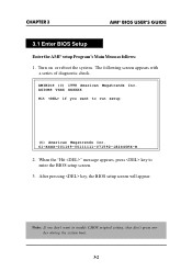
... diagnostic check. When the "Hit " message appears, press key to run setup (C) American Megatrends Inc. 61-XXXX-001169-00111111-071592-i82440FX-H 2. CHAPTER 3 AMI® BIOS USER’S GUIDE 3.1 Enter BIOS Setup Enter the AMI® setup Program's Main Menu as follows: 1. AMIBIOS (C) 1998 American Megatrends Inc.
... diagnostic check. When the "Hit " message appears, press key to run setup (C) American Megatrends Inc. 61-XXXX-001169-00111111-071592-i82440FX-H 2. CHAPTER 3 AMI® BIOS USER’S GUIDE 3.1 Enter BIOS Setup Enter the AMI® setup Program's Main Menu as follows: 1. AMIBIOS (C) 1998 American Megatrends Inc.
User Guide
Page 33
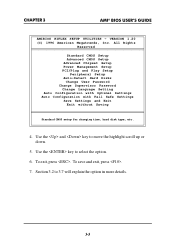
... CMOS Setup Advanced Chipset Setup Power Management Setup PCI/Plug and Play Setup Peripheral Setup Auto-Detect Hard Disks Change User Password Change Supervisor Password Change Language Setting Auto Configuration with Optimal Settings Auto Configuration with Fail Safe Settings Save Settings ...the and key to select the option. 6. Use the key to move the highlight scroll up or down. 5. CHAPTER 3 AMI® BIOS USER’S GUIDE AMIBIOS HIFLEX SETUP UTILITIES - Section 3.2 to 3.7 will explain the option in more details. 3-3 VERSION 1.20 (C) 1996 American Megatrends, Inc. To exit...
... CMOS Setup Advanced Chipset Setup Power Management Setup PCI/Plug and Play Setup Peripheral Setup Auto-Detect Hard Disks Change User Password Change Supervisor Password Change Language Setting Auto Configuration with Optimal Settings Auto Configuration with Fail Safe Settings Save Settings ...the and key to select the option. 6. Use the key to move the highlight scroll up or down. 5. CHAPTER 3 AMI® BIOS USER’S GUIDE AMIBIOS HIFLEX SETUP UTILITIES - Section 3.2 to 3.7 will explain the option in more details. 3-3 VERSION 1.20 (C) 1996 American Megatrends, Inc. To exit...

User Guide
Page 34
... to go back to modify the highlighted item. 3. Use and to choose the item and and keys to the main menu. 3-4 CHAPTER 3 AMI® BIOS USER’S GUIDE 3.2 Standard CMOS Setup 1.
... to go back to modify the highlighted item. 3. Use and to choose the item and and keys to the main menu. 3-4 CHAPTER 3 AMI® BIOS USER’S GUIDE 3.2 Standard CMOS Setup 1.
User Guide
Page 35
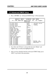
... Disabled ESC:Exit :Sel PgUp/PgDn:Modify F2/F3:Color 2. Press on "Advanced CMOS Setup" of the main menu AMIBIOS SETUP - CHAPTER 3 AMI® BIOS USER’S GUIDE 3.3 Advanced CMOS Setup 1.
... Disabled ESC:Exit :Sel PgUp/PgDn:Modify F2/F3:Color 2. Press on "Advanced CMOS Setup" of the main menu AMIBIOS SETUP - CHAPTER 3 AMI® BIOS USER’S GUIDE 3.3 Advanced CMOS Setup 1.
User Guide
Page 36
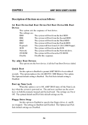
...default setting is Enabled. Network The system will boot from LS-120(120M Floppy). The setting are On or Off. CHAPTER 3 AMI® BIOS USER’S GUIDE Description of boot drives. The optimal default and Fail-Safe default settings are Disabled. 3-6 IDE1 The system will boot from the first HDD. F(... when the system is set to specify that floppy drives A: and B: are : IDE0 The system will boot from the Second HDD. The end user can then use the arrow keys on screen follows: 1st Boot Device/2nd Boot Device/3rd Boot Device/4th Boot Device This option sets the...
...default setting is Enabled. Network The system will boot from LS-120(120M Floppy). The setting are On or Off. CHAPTER 3 AMI® BIOS USER’S GUIDE Description of boot drives. The optimal default and Fail-Safe default settings are Disabled. 3-6 IDE1 The system will boot from the first HDD. F(... when the system is set to specify that floppy drives A: and B: are : IDE0 The system will boot from the Second HDD. The end user can then use the arrow keys on screen follows: 1st Boot Device/2nd Boot Device/3rd Boot Device/4th Boot Device This option sets the...
User Guide
Page 37
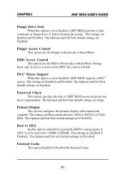
... Fail-Safe default settings are Enabled. The Optimal and Fail-Safe default settings are Disabled. The settings are Enabled and Disabled. CHAPTER 3 AMI® BIOS USER’S GUIDE Floppy Drive Seek When this option is set to Enabled, AMI® BIOS supports a PS/2® mouse. During Read-only, if you try to...
... Fail-Safe default settings are Enabled. The Optimal and Fail-Safe default settings are Disabled. The settings are Enabled and Disabled. CHAPTER 3 AMI® BIOS USER’S GUIDE Floppy Drive Seek When this option is set to Enabled, AMI® BIOS supports a PS/2® mouse. During Read-only, if you try to...

User Guide
Page 38
.... The settings are Disabled. 3-8 The settings are handled. The contents of the adaptor ROM named in the option title are ; CHAPTER 3 AMI® BIOS USER’S GUIDE System BIOS Cacheable AMI® BIOS always copies the system BIOS from ROM to RAM; C800, 16k Shadow/CC00, 16k Shadow/D000, 16K Shadow/ D400...
.... The settings are Disabled. 3-8 The settings are handled. The contents of the adaptor ROM named in the option title are ; CHAPTER 3 AMI® BIOS USER’S GUIDE System BIOS Cacheable AMI® BIOS always copies the system BIOS from ROM to RAM; C800, 16k Shadow/CC00, 16k Shadow/D000, 16K Shadow/ D400...
User Guide
Page 39
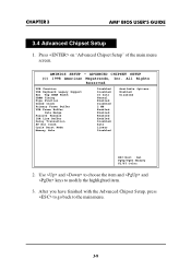
.... 3. ADVANCED CHIPSET SETUP (C) 1998 American Megatrends, Inc. Use and to choose the item and and keys to the main menu. 3-9 CHAPTER 3 AMI® BIOS USER’S GUIDE 3.4 Advanced Chipset Setup 1. Tag SRAM Width DRAM Timing Pipe Function Gated Clock Primary Frame Buffer VGA Frame Buffer Data Merge Passive Release ISA Line Buffer...
.... 3. ADVANCED CHIPSET SETUP (C) 1998 American Megatrends, Inc. Use and to choose the item and and keys to the main menu. 3-9 CHAPTER 3 AMI® BIOS USER’S GUIDE 3.4 Advanced Chipset Setup 1. Tag SRAM Width DRAM Timing Pipe Function Gated Clock Primary Frame Buffer VGA Frame Buffer Data Merge Passive Release ISA Line Buffer...
User Guide
Page 40
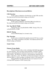
... memory to USWC memory can be buffered and combined in the processors write-combining buffer (WCB). The settings are Disabled. CHAPTER 3 AMI® BIOS USER’S GUIDE Description of the item on screen follows: USB Function Set this will enable the processor memory location C000 and DFFF segment as a special purpose outgoing...
... memory to USWC memory can be buffered and combined in the processors write-combining buffer (WCB). The settings are Disabled. CHAPTER 3 AMI® BIOS USER’S GUIDE Description of the item on screen follows: USB Function Set this will enable the processor memory location C000 and DFFF segment as a special purpose outgoing...

User Guide
Page 41
CHAPTER 3 AMI® BIOS USER’S GUIDE VGA Frame Buffer The processor provides a write-combining with buffering strategy for frame buffering. Data Merge Passive Release During Enabled, this function. 3-11 PCI cycles ...
CHAPTER 3 AMI® BIOS USER’S GUIDE VGA Frame Buffer The processor provides a write-combining with buffering strategy for frame buffering. Data Merge Passive Release During Enabled, this function. 3-11 PCI cycles ...

User Guide
Page 44
... go back to modify the highlighted item. 3. Use and to choose the item and and keys to the main menu. 3-14 CHAPTER 3 AMI® BIOS USER’S GUIDE 3.5 Power Management Setup 1.
... go back to modify the highlighted item. 3. Use and to choose the item and and keys to the main menu. 3-14 CHAPTER 3 AMI® BIOS USER’S GUIDE 3.5 Power Management Setup 1.

User Guide
Page 45
..., 3 min, 4 min, 5 min, 6 min, 7 min, 8 min, 9 min, 10 min, 11 min, 12 min, 13 min, 14 min or 15 min. CHAPTER 3 AMI® BIOS USER’S GUIDE Description of the item on screen follows: Power Management/APM Set this length of time expires, the computer enters Standby power state. The Optimal and...
..., 3 min, 4 min, 5 min, 6 min, 7 min, 8 min, 9 min, 10 min, 11 min, 12 min, 13 min, 14 min or 15 min. CHAPTER 3 AMI® BIOS USER’S GUIDE Description of the item on screen follows: Power Management/APM Set this length of time expires, the computer enters Standby power state. The Optimal and...

User Guide
Page 46
.../Off, the system will be turned off the system. Note: If you have change the setting, you push the switch. CHAPTER 3 AMI® BIOS USER’S GUIDE Suspend Time Out This option specifies the length of a period of time expires, the computer enters Suspend power state. During Enabled, the system will boot...
.../Off, the system will be turned off the system. Note: If you have change the setting, you push the switch. CHAPTER 3 AMI® BIOS USER’S GUIDE Suspend Time Out This option specifies the length of a period of time expires, the computer enters Suspend power state. During Enabled, the system will boot...

User Guide
Page 47
RTC Alarm Minute Choose which day the system will boot up. Then, power off the system. CHAPTER 3 AMI® BIOS USER’S GUIDE RTC Alarm Resume From Soft-Off This function is for setting the Date, Hour, Minute, and Second for your computer to the operating system. Note: ...
RTC Alarm Minute Choose which day the system will boot up. Then, power off the system. CHAPTER 3 AMI® BIOS USER’S GUIDE RTC Alarm Resume From Soft-Off This function is for setting the Date, Hour, Minute, and Second for your computer to the operating system. Note: ...

User Guide
Page 48
..., Inc. After you have finished with the PCI/Plug and Play Setup, press to go back to modify the highlighted item. 3. CHAPTER 3 AMI® BIOS USER’S GUIDE 3.6 PCI/Plug and Play Setup 1.
..., Inc. After you have finished with the PCI/Plug and Play Setup, press to go back to modify the highlighted item. 3. CHAPTER 3 AMI® BIOS USER’S GUIDE 3.6 PCI/Plug and Play Setup 1.

User Guide
Page 49
... the computer (one PCI and ISA) and the Bit settings are 32, 64, 96, 128, 160, 192, 224 or 248. CHAPTER 3 AMI® BIOS USER’S GUIDE Description of the item on screen follows: Plug and Play Aware O/S Set this option to Yes if the operating system in this computer is set...
... the computer (one PCI and ISA) and the Bit settings are 32, 64, 96, 128, 160, 192, 224 or 248. CHAPTER 3 AMI® BIOS USER’S GUIDE Description of the item on screen follows: Plug and Play Aware O/S Set this option to Yes if the operating system in this computer is set...
User Guide
Page 50
...-Safe default settings are Auto. 3-20 The Optimal and Fail-Safe default setting is installed), Slot1, Slot2, Slot3 or Slot4. CHAPTER 3 AMI® BIOS USER’S GUIDE Offboard PCI IDE Card This option specifies if an offboard PCI IDE controller adapter card is installed in the computer, you must specify the PCI...
...-Safe default settings are Auto. 3-20 The Optimal and Fail-Safe default setting is installed), Slot1, Slot2, Slot3 or Slot4. CHAPTER 3 AMI® BIOS USER’S GUIDE Offboard PCI IDE Card This option specifies if an offboard PCI IDE controller adapter card is installed in the computer, you must specify the PCI...

User Guide
Page 51
... allocated to it . If all IRQs are set to ISA/EISA and IRQ14 and 15 are configured as PCI/PnP. CHAPTER 3 AMI® BIOS USER’S GUIDE DMA Channel 0/1/3/5/6/7 These options specify the bus that the specified DMA channel is used on. IRQ3/IRQ4/IRQ5/RQ7/IRQ9/IRQ10/IRQ11/IRQ14/IRQ15 These... options specify the bus that the specified IRQ line is used. If more DMAs must be removed from the pool, the end user can use these...
... allocated to it . If all IRQs are set to ISA/EISA and IRQ14 and 15 are configured as PCI/PnP. CHAPTER 3 AMI® BIOS USER’S GUIDE DMA Channel 0/1/3/5/6/7 These options specify the bus that the specified DMA channel is used on. IRQ3/IRQ4/IRQ5/RQ7/IRQ9/IRQ10/IRQ11/IRQ14/IRQ15 These... options specify the bus that the specified IRQ line is used. If more DMAs must be removed from the pool, the end user can use these...

User Guide
Page 52
... Auto 3F8H 3 2F8H Normal 4 N/A N/A N/A Auto EPP N/A 7 N/A Both Available Options: Enabled Disabled ESC:Exit :Sel PgUp/PgDn:Modify F2/F3:Color 2. CHAPTER 3 AMI® BIOS USER’S GUIDE 3.7 Peripheral Setup 1. After you have finished with the Peripheral Setup, press to go back to modify the highlighted item. 3. AMIBIOS SETUP - Use and to choose...
... Auto 3F8H 3 2F8H Normal 4 N/A N/A N/A Auto EPP N/A 7 N/A Both Available Options: Enabled Disabled ESC:Exit :Sel PgUp/PgDn:Modify F2/F3:Color 2. CHAPTER 3 AMI® BIOS USER’S GUIDE 3.7 Peripheral Setup 1. After you have finished with the Peripheral Setup, press to go back to modify the highlighted item. 3. AMIBIOS SETUP - Use and to choose...


