User Guide
Page 1
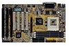
...power fan control, CPU temperature detect and protect, system voltage detect. 1-1 CHAPTER 1 INTRODUCTION Chapter 1 INTRODUCTION The ATX AL9 mainboard is a high-performance personal computer mainboard. The mainboard uses the highly integrated Aladdin® 5 chipset to support the PCI/ISA and Green standards, and to provide the... Host/AGP bridge. The mainboard also supports the Hardware Monitor Controller as ACPI (Advanced Configuration and Power Interface). The Aladdin® 5 chipset also improves ...
...power fan control, CPU temperature detect and protect, system voltage detect. 1-1 CHAPTER 1 INTRODUCTION Chapter 1 INTRODUCTION The ATX AL9 mainboard is a high-performance personal computer mainboard. The mainboard uses the highly integrated Aladdin® 5 chipset to support the PCI/ISA and Green standards, and to provide the... Host/AGP bridge. The mainboard also supports the Hardware Monitor Controller as ACPI (Advanced Configuration and Power Interface). The Aladdin® 5 chipset also improves ...
User Guide
Page 2
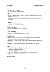
...; 6x86/6x86L/6x86MX and AMD® K5/K6 processors are supported. AGP specification compliant - l Supports 3.3v Extended Data Output (EDO) and SDRAM DIMM. CHAPTER 1 INTRODUCTION 1.1 Mainboard Features CPU l Socket 7 supports Intel® Pentium® processor/Pentium® processor with MMXTM technology. Main Memory l Supports six memory banks using three 168-pin...
...; 6x86/6x86L/6x86MX and AMD® K5/K6 processors are supported. AGP specification compliant - l Supports 3.3v Extended Data Output (EDO) and SDRAM DIMM. CHAPTER 1 INTRODUCTION 1.1 Mainboard Features CPU l Socket 7 supports Intel® Pentium® processor/Pentium® processor with MMXTM technology. Main Memory l Supports six memory banks using three 168-pin...
User Guide
Page 3
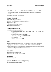
...-Board Peripherals include: - 1 floppy port supports 2 FDD with PIO, Bus Master and Ultra DMA/33 operation modes. BIOS l The mainboard BIOS provides "Plug & Play" BIOS which records your mainboard specifications. l Connect up . Dimension l Standard ATX form factor l 30cm(L) x 18.6cm(W) x 4 layer PCB Mounting l 6 mounting holes System Hardware Monitor (optional) l CPU Rotation Speed Control...
...-Board Peripherals include: - 1 floppy port supports 2 FDD with PIO, Bus Master and Ultra DMA/33 operation modes. BIOS l The mainboard BIOS provides "Plug & Play" BIOS which records your mainboard specifications. l Connect up . Dimension l Standard ATX form factor l 30cm(L) x 18.6cm(W) x 4 layer PCB Mounting l 6 mounting holes System Hardware Monitor (optional) l CPU Rotation Speed Control...
User Guide
Page 6
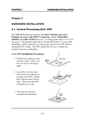
... with MMXTM technology, Cyrix® 6x86/6x86L/ 6x86MX and AMD® K5/K6 processors. CHAPTER 2 HARDWARE INSTALLATION Chapter 2 HARDWARE INSTALLATION 2.1 Central Processing Unit: CPU The ATX AL9 mainboard operates with Intel® Pentium® processor/ Pentium® processor with 2.1V to complete the installation. CPU White dot/ Cut edge 3. The...
... with MMXTM technology, Cyrix® 6x86/6x86L/ 6x86MX and AMD® K5/K6 processors. CHAPTER 2 HARDWARE INSTALLATION Chapter 2 HARDWARE INSTALLATION 2.1 Central Processing Unit: CPU The ATX AL9 mainboard operates with Intel® Pentium® processor/ Pentium® processor with 2.1V to complete the installation. CPU White dot/ Cut edge 3. The...

User Guide
Page 16
When connecting the wire to GND. If your mainboard has System Hardware Monitor chipset on-board, you can use a specially designed fan w/ speed sensor to take note that the red wire is the positive ...
When connecting the wire to GND. If your mainboard has System Hardware Monitor chipset on-board, you can use a specially designed fan w/ speed sensor to take note that the red wire is the positive ...

User Guide
Page 17
It supports six memory banks for a maximum of 768MB memory. You can use DIMM from 8MB, 16MB, 32MB, 64MB, 128MB, or 256MB. DIMM2(Bank 2) DIMM1(Bank 1) DIMM3(Bank 0) 2-12 CHAPTER 2 HARDWARE INSTALLATION 2.6 Memory Installation 2.6-1 Memory Bank Configuration The mainboard provides three 168-pin DIMM(Double In-Line Memory) sockets.
It supports six memory banks for a maximum of 768MB memory. You can use DIMM from 8MB, 16MB, 32MB, 64MB, 128MB, or 256MB. DIMM2(Bank 2) DIMM1(Bank 1) DIMM3(Bank 0) 2-12 CHAPTER 2 HARDWARE INSTALLATION 2.6 Memory Installation 2.6-1 Memory Bank Configuration The mainboard provides three 168-pin DIMM(Double In-Line Memory) sockets.

User Guide
Page 19
The DRAM addressing and the size supported by the mainboard is shown next page. 2-14 CHAPTER 2 HARDWARE INSTALLATION 2.6-3 Memory Population Rules 1. This mainboard supports Table Free memory, so memory can be installed in DIMM1, DIMM2, or DIMM 3 in any order. 2. Use only 3.3v unbuffered DIMM. 3.
The DRAM addressing and the size supported by the mainboard is shown next page. 2-14 CHAPTER 2 HARDWARE INSTALLATION 2.6-3 Memory Population Rules 1. This mainboard supports Table Free memory, so memory can be installed in DIMM1, DIMM2, or DIMM 3 in any order. 2. Use only 3.3v unbuffered DIMM. 3.

User Guide
Page 22
.../OFF. You can connect the HDD LED from the system case are used to this pin. (See Figure 2.1). 2-17 CHAPTER 2 HARDWARE INSTALLATION 2.7-1 Turbo LED This mainboard is always on . Avoid rebooting the system when the HDD LED is lit. You can connect the Power LED from the system case to this...
.../OFF. You can connect the HDD LED from the system case are used to this pin. (See Figure 2.1). 2-17 CHAPTER 2 HARDWARE INSTALLATION 2.7-1 Turbo LED This mainboard is always on . Avoid rebooting the system when the HDD LED is lit. You can connect the Power LED from the system case to this...

User Guide
Page 23
You can attach a floppy disk cable directly to this connector. FDC 1 2-18 CHAPTER 2 HARDWARE INSTALLATION 2.8 Floppy Disk Connector: FDC The mainboard also provides a standard floppy disk connector, FDC that supports 360K, 720K, 1.2M, 1.44M and 2.88M floppy disk types.
You can attach a floppy disk cable directly to this connector. FDC 1 2-18 CHAPTER 2 HARDWARE INSTALLATION 2.8 Floppy Disk Connector: FDC The mainboard also provides a standard floppy disk connector, FDC that supports 360K, 720K, 1.2M, 1.44M and 2.88M floppy disk types.

User Guide
Page 24
... for future BIOS) and other devices to IDE1. IDE1 can connect a Master and a Slave drive. 2-19 CHAPTER 2 HARDWARE INSTALLATION 2.9 Hard Disk Connectors: IDE1 & IDE2 The mainboard has a 32-bit Enhanced PCI IDE Controller that provides two HDD connectors IDE1 (Primary) and IDE2 (Secondary). Secondary IDE Connector Primary IDE Connector 1 1 IDE1(Primary...
... for future BIOS) and other devices to IDE1. IDE1 can connect a Master and a Slave drive. 2-19 CHAPTER 2 HARDWARE INSTALLATION 2.9 Hard Disk Connectors: IDE1 & IDE2 The mainboard has a 32-bit Enhanced PCI IDE Controller that provides two HDD connectors IDE1 (Primary) and IDE2 (Secondary). Secondary IDE Connector Primary IDE Connector 1 1 IDE1(Primary...

User Guide
Page 27
CHAPTER 2 HARDWARE INSTALLATION 2.12 Serial Port Connectors: COM A & COM B The mainboard has two serial ports COMA and COMB. You can attach a mouse or a modem cable directly into these connectors. 1 2 3 45 67 8 9 COM A COM B Serial Ports (9-pin ...
CHAPTER 2 HARDWARE INSTALLATION 2.12 Serial Port Connectors: COM A & COM B The mainboard has two serial ports COMA and COMB. You can attach a mouse or a modem cable directly into these connectors. 1 2 3 45 67 8 9 COM A COM B Serial Ports (9-pin ...

User Guide
Page 28
Parallel Port (25-pin Female) LPT 13 1 25 14 PIN # 1 2 3 4 5 6 7 8 9 10 11 12 13 PIN DEFINITION DEFINITION PIN # DEFINITION STROBE 14 AUTO FEED# DATA0 15 ERR# DATA1 16 INIT# DATA2 17 SLIN# DATA3 18 GND DATA4 19 GND DATA5 20 GND DATA6 21 GND DATA7 22 GND ACK# 23 GND BUSY 24 GND PE 25 GND SELECT 2-23 CHAPTER 2 HARDWARE INSTALLATION 2.13 Parallel Port Connector: LPT The mainboard provides a connector for LPT. A parallel port is a standard printer port that also supports Enhanced Parallel Port(EPP) and Extended capabilities Parallel Port(ECP).
Parallel Port (25-pin Female) LPT 13 1 25 14 PIN # 1 2 3 4 5 6 7 8 9 10 11 12 13 PIN DEFINITION DEFINITION PIN # DEFINITION STROBE 14 AUTO FEED# DATA0 15 ERR# DATA1 16 INIT# DATA2 17 SLIN# DATA3 18 GND DATA4 19 GND DATA5 20 GND DATA6 21 GND DATA7 22 GND ACK# 23 GND BUSY 24 GND PE 25 GND SELECT 2-23 CHAPTER 2 HARDWARE INSTALLATION 2.13 Parallel Port Connector: LPT The mainboard provides a connector for LPT. A parallel port is a standard printer port that also supports Enhanced Parallel Port(EPP) and Extended capabilities Parallel Port(ECP).

User Guide
Page 29
... 2 2-24 You can plug a keyboard cable directly to this connector. CHAPTER 2 HARDWARE INSTALLATION 2.14 Keyboard Connector: PSKBC Mouse Connector: PSMSC The mainboard provides a standard PS/2® keyboard mini DIN connector for attaching a PS/2® mouse. You can plug a PS/2® mouse directly into this...definition as shown below: PS/2® Mouse (6-pin Female) PS/2® Keyboard (6-pin Female) 2.15 USB Connectors: USB The mainboard provide a USB(Universal Serial Bus) connector for attaching USB devices like keyboard, mouse or etc. You can plug it directly to this connector...
... 2 2-24 You can plug a keyboard cable directly to this connector. CHAPTER 2 HARDWARE INSTALLATION 2.14 Keyboard Connector: PSKBC Mouse Connector: PSMSC The mainboard provides a standard PS/2® keyboard mini DIN connector for attaching a PS/2® mouse. You can plug a PS/2® mouse directly into this...definition as shown below: PS/2® Mouse (6-pin Female) PS/2® Keyboard (6-pin Female) 2.15 USB Connectors: USB The mainboard provide a USB(Universal Serial Bus) connector for attaching USB devices like keyboard, mouse or etc. You can plug it directly to this connector...

User Guide
Page 30
If you use the on-board battery, you must be able to clear the CMOS, There is off. Then, return to retain the mainboard configuration in CMOS RAM. CHAPTER 2 HARDWARE INSTALLATION 2.16 External Battery Connector: JP10 A battery must short 2-3 pins of JP10 to keep the CMOS data. 1 4 JP10 JP10 1 4 1 4 Function Keep Data Clear Data (Short for 10 second) Note: You can clear CMOS by shorting 3-4 pin for 10 second, while the system is always a 3V Standby power, so you need to unplug the system. 2-25 To be used to 2-3 pin position.
If you use the on-board battery, you must be able to clear the CMOS, There is off. Then, return to retain the mainboard configuration in CMOS RAM. CHAPTER 2 HARDWARE INSTALLATION 2.16 External Battery Connector: JP10 A battery must short 2-3 pins of JP10 to keep the CMOS data. 1 4 JP10 JP10 1 4 1 4 Function Keep Data Clear Data (Short for 10 second) Note: You can clear CMOS by shorting 3-4 pin for 10 second, while the system is always a 3V Standby power, so you need to unplug the system. 2-25 To be used to 2-3 pin position.
User Guide
Page 50
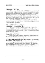
.../PCI Slot4 IRQ Priority These options specify the priority IRQ to be assigned to be used by the Primary (or Secondary) IDE channel on the mainboard where the offboard PCI IDE controller is installed in the computer, you must specify the PCI expansion slot on the offboard PCI IDE controller.
.../PCI Slot4 IRQ Priority These options specify the priority IRQ to be assigned to be used by the Primary (or Secondary) IDE channel on the mainboard where the offboard PCI IDE controller is installed in the computer, you must specify the PCI expansion slot on the offboard PCI IDE controller.


