
User Guide
Page 2
... radio frequency energy and, if not installed and used in accordance with the instruction manual, may cause undesired operation ii VOIRLANOTICED'INSTALLATIONAVANTDERACCORDERAURESEAU. Micro-Star International MS-6712 This device complies with the emission limits. Notice 2 Shielded interface cables and A.C. power cord, if any interference received, including interference that may cause harmful interference...
... radio frequency energy and, if not installed and used in accordance with the instruction manual, may cause undesired operation ii VOIRLANOTICED'INSTALLATIONAVANTDERACCORDERAURESEAU. Micro-Star International MS-6712 This device complies with the emission limits. Notice 2 Shielded interface cables and A.C. power cord, if any interference received, including interference that may cause harmful interference...

User Guide
Page 8
Designed to fit the advanced AMD® Athlon™, Athlon™ XP or Duron™ processors, the MS-6712 delivers a high performance and professional desktop platform solution. 1-1 The MS-6712 v1.X ATX mainboard is based on VIA® Apollo KT400A North Bridge & VT8235 South Bridge chipset for purchasing the MS-6712 v1.X ATX mainboard. Getting Started Getting Started Thank you for optimal system efficiency.
Designed to fit the advanced AMD® Athlon™, Athlon™ XP or Duron™ processors, the MS-6712 delivers a high performance and professional desktop platform solution. 1-1 The MS-6712 v1.X ATX mainboard is based on VIA® Apollo KT400A North Bridge & VT8235 South Bridge chipset for purchasing the MS-6712 v1.X ATX mainboard. Getting Started Getting Started Thank you for optimal system efficiency.
User Guide
Page 9
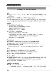
...2800+ or higher speed (For the latest information about CPU, please visit our Web site at http://www. Supports 200/266/333MHz front side bus - MS-6712 ATX Mainboard Mainboard Specifications CPU † Supports Socket A (Socket-462) for AMD® Athlon™/Athlon™ XP /Duron™ processors † ... Peripherals † On-Board Peripherals include: - 1 floppy port supports 2 FDDs with 360K, 720K, 1.2M, 1.44M and 1-2 Integrated Direct Sound AC97 audio - msi.com.tw/program/products/mainboard/mbd/pro_mbd_cpu_support.php) Chipset † VIA® KT400A North Bridge -
...2800+ or higher speed (For the latest information about CPU, please visit our Web site at http://www. Supports 200/266/333MHz front side bus - MS-6712 ATX Mainboard Mainboard Specifications CPU † Supports Socket A (Socket-462) for AMD® Athlon™/Athlon™ XP /Duron™ processors † ... Peripherals † On-Board Peripherals include: - 1 floppy port supports 2 FDDs with 360K, 720K, 1.2M, 1.44M and 1-2 Integrated Direct Sound AC97 audio - msi.com.tw/program/products/mainboard/mbd/pro_mbd_cpu_support.php) Chipset † VIA® KT400A North Bridge -

User Guide
Page 13
... - The 4 LEDs can use graphic signal display to debug the system. The D-LED will hang if the memory module is damaged or not installed properly. MS-6712 ATX Mainboard D-Bracket™ 2 (Optional) D-Bracket™ 2 is a USB bracket integrating four Diagnostic LEDs, which use the feature to detect if there are any problems or...
... - The 4 LEDs can use graphic signal display to debug the system. The D-LED will hang if the memory module is damaged or not installed properly. MS-6712 ATX Mainboard D-Bracket™ 2 (Optional) D-Bracket™ 2 is a USB bracket integrating four Diagnostic LEDs, which use the feature to detect if there are any problems or...

User Guide
Page 15
... enable 6-channel support with 6-channel audio output, you should convert it to meet increasing demands for home entertainment. MS-6712 ATX Mainboard MSI DVD 5.1 Channel (Optional) The motherboard comes with MSI DVD application which supports 5.1 channel (6-channel audio) operation. MSI DVD supports Dolby Digital format only. The accompanying MSI DVD is a convenient tool to Dolby Digital format first. 1-8
... enable 6-channel support with 6-channel audio output, you should convert it to meet increasing demands for home entertainment. MS-6712 ATX Mainboard MSI DVD 5.1 Channel (Optional) The motherboard comes with MSI DVD application which supports 5.1 channel (6-channel audio) operation. MSI DVD supports Dolby Digital format only. The accompanying MSI DVD is a convenient tool to Dolby Digital format first. 1-8
User Guide
Page 17
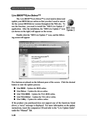
... the desired button to the "Live Update Guide" under the "Manual" Tab. 1-10 If the product you need to install the "MSI Live Update 2" application. z Live VGA BIOS - z Live Utility - MS-6712 ATX Mainboard Live BIOS™/Live Driver™ The Live BIOS™/Live Driver™ is displayed. Updates the drivers online. z Live...
... the desired button to the "Live Update Guide" under the "Manual" Tab. 1-10 If the product you need to install the "MSI Live Update 2" application. z Live VGA BIOS - z Live Utility - MS-6712 ATX Mainboard Live BIOS™/Live Driver™ The Live BIOS™/Live Driver™ is displayed. Updates the drivers online. z Live...

User Guide
Page 22
... CPU is likely to a 90degree angle. 3. If the CPU is properly and completely embedded into the socket and can only fit in the correct orientation. 4. MS-6712 ATX Mainboard CPU Installation Procedures for the gold arrow. The gold arrow should be seen.
... CPU is likely to a 90degree angle. 3. If the CPU is properly and completely embedded into the socket and can only fit in the correct orientation. 4. MS-6712 ATX Mainboard CPU Installation Procedures for the gold arrow. The gold arrow should be seen.
User Guide
Page 24
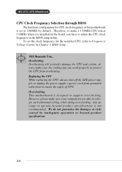
...clock frequency in Chapter 3. MSI Reminds You... Replacing the CPU While replacing the CPU, always turn off the ATX power supply or unplug the power supply's power cord from overheating. We do not guarantee the damages or risks caused by default. MS-6712 ATX Mainboard CPU Clock Frequency ...first to support overclocking. However, please make a 133MHz CPU run at 133MHz when it is designed to ensure the safety of the motherboard is not recommended. Any attempt to tolerate such abnormal setting, while doing overclocking. Therefore, to make sure your components are able ...
...clock frequency in Chapter 3. MSI Reminds You... Replacing the CPU While replacing the CPU, always turn off the ATX power supply or unplug the power supply's power cord from overheating. We do not guarantee the damages or risks caused by default. MS-6712 ATX Mainboard CPU Clock Frequency ...first to support overclocking. However, please make a 133MHz CPU run at 133MHz when it is designed to ensure the safety of the motherboard is not recommended. Any attempt to tolerate such abnormal setting, while doing overclocking. Therefore, to make sure your components are able ...

User Guide
Page 26
...the golden finger on the memory module is properly inserted in the right orientation. 2. The plastic clip at least one notch on the slots. MS-6712 ATX Mainboard DIMM Module Combination Install at each side of module. Insert the DIMM memory module vertically into the DIMM slot. The DDR DIMM has ...only one DIMM module on the center of the DIMM slot will only fit in the socket. 2-8 Volt Notch MSI Reminds You... The module will automatically close. You can barely see the golden finger if the module is deeply inserted in any combination as ...
...the golden finger on the memory module is properly inserted in the right orientation. 2. The plastic clip at least one notch on the slots. MS-6712 ATX Mainboard DIMM Module Combination Install at each side of module. Insert the DIMM memory module vertically into the DIMM slot. The DDR DIMM has ...only one DIMM module on the center of the DIMM slot will only fit in the socket. 2-8 Volt Notch MSI Reminds You... The module will automatically close. You can barely see the golden finger if the module is deeply inserted in any combination as ...

User Guide
Page 28
MS-6712 ATX Mainboard Back Panel The back panel provides the following connectors: Mouse Parallel Keyboard USB COM A COM B LAN (Optional) USB MIC L-in L-out Mouse Connector The ...
MS-6712 ATX Mainboard Back Panel The back panel provides the following connectors: Mouse Parallel Keyboard USB COM A COM B LAN (Optional) USB MIC L-in L-out Mouse Connector The ...

User Guide
Page 30
MS-6712 ATX Mainboard Parallel Port Connector: LPT1 The mainboard provides a 25-pin female centronic connector as LPT. A parallel port is a standard printer port that supports Enhanced Parallel ...
MS-6712 ATX Mainboard Parallel Port Connector: LPT1 The mainboard provides a 25-pin female centronic connector as LPT. A parallel port is a standard printer port that supports Enhanced Parallel ...

User Guide
Page 32
... Request To Send Clear To Send Ring Indicate RJ-45 LAN Jack (Optional) The mainboard provides a RJ-45 connector that send/receive 16 bytes FIFOs. MS-6712 ATX Mainboard Serial Port Connectors: COM A & COM B The mainboard offers two 9-pin male DIN connectors as serial port COM A & COM B.
... Request To Send Clear To Send Ring Indicate RJ-45 LAN Jack (Optional) The mainboard provides a RJ-45 connector that send/receive 16 bytes FIFOs. MS-6712 ATX Mainboard Serial Port Connectors: COM A & COM B The mainboard offers two 9-pin male DIN connectors as serial port COM A & COM B.

User Guide
Page 34
MSI Reminds You... IDE1 can also connect a Master and a Slave drive. If you install two hard disks on cable, you must configure second hard drive to ... connected to the hard disk documentation supplied by setting its jumper. Refer to IDE1. IDE2 (Secondary IDE Connector) IDE2 can connect a Master and a Slave drive. MS-6712 ATX Mainboard Hard Disk Connectors: IDE1 & IDE2 The mainboard has a 32-bit Enhanced PCI IDE and Ultra DMA 33/66/ 100/133 controller that provides PIO...
MSI Reminds You... IDE1 can also connect a Master and a Slave drive. If you install two hard disks on cable, you must configure second hard drive to ... connected to the hard disk documentation supplied by setting its jumper. Refer to IDE1. IDE2 (Secondary IDE Connector) IDE2 can connect a Master and a Slave drive. MS-6712 ATX Mainboard Hard Disk Connectors: IDE1 & IDE2 The mainboard has a 32-bit Enhanced PCI IDE and Ultra DMA 33/66/ 100/133 controller that provides PIO...

User Guide
Page 36
... Power Switch high reference pull-up Reset Switch high reference pull-up Power Switch low reference pull-down to the front panel switches and LEDs. MS-6712 ATX Mainboard Front Panel Connectors: JFP1 & JFP2 The mainboard provides two front panel connectors for electrical connection to GND Reserved.
... Power Switch high reference pull-up Reset Switch high reference pull-up Power Switch low reference pull-down to the front panel switches and LEDs. MS-6712 ATX Mainboard Front Panel Connectors: JFP1 & JFP2 The mainboard provides two front panel connectors for electrical connection to GND Reserved.
User Guide
Page 38
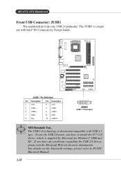
... USB 1.1 spec. JUSB1 Pin Definition Pin Description Pin Description 1 VCC 2 VCC 3 USB0- 4 USB1- 5 USB0+ 6 USB1+ 7 GND 8 GND 9 Key 10 USBOC 2 10 1 9 JUSB1 (USB 1.1/Intel spec) MSI Reminds You... MS-6712 ATX Mainboard Front USB Connector: JUSB1 The mainboard provides one USB 2.0 pinheader.
... USB 1.1 spec. JUSB1 Pin Definition Pin Description Pin Description 1 VCC 2 VCC 3 USB0- 4 USB1- 5 USB0+ 6 USB1+ 7 GND 8 GND 9 Key 10 USBOC 2 10 1 9 JUSB1 (USB 1.1/Intel spec) MSI Reminds You... MS-6712 ATX Mainboard Front USB Connector: JUSB1 The mainboard provides one USB 2.0 pinheader.

User Guide
Page 40
... for digital audio transmission (one for optical fiber connection and the other for coaxial), and 2 analog Line-Out jacks for Sony & Philips Digital Interface (SPDIF). MS-6712 ATX Mainboard S-Bracket Connector: JSP3 The connector allows you need to remove the plug from the jack first. For more information on the S-Bracket, refer to...
... for digital audio transmission (one for optical fiber connection and the other for coaxial), and 2 analog Line-Out jacks for Sony & Philips Digital Interface (SPDIF). MS-6712 ATX Mainboard S-Bracket Connector: JSP3 The connector allows you need to remove the plug from the jack first. For more information on the S-Bracket, refer to...

User Guide
Page 42
... 4 GND 5 IRTX 6 IRRX Chassis Intrusion Switch Connector: JCI1 This connector is opened, the switch will record this status and show a warning message on the screen. MS-6712 ATX Mainboard IrDA Infrared Module Header: JIR1 The connector allows you must configure the setting through the BIOS setup to IrDA Infrared module. You must enter...
... 4 GND 5 IRTX 6 IRRX Chassis Intrusion Switch Connector: JCI1 This connector is opened, the switch will record this status and show a warning message on the screen. MS-6712 ATX Mainboard IrDA Infrared Module Header: JIR1 The connector allows you must configure the setting through the BIOS setup to IrDA Infrared module. You must enter...

User Guide
Page 44
... by shorting 2-3 pin while the system is on; You can automatically boot OS every time it will explain how to change your motherboard's function through the use the JBAT1 (Clear CMOS Jumper ) to clear data. Avoid clearing the CMOS while the system is off..... it is a CMOS RAM on . Then return to clear the data: 3 3 1 Keep Data 1 Clear Data 3 1 JBAT1 MSI Reminds You... If you to set the computer's function. MS-6712 ATX Mainboard Jumpers The motherboard provides the following jumpers for you want to clear the system configuration, use of system configuration.
... by shorting 2-3 pin while the system is on; You can automatically boot OS every time it will explain how to change your motherboard's function through the use the JBAT1 (Clear CMOS Jumper ) to clear data. Avoid clearing the CMOS while the system is off..... it is a CMOS RAM on . Then return to clear the data: 3 3 1 Keep Data 1 Clear Data 3 1 JBAT1 MSI Reminds You... If you to set the computer's function. MS-6712 ATX Mainboard Jumpers The motherboard provides the following jumpers for you want to clear the system configuration, use of system configuration.

User Guide
Page 46
The PCI IRQ pins are hardware lines over which devices can send interrupt signals to the PCI bus INT A# ~ INT D# pins as follows: PCI Slot 1 PCI Slot 2 PCI Slot 3 PCI Slot 4 PCI Slot 5 PCI Slot 6 Order 1 INT A# INT B# INT C# INT D# INT B# INT C# Order 2 INT B# INT C# INT D# INT A# INT C# INT D# Order 3 INT C# INT D# INT A# INT B# INT D# INT A# Order 4 INT D# INT A# INT B# INT C# INT A# INT B# 2-28 MS-6712 ATX Mainboard PCI Interrupt Request Routing The IRQ, acronym of interrupt request line and pronounced I-R-Q, are typically connected to the microprocessor.
The PCI IRQ pins are hardware lines over which devices can send interrupt signals to the PCI bus INT A# ~ INT D# pins as follows: PCI Slot 1 PCI Slot 2 PCI Slot 3 PCI Slot 4 PCI Slot 5 PCI Slot 6 Order 1 INT A# INT B# INT C# INT D# INT B# INT C# Order 2 INT B# INT C# INT D# INT A# INT C# INT D# Order 3 INT C# INT D# INT A# INT B# INT D# INT A# Order 4 INT D# INT A# INT B# INT C# INT A# INT B# 2-28 MS-6712 ATX Mainboard PCI Interrupt Request Routing The IRQ, acronym of interrupt request line and pronounced I-R-Q, are typically connected to the microprocessor.
User Guide
Page 48
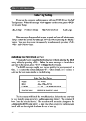
MS-6712 ATX Mainboard Entering Setup Power on the computer and the system will list all the bootable devices. You may also restart the system by pressing . When ...
MS-6712 ATX Mainboard Entering Setup Power on the computer and the system will list all the bootable devices. You may also restart the system by pressing . When ...


