User Guide
Page 2
... notice. Alternatively, please try the following help resources for FAQ, technical guide, BIOS updates, driver updates, and other countries. We take every care in the United States and/or other information: http://www.msi.com.tw/program/service/faq/ faq/esc_faq_list.php Contact our technical staff at:... http://support.msi.com.tw/ ii Intel® and Pentium® are registered trademarks of NVIDIA Corporation in...
... notice. Alternatively, please try the following help resources for FAQ, technical guide, BIOS updates, driver updates, and other countries. We take every care in the United States and/or other information: http://www.msi.com.tw/program/service/faq/ faq/esc_faq_list.php Contact our technical staff at:... http://support.msi.com.tw/ ii Intel® and Pentium® are registered trademarks of NVIDIA Corporation in...
User Guide
Page 9
D-Bracket™ 2 Connector: JDB1 2-19 Button ...2-20 Clear CMOS Button: SW2 2-20 Slots ...2-20 PCI (Peripheral Component Interconnect) Express Slots 2-21 NV SLI Technology 2-22 PCI (Peripheral Component Interconnect) Slots 2-24 PCI Interrupt Request Routing 2-24 Chapter 3 BIOS Setup 3-1 Entering Setup ...3-2 Control Keys 3-3 Getting Help 3-3 General Help
D-Bracket™ 2 Connector: JDB1 2-19 Button ...2-20 Clear CMOS Button: SW2 2-20 Slots ...2-20 PCI (Peripheral Component Interconnect) Express Slots 2-21 NV SLI Technology 2-22 PCI (Peripheral Component Interconnect) Slots 2-24 PCI Interrupt Request Routing 2-24 Chapter 3 BIOS Setup 3-1 Entering Setup ...3-2 Control Keys 3-3 Getting Help 3-3 General Help
User Guide
Page 10
Summary of RAID Configurations B-2 RAID Configuration B-3 Basic Configuration Instructions B-3 Setting Up the NVRAID BIOS B-3 Installing the RAID Driver (for bootable RAID Array B-7 NVIDIA IDE Driver/ RAID Utility Installation B-9 Installing the NVIDIA RAID Software Under W indows (for Non-bootable RAID ...
Summary of RAID Configurations B-2 RAID Configuration B-3 Basic Configuration Instructions B-3 Setting Up the NVRAID BIOS B-3 Installing the RAID Driver (for bootable RAID Array B-7 NVIDIA IDE Driver/ RAID Utility Installation B-9 Installing the NVIDIA RAID Software Under W indows (for Non-bootable RAID ...
User Guide
Page 14
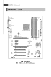
... NBFAN1 SATA 6 S ATA1 S ATA2 S ATA3 S ATA4 VI A VT6307 ( op t io n a l ) J 1 3 94 _ 1 (optional ) JUS B2 JUSB 3 SW2 BIOS JUS B1 B AT T + JDB1 JFP2 JFP1 K9N SLI Series (MS-7250 v2.X) ATX Mainboard 1-4 Ou t B:SPDIF Out (optic al) LAN Chip LAN Chip PW R3 PWR2 CP UFAN1 SYS FA N1 PCI _E1 PCI _E2 PCI _E...
... NBFAN1 SATA 6 S ATA1 S ATA2 S ATA3 S ATA4 VI A VT6307 ( op t io n a l ) J 1 3 94 _ 1 (optional ) JUS B2 JUSB 3 SW2 BIOS JUS B1 B AT T + JDB1 JFP2 JFP1 K9N SLI Series (MS-7250 v2.X) ATX Mainboard 1-4 Ou t B:SPDIF Out (optic al) LAN Chip LAN Chip PW R3 PWR2 CP UFAN1 SYS FA N1 PCI _E1 PCI _E2 PCI _E...
User Guide
Page 18
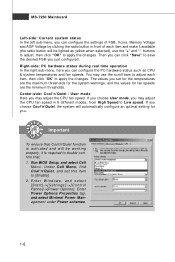
... clicking the radio button in 8 different modes, from High Speed to Low speed. If you choose User mode, you set this item to [Enable]. 2. Run BIOS Setup, and select Cell Menu. Center-side: Cool'n'Quiet / User mode Here you can configure the PC hardware status such as yellow when selected), use...
... clicking the radio button in 8 different modes, from High Speed to Low speed. If you choose User mode, you set this item to [Enable]. 2. Run BIOS Setup, and select Cell Menu. Center-side: Cool'n'Quiet / User mode Here you can configure the PC hardware status such as yellow when selected), use...
User Guide
Page 32
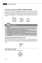
... 1. CPUFAN1 supports fan control. The system will record this status and show a warning message on tr ol . To clear the warning, you must enter the BIOS utility and clear the record. 1 CINTRU 2 GND JCI1 CD-In Connector: JCD1 This connector is provided for proper CPU cooling fan. 3. If the chassis is...
... 1. CPUFAN1 supports fan control. The system will record this status and show a warning message on tr ol . To clear the warning, you must enter the BIOS utility and clear the record. 1 CINTRU 2 GND JCI1 CD-In Connector: JCD1 This connector is provided for proper CPU cooling fan. 3. If the chassis is...
User Guide
Page 37
...1 2 Initializing Keyboard Controller. 1 2 Initializing Hard Drive Controller This will initialize IDE drive and 3 4 3 4 controller. 1 2 Testing VGA BIOS 1 2 Initializing Floppy Drive Controller This will start writing VGA sign-on This will initialize Floppy Drive and 3 4 message to the screen. 3 ... will start showing information 3 4 about logo, processor brand name, etc... Then, detect and initializethe video adapter. 1 2 EarlyChipset Initialization 3 4 BIOS Sign On 1 2 This will set low stack and boot via 4 INT 19h. 1 2 1 2 3 Testing RTC (Real Time Clock)...
...1 2 Initializing Keyboard Controller. 1 2 Initializing Hard Drive Controller This will initialize IDE drive and 3 4 3 4 controller. 1 2 Testing VGA BIOS 1 2 Initializing Floppy Drive Controller This will start writing VGA sign-on This will initialize Floppy Drive and 3 4 message to the screen. 3 ... will start showing information 3 4 about logo, processor brand name, etc... Then, detect and initializethe video adapter. 1 2 EarlyChipset Initialization 3 4 BIOS Sign On 1 2 This will set low stack and boot via 4 INT 19h. 1 2 1 2 3 Testing RTC (Real Time Clock)...
User Guide
Page 39
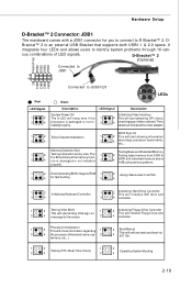
Meanwhile, read the documentation for the ex pansion card, such as jumpers, switches or BIOS configuration. 2. Also, desktop platforms with PCI Express Architecture will be designed to configure any necessary hardware or software settings for the expansion card ... starting at 2.5 Giga transfers per second over a PCI Express x16 lane for Gigabit Ethernet, TV Tuners, 1394 controllers, and general purpose I/O. The K9N SLI Series support SLI technology. 2-21 When adding or removing expansion cards, make sure that you unplug the power supply first. PCI Express x16 Slot PCI Express x1...
Meanwhile, read the documentation for the ex pansion card, such as jumpers, switches or BIOS configuration. 2. Also, desktop platforms with PCI Express Architecture will be designed to configure any necessary hardware or software settings for the expansion card ... starting at 2.5 Giga transfers per second over a PCI Express x16 lane for Gigabit Ethernet, TV Tuners, 1394 controllers, and general purpose I/O. The K9N SLI Series support SLI technology. 2-21 When adding or removing expansion cards, make sure that you unplug the power supply first. PCI Express x16 Slot PCI Express x1...
User Guide
Page 43
You may need to run the Setup program when: ² An error message appears on the BIOS Setup program and allows you to run SETUP. ² You want to configure the system for customized features. 3-1 Chapter 3 BIOS Setup BIOS Setup This chapter provides information on the screen during the system booting up, and requests you to change the default settings for optimum use.
You may need to run the Setup program when: ² An error message appears on the BIOS Setup program and allows you to run SETUP. ² You want to configure the system for customized features. 3-1 Chapter 3 BIOS Setup BIOS Setup This chapter provides information on the screen during the system booting up, and requests you to change the default settings for optimum use.
User Guide
Page 44
... On or pressing the RESET button. V1.2 refers to the BIOS version. 111506 refers to the customer as MS = all standard customers. Important 1. It is the BIOS version. You may be slightly different from the latest BIOS and should be held for better system performance. Upon boot-up..., the 1st line appearing after the memory count is usually in this BIOS was released. 3-2 The items under each BIOS category described in the format: A7250NMS V1.2 111506 where: 1st digit refers to BIOS maker as A = AMI, W = AWARD, and P = PHOENIX. 2nd - 5th digit refers ...
... On or pressing the RESET button. V1.2 refers to the BIOS version. 111506 refers to the customer as MS = all standard customers. Important 1. It is the BIOS version. You may be slightly different from the latest BIOS and should be held for better system performance. Upon boot-up..., the 1st line appearing after the memory count is usually in this BIOS was released. 3-2 The items under each BIOS category described in the format: A7250NMS V1.2 111506 where: 1st digit refers to BIOS maker as A = AMI, W = AWARD, and P = PHOENIX. 2nd - 5th digit refers ...
User Guide
Page 45
... up the sub-menu. The on-line description of the highlighted setup function is the Main Menu. Press to the main menu, just press the . BIOS Setup Control Keys Enter> Move to the previous item Move to the next item Move to the item in the right hand Select the item... you find a right pointer symbol (as shown in the right view) appears to the left hand Move to field within a sub-menu. General Help The BIOS setup program provides a General Help screen. You can be launched from this screen from field to the item in the left of the screen. Sub...
... up the sub-menu. The on-line description of the highlighted setup function is the Main Menu. Press to the main menu, just press the . BIOS Setup Control Keys Enter> Move to the previous item Move to the next item Move to the item in the right hand Select the item... you find a right pointer symbol (as shown in the right view) appears to the left hand Move to field within a sub-menu. General Help The BIOS setup program provides a General Help screen. You can be launched from this screen from field to the item in the left of the screen. Sub...
User Guide
Page 46
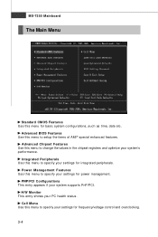
... Standard CMOS Features Use this menu for integrated peripherals. Integrated Peripherals Use this menu to setup the items of AMI® special enhanced features. Advanced BIOS Features Use this menu to specify your settings for basic system configurations, such as time, date etc. PNP/PCI Configurations This entry appears if your...
... Standard CMOS Features Use this menu for integrated peripherals. Integrated Peripherals Use this menu to setup the items of AMI® special enhanced features. Advanced BIOS Features Use this menu to specify your settings for basic system configurations, such as time, date etc. PNP/PCI Configurations This entry appears if your...
User Guide
Page 47
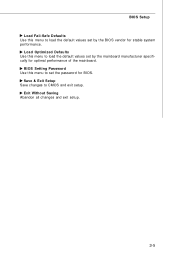
BIOS Setup Load Fail-Safe Defaults Use this menu to load the default values set by the mainboard manufacturer specifically for optimal performance of the mainboard. Save & Exit Setup Save changes to load the default values set the password for stable system performance. Load Optimized Defaults Use this menu to set by the BIOS vendor for BIOS. Exit Without Saving Abandon all changes and exit setup. 3-5 BIOS Setting Password Use this menu to CMOS and exit setup.
BIOS Setup Load Fail-Safe Defaults Use this menu to load the default values set by the mainboard manufacturer specifically for optimal performance of the mainboard. Save & Exit Setup Save changes to load the default values set the password for stable system performance. Load Optimized Defaults Use this menu to set by the BIOS vendor for BIOS. Exit Without Saving Abandon all changes and exit setup. 3-5 BIOS Setting Password Use this menu to CMOS and exit setup.
User Guide
Page 48
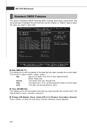
date The date from 1 to 31 can be keyed by BIOS. Read-only. Date (MM:DD:YY) This allows you to Sat, determined by numeric function keys. day Day of the week, from Jan. through Dec. ...
date The date from 1 to 31 can be keyed by BIOS. Read-only. Date (MM:DD:YY) This allows you to Sat, determined by numeric function keys. day Day of the week, from Jan. through Dec. ...
User Guide
Page 49
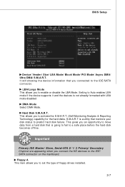
... and the devices is a utility that you to the IDE/SATA connector. S.M.A.R.T is not already formatted with LBA mode disabled. DM A M ode Select DMA Mode. BIOS Setup Device/ Vender/ Size/ LBA Mode/ Block M ode/ PIO Mode/ Async DM A/ Ultra DMA/ S.M.A.R.T. This gives you to predict hard disk failure. Setting to a safe...
... and the devices is a utility that you to the IDE/SATA connector. S.M.A.R.T is not already formatted with LBA mode disabled. DM A M ode Select DMA Mode. BIOS Setup Device/ Vender/ Size/ LBA Mode/ Block M ode/ PIO Mode/ Async DM A/ Ultra DMA/ S.M.A.R.T. This gives you to predict hard disk failure. Setting to a safe...
User Guide
Page 50
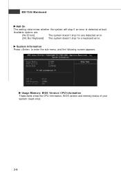
Usage Memory/ BIOS Version/ CPU Information These items show the CPU information, BIOS version and memory status of your system (read only). 3-8 System Information Press to enter the sub-menu, and the following screen appears. MS-7250 Mainboard Halt On The setting determines whether the system will stop for any detected error. [All, But Keyboard] The system doesn't stop if an error is detected at boot. Available options are: [No Errors] The system doesn't stop for a keyboard error.
Usage Memory/ BIOS Version/ CPU Information These items show the CPU information, BIOS version and memory status of your system (read only). 3-8 System Information Press to enter the sub-menu, and the following screen appears. MS-7250 Mainboard Halt On The setting determines whether the system will stop for any detected error. [All, But Keyboard] The system doesn't stop if an error is detected at boot. Available options are: [No Errors] The system doesn't stop for a keyboard error.
User Guide
Page 51
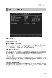
...beep. Boot Sector Protection This item allows you choose [Yes]. If this function is enabled and someone attempt to write date into this area, BIOS will skip some check items. Full Screen LOGO Display This item enables you cannot run the OS/2® operating system with DRAM larger than ...64MB. But it will shows a warning message on the bootup screen. Advanced BIOS Features BIOS Setup Quick Boot Setting the item to [Enabled] allows the system to boot within 5 seconds since it is possible if you to choose the...
...beep. Boot Sector Protection This item allows you choose [Yes]. If this function is enabled and someone attempt to write date into this area, BIOS will skip some check items. Full Screen LOGO Display This item enables you cannot run the OS/2® operating system with DRAM larger than ...64MB. But it will shows a warning message on the bootup screen. Advanced BIOS Features BIOS Setup Quick Boot Setting the item to [Enabled] allows the system to boot within 5 seconds since it is possible if you to choose the...
User Guide
Page 52
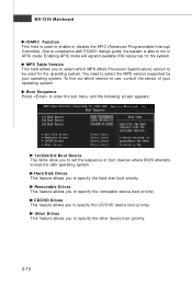
... the CD/DVD device boot priority. Removable Drives This feature allows you to select which version to use, consult the vendor of boot devices where BIOS attempts to select the MPS version supported by your operating system. You need to load the disk operating system. MPS Table Version This field allows...
... the CD/DVD device boot priority. Removable Drives This feature allows you to select which version to use, consult the vendor of boot devices where BIOS attempts to select the MPS version supported by your operating system. You need to load the disk operating system. MPS Table Version This field allows...
User Guide
Page 53
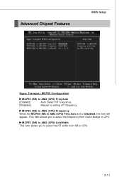
This item allows you to select the HT width from South Bridge to CPU. 3-11 M CP55 (SB) to AM 2 (CPU) Frequency W hen the MCP55 (SB) to AM2 (CPU) Freq Auto set to setting HT frequency. MCP55 (SB) to AM 2 (CPU) LinkWidth This item allows you to select the frequency from SB to CPU. Advanced Chipset Features BIOS Setup Hyper Transport MCP55 Configuration MCP55 (SB) to AM 2 (CPU) Freq Auto [Enabled] Auto Detect HT frequency. [Disabled] Manual to Disabled, the item will appear.
This item allows you to select the HT width from South Bridge to CPU. 3-11 M CP55 (SB) to AM 2 (CPU) Frequency W hen the MCP55 (SB) to AM2 (CPU) Freq Auto set to setting HT frequency. MCP55 (SB) to AM 2 (CPU) LinkWidth This item allows you to select the frequency from SB to CPU. Advanced Chipset Features BIOS Setup Hyper Transport MCP55 Configuration MCP55 (SB) to AM 2 (CPU) Freq Auto [Enabled] Auto Detect HT frequency. [Disabled] Manual to Disabled, the item will appear.

User Guide
Page 55
... [SPP]. Settings are: [Disabled] RS-232C Serial Port [Enabled] IrDA-compliant Serial Infrared Port Parallel Port There is used to decide whether to use it. BIOS Setup Onboard Lan Option ROM This item is a built-in parallel port on the on FDC or the system has no floppy drive, select [Disabled...
... [SPP]. Settings are: [Disabled] RS-232C Serial Port [Enabled] IrDA-compliant Serial Infrared Port Parallel Port There is used to decide whether to use it. BIOS Setup Onboard Lan Option ROM This item is a built-in parallel port on the on FDC or the system has no floppy drive, select [Disabled...


