User Guide
Page 2
.... AMI® is a registered trademark of International Business Machines Corporation. Alternatively, please try the following help resources for FAQ, technical guide, BIOS updates, driver updates, and other countries. Visit the MSI website for further guidance. W indows® 95/98/2000/NT/XP are registered trademarks of American Megatrends Inc. Award® is a registered trademark of Microsoft Corporation. Our...
.... AMI® is a registered trademark of International Business Machines Corporation. Alternatively, please try the following help resources for FAQ, technical guide, BIOS updates, driver updates, and other countries. Visit the MSI website for further guidance. W indows® 95/98/2000/NT/XP are registered trademarks of American Megatrends Inc. Award® is a registered trademark of Microsoft Corporation. Our...
User Guide
Page 8
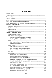
... Specifications 1-2 Mainboard Layout 1-4 Packing Checklist 1-6 MSI Special feature 1-7 Chapter 2 Hardware Setup 2-1 Quick Components Guide 2-2 CPU (Central Processing Unit 2-3 CPU Installation Procedures for Socket AM2 2-4 Installing AMD Socket AM2 CPU Cooler Set 2-5 Memory ...2-6 Dual-Channel Memory Population Rules 2-6 Installing DDRII Modules 2-7 Power Supply ...2-8 ATX 24-Pin Power Connector: PWR1 2-8 ATX 12V Power Connector: PWR3/ PWR2 2-8 Important Notification about Power Issue 2-9 Back Panel ...2-10 Connectors ...2-12 Floppy Disk Drive Connector: FDD1 2-12 ATA133 Hard...
... Specifications 1-2 Mainboard Layout 1-4 Packing Checklist 1-6 MSI Special feature 1-7 Chapter 2 Hardware Setup 2-1 Quick Components Guide 2-2 CPU (Central Processing Unit 2-3 CPU Installation Procedures for Socket AM2 2-4 Installing AMD Socket AM2 CPU Cooler Set 2-5 Memory ...2-6 Dual-Channel Memory Population Rules 2-6 Installing DDRII Modules 2-7 Power Supply ...2-8 ATX 24-Pin Power Connector: PWR1 2-8 ATX 12V Power Connector: PWR3/ PWR2 2-8 Important Notification about Power Issue 2-9 Back Panel ...2-10 Connectors ...2-12 Floppy Disk Drive Connector: FDD1 2-12 ATA133 Hard...
User Guide
Page 9
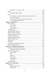
D-Bracket™ 2 Connector: JDB1 2-19 Button ...2-20 Clear CMOS Button: SW2 2-20 Slots ...2-20 PCI (Peripheral Component Interconnect) Express Slots 2-21 NV SLI Technology 2-22 PCI (Peripheral Component Interconnect) Slots 2-24 PCI Interrupt Request Routing 2-24 Chapter 3 BIOS Setup 3-1 Entering Setup ...3-2 Control Keys 3-3 Getting Help 3-3 General Help
D-Bracket™ 2 Connector: JDB1 2-19 Button ...2-20 Clear CMOS Button: SW2 2-20 Slots ...2-20 PCI (Peripheral Component Interconnect) Express Slots 2-21 NV SLI Technology 2-22 PCI (Peripheral Component Interconnect) Slots 2-24 PCI Interrupt Request Routing 2-24 Chapter 3 BIOS Setup 3-1 Entering Setup ...3-2 Control Keys 3-3 Getting Help 3-3 General Help
User Guide
Page 10
Summary of RAID Configurations B-2 RAID Configuration B-3 Basic Configuration Instructions B-3 Setting Up the NVRAID BIOS B-3 Installing the RAID Driver (for bootable RAID Array B-7 NVIDIA IDE Driver/ RAID Utility Installation B-9 Installing the NVIDIA RAID Software Under W indows (for Non-bootable RAID Array B-9 Initializing and Using the Disk Array B-10 NVRAID Management Utility B-12 Viewing RAID Array Configurations B-12 Setting Up a Spare RAID Disk B-13 Morphing From One RAID Array to Another B-17 Hot Plug Array B-18 Initializing a RAID Array B-19 Rebuilding a RAID Array B-...
Summary of RAID Configurations B-2 RAID Configuration B-3 Basic Configuration Instructions B-3 Setting Up the NVRAID BIOS B-3 Installing the RAID Driver (for bootable RAID Array B-7 NVIDIA IDE Driver/ RAID Utility Installation B-9 Installing the NVIDIA RAID Software Under W indows (for Non-bootable RAID Array B-9 Initializing and Using the Disk Array B-10 NVRAID Management Utility B-12 Viewing RAID Array Configurations B-12 Setting Up a Spare RAID Disk B-13 Morphing From One RAID Array to Another B-17 Hot Plug Array B-18 Initializing a RAID Array B-19 Rebuilding a RAID Array B-...
User Guide
Page 12
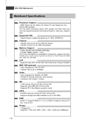
... FX and Sempronin the socket AM2 package. (For the latest information about CPU, please visit http://www.msi. nVIDIA® nForce 570 SLI for K9N Ultra Series Memory Support - ms i . Supports Dual LAN 10/100/1000 Fast Ethernet by nForce 570 SLI/ nForce 570 Floppy - 1 floppy port - SATA1~6 supports RAID 0/ 1/ 0+1 or RAID 5 mode by Vitesse VSC8601 IEEE 1394 (optional) - Flexible 8-channel audio with 360K, 720K, 1.2M, 1.44M and 2.88Mbytes 1-2 Supports storage and data transfers...
... FX and Sempronin the socket AM2 package. (For the latest information about CPU, please visit http://www.msi. nVIDIA® nForce 570 SLI for K9N Ultra Series Memory Support - ms i . Supports Dual LAN 10/100/1000 Fast Ethernet by nForce 570 SLI/ nForce 570 Floppy - 1 floppy port - SATA1~6 supports RAID 0/ 1/ 0+1 or RAID 5 mode by Vitesse VSC8601 IEEE 1394 (optional) - Flexible 8-channel audio with 360K, 720K, 1.2M, 1.44M and 2.88Mbytes 1-2 Supports storage and data transfers...
User Guide
Page 13
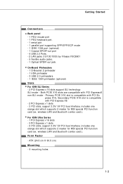
... Secondary PCIE X16 slot is compatible with PCI Expressx8 non-SLI mode - wireless LAN and bluetooth combo card.). For K9N Ultra Series - 1 PCI Express x 16 slots - 3 PCI Express x 1 slots - 3 PCI slots, support 3.3V/ 5V PCI bus Interface, includes one orange slot which supports 2 master for MSI special PCI function card (ex. On-Board Pinheaders - 1 D-Bracket 2 pinheader - 1 IrDA pinheader - 3 USB 2.0 pinheaders - 1 IEEE 1394 pinheader (optional) Slots For K9N SLI Series - 2 PCI Express x 16 slots support SLI technology SLI mode - wireless LAN and bluetooth combo card.). Form Factor - ATX...
... Secondary PCIE X16 slot is compatible with PCI Expressx8 non-SLI mode - wireless LAN and bluetooth combo card.). For K9N Ultra Series - 1 PCI Express x 16 slots - 3 PCI Express x 1 slots - 3 PCI slots, support 3.3V/ 5V PCI bus Interface, includes one orange slot which supports 2 master for MSI special PCI function card (ex. On-Board Pinheaders - 1 D-Bracket 2 pinheader - 1 IrDA pinheader - 3 USB 2.0 pinheaders - 1 IEEE 1394 pinheader (optional) Slots For K9N SLI Series - 2 PCI Express x 16 slots support SLI technology SLI mode - wireless LAN and bluetooth combo card.). Form Factor - ATX...
User Guide
Page 17
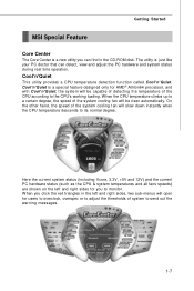
... CPU & system temperatures and all fans speeds) are shown on the left and right sides, two sub-menus will be risen automatically. Cool'n'Quiet is a special feature designed only for AMD® Athlon64 processor, and with Cool'n'Quiet, the system will open for users to overclock,...CPU according to its normal degree. W hen you to send out the warning messages. 1-7 The utility is just like your PC doctor that can find in the left and right sides for you click the red triangles in the CD-ROM disk. Getting Started MSI Special Feature Core Center The Core Center is a new utility...
... CPU & system temperatures and all fans speeds) are shown on the left and right sides, two sub-menus will be risen automatically. Cool'n'Quiet is a special feature designed only for AMD® Athlon64 processor, and with Cool'n'Quiet, the system will open for users to overclock,...CPU according to its normal degree. W hen you to send out the warning messages. 1-7 The utility is just like your PC doctor that can find in the left and right sides for you click the red triangles in the CD-ROM disk. Getting Started MSI Special Feature Core Center The Core Center is a new utility...
User Guide
Page 26
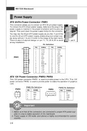
... power to avoid wrong installation. If you'd like . This 12V power connector PW R2 is used to provide power to the CPU. Power supply of 350 watts (and above) is also a foolproof design on pin 11, 12, 23 & 24 to stable the operation of graphics card. To connect the ATX 24-pin power supply, make sure the plug of the mainboard. 2. You may use the 20-pin ATX power supply, please plug your power supply along with pin 1 & pin...
... power to avoid wrong installation. If you'd like . This 12V power connector PW R2 is used to provide power to the CPU. Power supply of 350 watts (and above) is also a foolproof design on pin 11, 12, 23 & 24 to stable the operation of graphics card. To connect the ATX 24-pin power supply, make sure the plug of the mainboard. 2. You may use the 20-pin ATX power supply, please plug your power supply along with pin 1 & pin...
User Guide
Page 37
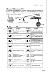
...LED will start detecting CPU clock, 4 checking type ofvideo onboard. Then, detect and initializethe video adapter. 1 2 EarlyChipset Initialization 3 4 BIOS Sign On 1 2 This will hang if the memory mod4 ule is an external USB Bracket that supports both USB1.1 & 2.0 specs. Hardware Setup D-Bracket™ 2 Connector: JDB1 The mainboard comes with a JDB1 connector for fast booting. 3 4 1 2 Initializing Keyboard Controller. 1 2 Initializing Hard Drive Controller This will initialize IDE drive and 3 4 3 4 controller. 1 2 Testing VGA BIOS 1 2 Initializing Floppy...
...LED will start detecting CPU clock, 4 checking type ofvideo onboard. Then, detect and initializethe video adapter. 1 2 EarlyChipset Initialization 3 4 BIOS Sign On 1 2 This will hang if the memory mod4 ule is an external USB Bracket that supports both USB1.1 & 2.0 specs. Hardware Setup D-Bracket™ 2 Connector: JDB1 The mainboard comes with a JDB1 connector for fast booting. 3 4 1 2 Initializing Keyboard Controller. 1 2 Initializing Hard Drive Controller This will initialize IDE drive and 3 4 3 4 controller. 1 2 Testing VGA BIOS 1 2 Initializing Floppy...
User Guide
Page 38
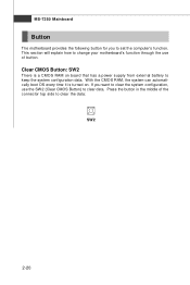
... configuration, use of the connector top side to keep the system configuration data. If you to clear data. This section will explain how to change your motherboard's function through the use the SW 2 (Clear CMOS Button) to set the computer's function. Press the button in the middle of button. Clear CMOS Button: SW2 There is turned on board that has a power supply from external battery to clear the data: SW2 2-20 With the CMOS RAM...
... configuration, use of the connector top side to keep the system configuration data. If you to clear data. This section will explain how to change your motherboard's function through the use the SW 2 (Clear CMOS Button) to set the computer's function. Press the button in the middle of button. Clear CMOS Button: SW2 There is turned on board that has a power supply from external battery to clear the data: SW2 2-20 With the CMOS RAM...
User Guide
Page 39
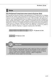
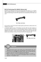
... Setup Slots PCI (Peripheral Component Interconnect) Express Slots PCI Express architecture provides a high performance I /O. Also, desktop platforms with transfer rates starting at 2.5 Giga transfers per second over a PCI Express x16 lane for graphics controllers, while PCI Express x1 supports transfer rate of 250 MB/s. PCI Express x16 Slot PCI Express x1 Slot Important 1. The K9N SLI Series support SLI technology. 2-21 When adding or removing expansion cards, make sure that you unplug the power supply first. Moreover, PCI Express architecture provides a high performance graphics...
... Setup Slots PCI (Peripheral Component Interconnect) Express Slots PCI Express architecture provides a high performance I /O. Also, desktop platforms with transfer rates starting at 2.5 Giga transfers per second over a PCI Express x16 lane for graphics controllers, while PCI Express x1 supports transfer rate of 250 MB/s. PCI Express x16 Slot PCI Express x1 Slot Important 1. The K9N SLI Series support SLI technology. 2-21 When adding or removing expansion cards, make sure that you unplug the power supply first. Moreover, PCI Express architecture provides a high performance graphics...
User Guide
Page 40
SLI Video Link Card If you intend to use the SLI mode for demonstration only. Please note that although you have installed two graphics cards, only the video outputs on the model you connect an adequate power supply to the PWR2 connector (or to the power connection on PCI Express x16 slots. The appearance of your mainboard may vary depending on the first card will work. W ith two cards installed, an SLI bridge card is required to connect the...
SLI Video Link Card If you intend to use the SLI mode for demonstration only. Please note that although you have installed two graphics cards, only the video outputs on the model you connect an adequate power supply to the PWR2 connector (or to the power connection on PCI Express x16 slots. The appearance of your mainboard may vary depending on the first card will work. W ith two cards installed, an SLI bridge card is required to connect the...
User Guide
Page 49
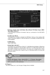
... to Auto enables LBA mode if the device supports it and the devices is not already formatted with LBA mode disabled. S.M.A.R.T is going to fail to the IDE/SATA connector. Floppy A This item allows you to the IDE/ SATA connector on the mainboard. LBA/Large M ode This allows you to predict hard disk failure. Important Primary IDE Master/ Slave, Serial-ATA 0/ 1/ 2 Primary/ Secondary Channel are appearing when you connected to a safe place before the hard disk...
... to Auto enables LBA mode if the device supports it and the devices is not already formatted with LBA mode disabled. S.M.A.R.T is going to fail to the IDE/SATA connector. Floppy A This item allows you to the IDE/ SATA connector on the mainboard. LBA/Large M ode This allows you to predict hard disk failure. Important Primary IDE Master/ Slave, Serial-ATA 0/ 1/ 2 Primary/ Secondary Channel are appearing when you connected to a safe place before the hard disk...

User Guide
Page 55
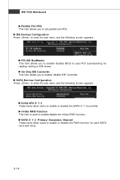
... Parallel Port only, choose [SPP]. To operate the onboard parallel port in parallel port on the on FDC or the system has no floppy drive, select [Disabled] in ECP mode only. BIOS Setup Onboard Lan Option ROM This item is a built-in the EPP mode simultaneously, choose [EPP]. I /O chipset that provides Standard, ECP, and EPP features. IR Function This setting allows you to invoke the Boot ROM of the onboard LAN Chip.
... Parallel Port only, choose [SPP]. To operate the onboard parallel port in parallel port on the on FDC or the system has no floppy drive, select [Disabled] in ECP mode only. BIOS Setup Onboard Lan Option ROM This item is a built-in the EPP mode simultaneously, choose [EPP]. I /O chipset that provides Standard, ECP, and EPP features. IR Function This setting allows you to invoke the Boot ROM of the onboard LAN Chip.
User Guide
Page 56
... IDE drives. nVidia RAID Function This item is used PCI busmastering for each SATA hard disk drive. 3-14 SATA 0/ 1/ 2 Primary/ Secondary Channel These items allow users to enable/ disable IDE Controller. SATA Devices Configuration Press to enter the sub-menu and the following screen appears: PCI IDE BusMaster This item allows you to enable or disable the SATA 0/ 1/ 2controller. IDE Devices Configuration Press to enter the sub-menu and the following screen appears: Serial-ATA 0/ 1/ 2 These items allow users to set parallel port IRQ. MS-7250 Mainboard Parallel Port...
... IDE drives. nVidia RAID Function This item is used PCI busmastering for each SATA hard disk drive. 3-14 SATA 0/ 1/ 2 Primary/ Secondary Channel These items allow users to enable/ disable IDE Controller. SATA Devices Configuration Press to enter the sub-menu and the following screen appears: PCI IDE BusMaster This item allows you to enable or disable the SATA 0/ 1/ 2controller. IDE Devices Configuration Press to enter the sub-menu and the following screen appears: Serial-ATA 0/ 1/ 2 These items allow users to set parallel port IRQ. MS-7250 Mainboard Parallel Port...
User Guide
Page 60
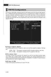
... experienced users should set to operate at speeds nearing the speed the CPU itself uses when communicating with its special components. PCI Latency Timer This item controls how long each PCI slot. 3-18 MS-7250 Mainboard PNP/PCI Configurations This section describes configuring the PCI bus system and PnP (Plug & Play) feature. PCI, or Peripheral Component Interconnect, is your primary graphics adapter. For better PCI performance, you should make any changes to...
... experienced users should set to operate at speeds nearing the speed the CPU itself uses when communicating with its special components. PCI Latency Timer This item controls how long each PCI slot. 3-18 MS-7250 Mainboard PNP/PCI Configurations This section describes configuring the PCI bus system and PnP (Plug & Play) feature. PCI, or Peripheral Component Interconnect, is your primary graphics adapter. For better PCI performance, you should make any changes to...
User Guide
Page 62
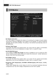
.... SYSFAN Control It provides the Smart Fan system which can control the fan speed automatically depending on the current temperature to choose the CPU fan pin number of your system. System/ CPU Temperature, SYSFAN/ CPUFAN Speed, CPU Vcore, +12.0V, +5.0V, +3.3V, These items display the current status of all of the field will automatically return to [Reset]. MS-7250 Mainboard H/W Monitor Chassis Intrusion The field enables or disables the feature...
.... SYSFAN Control It provides the Smart Fan system which can control the fan speed automatically depending on the current temperature to choose the CPU fan pin number of your system. System/ CPU Temperature, SYSFAN/ CPUFAN Speed, CPU Vcore, +12.0V, +5.0V, +3.3V, These items display the current status of all of the field will automatically return to [Reset]. MS-7250 Mainboard H/W Monitor Chassis Intrusion The field enables or disables the feature...
User Guide
Page 67
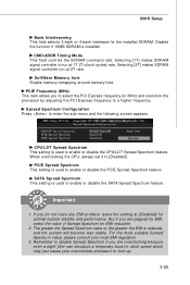
... PCI Express frequency (in clock speed which may just cause your local EMI regulation. 3. PCIE Frequency (MHz) This item allows you do not have any EMI problem, leave the setting at 1T (T=clock cycles) rate. CPU/LDT Spread Spectrum This setting is used to [Disabled]. But if you are plagued by adjusting the PCI Express frequency to run at 2T rate. SoftWare Memory hole Enable memory remapping around memory hole. W hen overclocking the CPU...
... PCI Express frequency (in clock speed which may just cause your local EMI regulation. 3. PCIE Frequency (MHz) This item allows you do not have any EMI problem, leave the setting at 1T (T=clock cycles) rate. CPU/LDT Spread Spectrum This setting is used to [Disabled]. But if you are plagued by adjusting the PCI Express frequency to run at 2T rate. SoftWare Memory hole Enable memory remapping around memory hole. W hen overclocking the CPU...

User Guide
Page 95
... part of Integrated Peripherals in BIOS before configuring the NVRAID BIOS. The default RAID Mode is set to Mirrori ng and Striping Block is set up the NVRAID BIOS. After that has the RAID driver to copy and install the nForce RAID software. (Check p.B-7 for details.) 4. NVRAID BIOS setup lets you choose the RAID array type and which hard drives you to press F10. Bootable RAID Array 1. Boot from the W indows CD, use the floppy disk...
... part of Integrated Peripherals in BIOS before configuring the NVRAID BIOS. The default RAID Mode is set to Mirrori ng and Striping Block is set up the NVRAID BIOS. After that has the RAID driver to copy and install the nForce RAID software. (Check p.B-7 for details.) 4. NVRAID BIOS setup lets you choose the RAID array type and which hard drives you to press F10. Bootable RAID Array 1. Boot from the W indows CD, use the floppy disk...
User Guide
Page 99
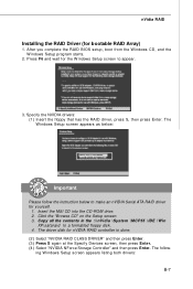
After you complete the RAID BIOS setup, boot from the W indows CD, and the W indows Setup program starts. 2. The W indows Setup screen appears as below to make an nVIDIA Serial ATA RAID driver for the W indows Setup screen to a formatted floppy disk. 4. Insert the MSI CD into the CD-ROM drive. 2. Specify the NVIDIA drivers: (1) Insert the floppy that has the RAID driver, press S, then press Enter. The follow the instruction below : Important Please follow...
After you complete the RAID BIOS setup, boot from the W indows CD, and the W indows Setup program starts. 2. The W indows Setup screen appears as below to make an nVIDIA Serial ATA RAID driver for the W indows Setup screen to a formatted floppy disk. 4. Insert the MSI CD into the CD-ROM drive. 2. Specify the NVIDIA drivers: (1) Insert the floppy that has the RAID driver, press S, then press Enter. The follow the instruction below : Important Please follow...


