

User Guide
Page 2
... properties of M ICRO-STAR INTERNATIONAL. Revision History Revision V1.0 Revision History First release for PCB 1.0 Date April 2006 Technical Support If a problem arises with your place of purchase or local distributor. Visit the MSI website for further guidance. Alternatively, please try the following help resources for FAQ, technical guide, BIOS updates, driver updates, and other countries. AMD, Athlon™, Athlon...
... properties of M ICRO-STAR INTERNATIONAL. Revision History Revision V1.0 Revision History First release for PCB 1.0 Date April 2006 Technical Support If a problem arises with your place of purchase or local distributor. Visit the MSI website for further guidance. Alternatively, please try the following help resources for FAQ, technical guide, BIOS updates, driver updates, and other countries. AMD, Athlon™, Athlon...

User Guide
Page 8
... Started 1-1 Mainboard Specifications 1-2 Mainboard Layout 1-4 Packing Checklist 1-5 Chapter 2 Hardware Setup 2-1 Quick Components Guide 2-2 CPU (Central Processing Unit 2-3 CPU Installation Procedures for Socket AM2 2-4 Installing AMD Socket AM2 CPU Cooler Set 2-5 Memory ...2-6 Dual-Channel Memory Population Rules 2-6 Installing DDRII Modules 2-7 Power Supply ...2-8 ATX 24-Pin Power Connector: PWR1 2-8 ATX 12V Power Connector: PWR3/ PWR2 2-8 Important Notification about Power Issue 2-9 Back Panel ...2-10 Connectors ...2-12 Floppy Disk Drive Connector: FDD1 2-12 ATA133 Hard Disk...
... Started 1-1 Mainboard Specifications 1-2 Mainboard Layout 1-4 Packing Checklist 1-5 Chapter 2 Hardware Setup 2-1 Quick Components Guide 2-2 CPU (Central Processing Unit 2-3 CPU Installation Procedures for Socket AM2 2-4 Installing AMD Socket AM2 CPU Cooler Set 2-5 Memory ...2-6 Dual-Channel Memory Population Rules 2-6 Installing DDRII Modules 2-7 Power Supply ...2-8 ATX 24-Pin Power Connector: PWR1 2-8 ATX 12V Power Connector: PWR3/ PWR2 2-8 Important Notification about Power Issue 2-9 Back Panel ...2-10 Connectors ...2-12 Floppy Disk Drive Connector: FDD1 2-12 ATA133 Hard Disk...
User Guide
Page 9
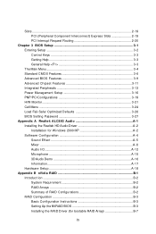
Slots ...2-19 PCI (Peripheral Component Interconnect) Express Slots 2-19 PCI Interrupt Request Routing 2-20 Chapter 3 BIOS Setup 3-1 Entering Setup ...3-2 Control Keys 3-3 Getting Help 3-3 General Help
Slots ...2-19 PCI (Peripheral Component Interconnect) Express Slots 2-19 PCI Interrupt Request Routing 2-20 Chapter 3 BIOS Setup 3-1 Entering Setup ...3-2 Control Keys 3-3 Getting Help 3-3 General Help
User Guide
Page 12
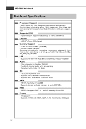
... Max) - 4 DDRII DIMMs (240-pin) (For more information on compatible components, please visit http:/ / w w w . Flexible 8-channel audio with 360K, 720K, 1.2M, 1.44M and 2.88Mbytes 1-2 Supports Ultra DMA 66/100/133 mode - SATA1~4 supports RAID 0/ 1 or 0+1 mode by nForce 550 - Compliant with Azalia 1.0 Spec IDE - 1 IDE port by nForce 550 Floppy - 1 floppy port - Supports PIO, Bus Master operation mode SATA - 4 SATA II ports by Vitesse VSC8601 Audio - ph p) LAN - c om. HyperTransport supporting speed up to 1GHz (2000MT/s) Chipset - Supports 10...
... Max) - 4 DDRII DIMMs (240-pin) (For more information on compatible components, please visit http:/ / w w w . Flexible 8-channel audio with 360K, 720K, 1.2M, 1.44M and 2.88Mbytes 1-2 Supports Ultra DMA 66/100/133 mode - SATA1~4 supports RAID 0/ 1 or 0+1 mode by nForce 550 - Compliant with Azalia 1.0 Spec IDE - 1 IDE port by nForce 550 Floppy - 1 floppy port - Supports PIO, Bus Master operation mode SATA - 4 SATA II ports by Vitesse VSC8601 Audio - ph p) LAN - c om. HyperTransport supporting speed up to 1GHz (2000MT/s) Chipset - Supports 10...

User Guide
Page 16
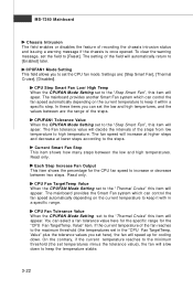
... as the CPU & system temperatures and all fans speeds) are shown on the left and right sides, two sub-menus will open for users to overclock, overspec or to adjust the thresholds of the system cooling fan will slow down instantly when the CPU temperature descends to monitor. MS-7260 Mainboard MSI Special Feature Core Center The Core Center is a new utility you can detect...
... as the CPU & system temperatures and all fans speeds) are shown on the left and right sides, two sub-menus will open for users to overclock, overspec or to adjust the thresholds of the system cooling fan will slow down instantly when the CPU temperature descends to monitor. MS-7260 Mainboard MSI Special Feature Core Center The Core Center is a new utility you can detect...

User Guide
Page 25
... the CPU. Then push down the power supply firmly into the connector. There is used to provide power to avoid wrong installation. Maker sure that all the connectors are aligned. Power supply of the mainboard. 2. If you to ensure stable operation of 350 watts (and above) is inserted in the proper orientation and the pins are connected to proper ATX power supplies to connect an ATX 24-pin power supply. JPW1...
... the CPU. Then push down the power supply firmly into the connector. There is used to provide power to avoid wrong installation. Maker sure that all the connectors are aligned. Power supply of the mainboard. 2. If you to ensure stable operation of 350 watts (and above) is inserted in the proper orientation and the pins are connected to proper ATX power supplies to connect an ATX 24-pin power supply. JPW1...

User Guide
Page 29
... The mainboard has a 32-bit Enhanced PCI IDE and Ultra DMA 66/100/133 controller that provides PIO mode 0~4, Bus Master, and Ultra DMA 66/ 100/133 function. You must configure the second drive to Slave mode by setting its jumper. Refer to 133 megabytes (MB) per second. You can connect a Master and a Slave drive. IDE1 (Primary IDE Connector) IDE1 can connect hard disk drives, CD-ROM and other IDE devices. MS-7260 Mainboard Connectors Floppy Disk Drive Connector...
... The mainboard has a 32-bit Enhanced PCI IDE and Ultra DMA 66/100/133 controller that provides PIO mode 0~4, Bus Master, and Ultra DMA 66/ 100/133 function. You must configure the second drive to Slave mode by setting its jumper. Refer to 133 megabytes (MB) per second. You can connect a Master and a Slave drive. IDE1 (Primary IDE Connector) IDE1 can connect hard disk drives, CD-ROM and other IDE devices. MS-7260 Mainboard Connectors Floppy Disk Drive Connector...

User Guide
Page 35
... is on . Then return to keep the data of jumper. With the CMOS RAM, the system can clear CMOS by shorting 2-3 pin while the system is a CMOS RAM onboard that has a power supply from external battery to 1-2 pin position. If you to set the JCMOS1 (Clear CMOS Jumper ) to change your motherboard's function through the use of system configuration. Avoid clearing the CMOS while the system is turned on ; This section will explain how to...
... is on . Then return to keep the data of jumper. With the CMOS RAM, the system can clear CMOS by shorting 2-3 pin while the system is a CMOS RAM onboard that has a power supply from external battery to 1-2 pin position. If you to set the JCMOS1 (Clear CMOS Jumper ) to change your motherboard's function through the use of system configuration. Avoid clearing the CMOS while the system is turned on ; This section will explain how to...
User Guide
Page 36
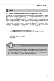
PCI Express x16 Slot PCI Express x1 Slot Important 1. Hardware Setup Slots PCI (Peripheral Component Interconnect) Express Slots PCI Express architecture provides a high performance I /O. When adding or removing expansion cards, make sure that you unplug the power supply first. Moreover, PCI Express architecture provides a high performance graphics infrastructure for Desktop Platforms doubling the capability of existing AGP 8x designs with transfer rates starting at 2.5 Giga transfers per second over a PCI Express x16 lane for graphics controllers, while PCI Express x1 supports ...
PCI Express x16 Slot PCI Express x1 Slot Important 1. Hardware Setup Slots PCI (Peripheral Component Interconnect) Express Slots PCI Express architecture provides a high performance I /O. When adding or removing expansion cards, make sure that you unplug the power supply first. Moreover, PCI Express architecture provides a high performance graphics infrastructure for Desktop Platforms doubling the capability of existing AGP 8x designs with transfer rates starting at 2.5 Giga transfers per second over a PCI Express x16 lane for graphics controllers, while PCI Express x1 supports ...
User Guide
Page 44
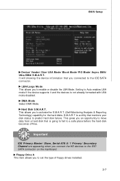
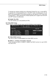
Setting to Auto enables LBA mode if the device supports it and the devices is a utility that monitors your disk status to predict hard disk failure. Hard Disk S.M.A.R.T. Important IDE Primary Master/ Slave, Serial-ATA 0/ 1 Primary/ Secondary Channel are appearing when you to the IDE/ SATA connector on the mainboard. DM A M ode Select DMA Mode. This allows you connect the HD devices to activate the S.M.A.R.T. (Self-Monitoring Analysis & Reporting Technology) capability for the hard disks. S.M.A.R.T is not already formatted with...
Setting to Auto enables LBA mode if the device supports it and the devices is a utility that monitors your disk status to predict hard disk failure. Hard Disk S.M.A.R.T. Important IDE Primary Master/ Slave, Serial-ATA 0/ 1 Primary/ Secondary Channel are appearing when you to the IDE/ SATA connector on the mainboard. DM A M ode Select DMA Mode. This allows you connect the HD devices to activate the S.M.A.R.T. (Self-Monitoring Analysis & Reporting Technology) capability for the hard disks. S.M.A.R.T is not already formatted with...
User Guide
Page 46
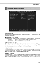
... with DRAM larger than 64MB. Setting to [On] will skip some check items. Full Screen LOGO Display This item enables you cannot run in APIC mode. Boot Up NumLock LED This setting is to set the Num Lock status when the system is powered on. Setting to [Off] will expand available IRQ resources for the system. 3-9 Enabling APIC mode will allow users to use the arrow keys...
... with DRAM larger than 64MB. Setting to [On] will skip some check items. Full Screen LOGO Display This item enables you cannot run in APIC mode. Boot Up NumLock LED This setting is to set the Num Lock status when the system is powered on. Setting to [Off] will expand available IRQ resources for the system. 3-9 Enabling APIC mode will allow users to use the arrow keys...

User Guide
Page 50
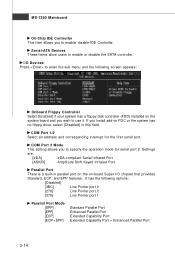
... to enable/disable the onboard USB 1.1/ 2.0 controller. Onboard Audio Controller This setting is used to enable/disable the onboard LAN controller. Integrated Peripherals BIOS Setup USB / 2.0 Controller This setting allows you need to use a USB-interfaced device in the operating system. Onboard LAN Controller These items are used to IDE drives. 3-13 On-Chip ATA Devices Press to enter the sub-menu and the following screen appears: PCI IDE BusMaster This item allows you to enable/ disable BIOS to used PCI busmastering for reading/ writing to enable/disable the onboard audio controller...
... to enable/disable the onboard USB 1.1/ 2.0 controller. Onboard Audio Controller This setting is used to enable/disable the onboard LAN controller. Integrated Peripherals BIOS Setup USB / 2.0 Controller This setting allows you need to use a USB-interfaced device in the operating system. Onboard LAN Controller These items are used to IDE drives. 3-13 On-Chip ATA Devices Press to enter the sub-menu and the following screen appears: PCI IDE BusMaster This item allows you to enable/ disable BIOS to used PCI busmastering for reading/ writing to enable/disable the onboard audio controller...
User Guide
Page 51
... to use it. COM Port 2 Mode This setting allows you to enable/ disable IDE Controller. Settings are: [IrDA] IrDA-compliant Serial Infrared Port [ASKIR] Amplitude Shift Keyed Infrared Port Parallel Port There is a built-in this field. It has the following screen appears: Onboard Floppy Controller Select [Enabled] if your system has a floppy disk controller (FDD) installed on FDC or the system has no floppy drive, select [Disabled] in parallel port on the on-board Super I /O Devices Press to enter...
... to use it. COM Port 2 Mode This setting allows you to enable/ disable IDE Controller. Settings are: [IrDA] IrDA-compliant Serial Infrared Port [ASKIR] Amplitude Shift Keyed Infrared Port Parallel Port There is a built-in this field. It has the following screen appears: Onboard Floppy Controller Select [Enabled] if your system has a floppy disk controller (FDD) installed on FDC or the system has no floppy drive, select [Disabled] in parallel port on the on-board Super I /O Devices Press to enter...
User Guide
Page 52
... you to enable/disable the nVidia RAID function. nVidia RAID Setup Press to enter the sub-menu and the following screen appears: nVidia RAID Function This item is used to set parallel port IRQ. BIOS Setup To operate the onboard parallel port as Standard Parallel Port only, choose [SPP]. Choosing [ECP + EPP] will operate in the EPP mode simultaneously, choose [EPP]. SATA 0/ 1 Primary/ Secondary Channel These itemsallow users to support both the...
... you to enable/disable the nVidia RAID function. nVidia RAID Setup Press to enter the sub-menu and the following screen appears: nVidia RAID Function This item is used to set parallel port IRQ. BIOS Setup To operate the onboard parallel port as Standard Parallel Port only, choose [SPP]. Choosing [ECP + EPP] will operate in the EPP mode simultaneously, choose [EPP]. SATA 0/ 1 Primary/ Secondary Channel These itemsallow users to support both the...

User Guide
Page 56
... This setting specifies which graphics card is a system which allows I/O devices to higher values. PCI Latency Timer This item controls how long each PCI slot. 3-19 BIOS Setup PNP/PCI Configurations This section describes configuring the PCI bus system and PnP (Plug & Play) feature. W hen set the item to operate at speeds nearing the speed the CPU itself uses when communicating with its special components. For better PCI performance, you should make any changes...
... This setting specifies which graphics card is a system which allows I/O devices to higher values. PCI Latency Timer This item controls how long each PCI slot. 3-19 BIOS Setup PNP/PCI Configurations This section describes configuring the PCI bus system and PnP (Plug & Play) feature. W hen set the item to operate at speeds nearing the speed the CPU itself uses when communicating with its special components. For better PCI performance, you should make any changes...
User Guide
Page 59
... set the CPU fan mode. The mainboard provides another Smart Fan system which can select a fan tolerance value here for the specific range for cooling down to [Reset]. Value" plus the tolerance values you set the low and high tempertures, and the values between are : [Step Smart Fan], [Thermal Cruise], [Disabled]. MS-7260 Mainboard Chassis Intrusion The field enables or disables the feature of the steps from low temperature to high temperature. Settings...
... set the CPU fan mode. The mainboard provides another Smart Fan system which can select a fan tolerance value here for the specific range for cooling down to [Reset]. Value" plus the tolerance values you set the low and high tempertures, and the values between are : [Step Smart Fan], [Thermal Cruise], [Disabled]. MS-7260 Mainboard Chassis Intrusion The field enables or disables the feature of the steps from low temperature to high temperature. Settings...
User Guide
Page 66
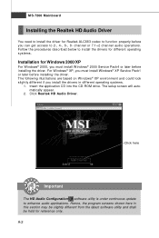
... you can get access to enhance audio applications. Click Realtek HD Audio Driver. The following illustrations are based on W indows® XP environment and could look slightly different if you must install W indows® 2000 Service Pack4 or later before installing the driver. The setup screen will automatically appear. 2. A-2 channel or 7.1+2 channel audio operations. Click here Important The HD Audio Configuration software utility is under continuous update to 2-, 4-, 6-, 8-
... you can get access to enhance audio applications. Click Realtek HD Audio Driver. The following illustrations are based on W indows® XP environment and could look slightly different if you must install W indows® 2000 Service Pack4 or later before installing the driver. The setup screen will automatically appear. 2. A-2 channel or 7.1+2 channel audio operations. Click here Important The HD Audio Configuration software utility is under continuous update to 2-, 4-, 6-, 8-

User Guide
Page 88
... in BIOS.) 2. Entering the RAID BIOS Setup 1. Choose the hard disks that are to Optimal. Setting Up the NVRAID BIOS Be sure to enable the SATA 0/ 1 Primary/ Secondary Channel in BIOS before configuring the NVRAID BIOS. The PC will appear. The default RAID Mode is set to loading the OS. 2. nVidia RAID RAID Configuration Basic Configuration Instructions The following are the basic steps for details.) 4. Enter the W indows OS, run the W indows nForce Setup application and install the RAID software...
... in BIOS.) 2. Entering the RAID BIOS Setup 1. Choose the hard disks that are to Optimal. Setting Up the NVRAID BIOS Be sure to enable the SATA 0/ 1 Primary/ Secondary Channel in BIOS before configuring the NVRAID BIOS. The PC will appear. The default RAID Mode is set to loading the OS. 2. nVidia RAID RAID Configuration Basic Configuration Instructions The following are the basic steps for details.) 4. Enter the W indows OS, run the W indows nForce Setup application and install the RAID software...

User Guide
Page 92
... floppy disk. 4. Click the "Browse CD" on the Setup screen. 3. Copy all the contents in the :\\nVidia \System \MCP55 \IDE \Win XP\sataraid to make an nVIDIA Serial ATA RAID driver for bootable RAID Array) 1. The driver disk for the W indows Setup screen to appear. 3. After you complete the RAID BIOS setup, boot from the W indows CD, and the W indows Setup program starts. 2. Press F6 and wait for nVIDIA RAID controller is...
... floppy disk. 4. Click the "Browse CD" on the Setup screen. 3. Copy all the contents in the :\\nVidia \System \MCP55 \IDE \Win XP\sataraid to make an nVIDIA Serial ATA RAID driver for bootable RAID Array) 1. The driver disk for the W indows Setup screen to appear. 3. After you complete the RAID BIOS setup, boot from the W indows CD, and the W indows Setup program starts. 2. Press F6 and wait for nVIDIA RAID controller is...

User Guide
Page 102
... the new array involves multiple steps. From RAID 1 to RAID 1 Specific Morphing Requirements The following table lists the disk requirements for a new RAID array for morphing, a process of disks. m >= n - 1 RAID 5 RAID 1 ** Not a valid combination ** RAID 0+1 m >= 2 x (n -1) ; B-17 NVIDIA RAID allows the end user to change the current state of a disk or a current array to a new RAID configuration, the process of RAID 0 disks. where m must be an even number of...
... the new array involves multiple steps. From RAID 1 to RAID 1 Specific Morphing Requirements The following table lists the disk requirements for a new RAID array for morphing, a process of disks. m >= n - 1 RAID 5 RAID 1 ** Not a valid combination ** RAID 0+1 m >= 2 x (n -1) ; B-17 NVIDIA RAID allows the end user to change the current state of a disk or a current array to a new RAID configuration, the process of RAID 0 disks. where m must be an even number of...

