
User Guide
Page 2
..., please try the following help resources for FAQ, technical guide, BIOS updates, driver updates, and other information: http://www.msi.com.tw/program/service/faq/ faq/esc_faq_list.php Contact our technical staff at: support@msi.com.tw ii PS/2 and OS®/2 are registered trademarks of... trademarks of their respective owners. W indows® 95/98/2000/NT/XP are registered trademarks of Intel Corporation. Visit the MSI website for further guidance. Trademarks All trademarks are under continual improvement and we reserve the right to the correctness of its contents...
..., please try the following help resources for FAQ, technical guide, BIOS updates, driver updates, and other information: http://www.msi.com.tw/program/service/faq/ faq/esc_faq_list.php Contact our technical staff at: support@msi.com.tw ii PS/2 and OS®/2 are registered trademarks of... trademarks of their respective owners. W indows® 95/98/2000/NT/XP are registered trademarks of Intel Corporation. Visit the MSI website for further guidance. Trademarks All trademarks are under continual improvement and we reserve the right to the correctness of its contents...

User Guide
Page 9
... Audio Driver B-2 Installation for W indows 98SE/ME/2000/XP B-2 ix BIOS Setup 3-1 Entering Setup ...3-2 Control Keys 3-2 Getting Help 3-3 The Main Menu ...3-4 Standard CMOS Features 3-6 Advanced BIOS Features 3-8 Advanced Chipset Features 3-10 Integrated Peripherals 3-14 Power Management Setup ... Control 3-24 Load Fail-Safe/Optimized Defaults 3-25 Set Supervisor/User Password 3-26 Appendix A: VIA VT8237R SATA RAID A-1 Introduction ...A-2 BIOS Configuration A-3 Installing RAID Software & Drivers A-10 Using VIA RAID Tool A-13 Appendix B: Using 2-, 4-, 6- or 8- Fan Power...
... Audio Driver B-2 Installation for W indows 98SE/ME/2000/XP B-2 ix BIOS Setup 3-1 Entering Setup ...3-2 Control Keys 3-2 Getting Help 3-3 The Main Menu ...3-4 Standard CMOS Features 3-6 Advanced BIOS Features 3-8 Advanced Chipset Features 3-10 Integrated Peripherals 3-14 Power Management Setup ... Control 3-24 Load Fail-Safe/Optimized Defaults 3-25 Set Supervisor/User Password 3-26 Appendix A: VIA VT8237R SATA RAID A-1 Introduction ...A-2 BIOS Configuration A-3 Installing RAID Software & Drivers A-10 Using VIA RAID Tool A-13 Appendix B: Using 2-, 4-, 6- or 8- Fan Power...

User Guide
Page 13
..." BIOS which detects the peripheral devices and expansion cards of the board automatically † The mainboard provides a Desktop Management Interface (DMI) function which records your mainboard specifications † Supports boot from LAN, USB Device 1.1 & 2.0, and SATA HDD Dimension † ATX Form Factor: 12.0 x 10.0 inch (H x W ) Mounting † 9 mounting holes (ATX Form standard) MSI Reminds...
..." BIOS which detects the peripheral devices and expansion cards of the board automatically † The mainboard provides a Desktop Management Interface (DMI) function which records your mainboard specifications † Supports boot from LAN, USB Device 1.1 & 2.0, and SATA HDD Dimension † ATX Form Factor: 12.0 x 10.0 inch (H x W ) Mounting † 9 mounting holes (ATX Form standard) MSI Reminds...
User Guide
Page 14
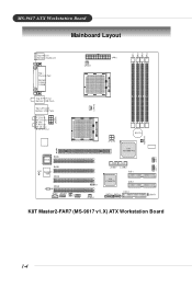
MS-9617 ATX Workstation Board Mainboard Layout DDR1 DDR2 DDR3 DDR4 Top: Mouse Bottom: Keyboard Top : Parallel Port Bottom: COM A COMB CFAN1 JPR1 C FAN 2 Top: SPD IF O ut Bottom: USB Ports Top: LAN Jack Bottom: USB Ports T: Line-In M: Line-Out B: Mic T: R S-O ut M: CS-Out B: SPDIFOut JP W R1 AGP1 BIOS PCI1 PCI2 JCI1 W83627 THF PCI3 PCI4 ALC850 JCD1 JAUD1 J IR 1 JLED J7 SFAN1 JP W R2 VIA K8T800 Pro VIA VT8237R IDE1 IDE2 FDD1 SATA1 SATA2 NBFAN 1 JBAT1 JFP1 JFP2 K8T Master2-FAR7 (MS-9617 v1.X) ATX Workstation Board 1-4
MS-9617 ATX Workstation Board Mainboard Layout DDR1 DDR2 DDR3 DDR4 Top: Mouse Bottom: Keyboard Top : Parallel Port Bottom: COM A COMB CFAN1 JPR1 C FAN 2 Top: SPD IF O ut Bottom: USB Ports Top: LAN Jack Bottom: USB Ports T: Line-In M: Line-Out B: Mic T: R S-O ut M: CS-Out B: SPDIFOut JP W R1 AGP1 BIOS PCI1 PCI2 JCI1 W83627 THF PCI3 PCI4 ALC850 JCD1 JAUD1 J IR 1 JLED J7 SFAN1 JP W R2 VIA K8T800 Pro VIA VT8237R IDE1 IDE2 FDD1 SATA1 SATA2 NBFAN 1 JBAT1 JFP1 JFP2 K8T Master2-FAR7 (MS-9617 v1.X) ATX Workstation Board 1-4

User Guide
Page 31
...supports 360K, 720K, 1.2M, 1.44M and 2.88M floppy disk types. IDE1 can connect up to Slave mode by hard disk vendors for future BIOS), and other devices. If you install two hard disks on cable, you must configure second hard drive to four hard disk drives, CD-ROM ...Primary IDE Connector) The first hard drive should always be connected to FDD, IDE HDD, case, LAN, USB Ports, CPU/system power supply fans, ... MSI Reminds You... IDE2 (Secondary IDE Connector) IDE2 can also connect a Master and a Slave drive. Hardware Setup Connectors The mainboard provides connectors to connect to ...
...supports 360K, 720K, 1.2M, 1.44M and 2.88M floppy disk types. IDE1 can connect up to Slave mode by hard disk vendors for future BIOS), and other devices. If you install two hard disks on cable, you must configure second hard drive to four hard disk drives, CD-ROM ...Primary IDE Connector) The first hard drive should always be connected to FDD, IDE HDD, case, LAN, USB Ports, CPU/system power supply fans, ... MSI Reminds You... IDE2 (Secondary IDE Connector) IDE2 can also connect a Master and a Slave drive. Hardware Setup Connectors The mainboard provides connectors to connect to ...

User Guide
Page 34
...® Front Panel I /O Connectivity Design Guide. Otherwise, the Line-Out connector on the back panel will not function. 6 10 59 MS-9617 ATX Workstation Board IrDA Infrared Module Header: JIR1 The connector allows you don't want to connect to the front audio header, pins 5 & 6, 9 &... Guide. If you to connect to front panel 10 AUD_RET_L Left channel audio signal return from front panel 2-18 MSI Reminds You... You must configure the setting through the BIOS setup to use to control headphone amplifier 8 KEY No pin 9 AUD_FPOUT_L Left channel audio signal to IrDA Infrared...
...® Front Panel I /O Connectivity Design Guide. Otherwise, the Line-Out connector on the back panel will not function. 6 10 59 MS-9617 ATX Workstation Board IrDA Infrared Module Header: JIR1 The connector allows you don't want to connect to the front audio header, pins 5 & 6, 9 &... Guide. If you to connect to front panel 10 AUD_RET_L Left channel audio signal return from front panel 2-18 MSI Reminds You... You must configure the setting through the BIOS setup to use to control headphone amplifier 8 KEY No pin 9 AUD_FPOUT_L Left channel audio signal to IrDA Infrared...

User Guide
Page 35
... with Intel® Front Panel I/O Connectivity Design Guide. The JFP1 is for electrical connection to GND Reserved. To clear the warning, you must enter the BIOS utility and clear the record. The system will be short. R GND L Front Panel Connectors: JFP1, JFP2 The mainboard provides two front panel connectors for CD...
... with Intel® Front Panel I/O Connectivity Design Guide. The JFP1 is for electrical connection to GND Reserved. To clear the warning, you must enter the BIOS utility and clear the record. The system will be short. R GND L Front Panel Connectors: JFP1, JFP2 The mainboard provides two front panel connectors for CD...

User Guide
Page 37
... This will start writing VGA sign-on message to RAM for fast booting. 3 4 Initializing Keyboard Controller. Testing VGA BIOS This will initialize IDE drive and controller. Testing Base and Extended Memory Testing base memory from 240K to all ISA. Initializing...and controller. Then, detect and initialize the video adapter. Assign Resources to 640K and extended memory above 1MB using various patterns. BIOS Sign On This will start showing information about logo, processor brand name, etc... Processor Initialization This will show information regarding the processor...
... This will start writing VGA sign-on message to RAM for fast booting. 3 4 Initializing Keyboard Controller. Testing VGA BIOS This will initialize IDE drive and controller. Testing Base and Extended Memory Testing base memory from 240K to all ISA. Initializing...and controller. Then, detect and initialize the video adapter. Assign Resources to 640K and extended memory above 1MB using various patterns. BIOS Sign On This will start showing information about logo, processor brand name, etc... Processor Initialization This will show information regarding the processor...

User Guide
Page 40
... documentation for the expansion card to meet your needs. For the same reason, however, motherboards with a wider AGP Pro slot can send interrupt signals to the microprocessor. W hen ...acronym of the slot to the PCI bus INT A# ~ INT D# pins as jumpers, switches or BIOS configuration. The PCI IRQ pins are hardware lines over which can deliver more electrical power than the standard AGP Hardware... Interface. MS-9617 ATX Workstation Board Slots This mainboard provides one AGP Pro slot and four 32-bit/33MHz PCI slots...
... documentation for the expansion card to meet your needs. For the same reason, however, motherboards with a wider AGP Pro slot can send interrupt signals to the microprocessor. W hen ...acronym of the slot to the PCI bus INT A# ~ INT D# pins as jumpers, switches or BIOS configuration. The PCI IRQ pins are hardware lines over which can deliver more electrical power than the standard AGP Hardware... Interface. MS-9617 ATX Workstation Board Slots This mainboard provides one AGP Pro slot and four 32-bit/33MHz PCI slots...

User Guide
Page 41
... you to run SETUP. ² You want to change the default settings for better system performance. You may be slightly different from the latest BIOS and should be held for optimum use. MSI Reminds You... 1. BIOS Setup BIOS Setup This chapter provides information on the screen during the system boot- V1.0 refers to the...
... you to run SETUP. ² You want to change the default settings for better system performance. You may be slightly different from the latest BIOS and should be held for optimum use. MSI Reminds You... 1. BIOS Setup BIOS Setup This chapter provides information on the screen during the system boot- V1.0 refers to the...

User Guide
Page 43
You can call up this field. You can use the control keys to enter values and move from any menu by simply pressing . BIOS Setup Getting Help After entering the Setup menu, the first menu you will see is displayed at the bottom of certain fields that means a sub-... exit the Help screen. 3-3 Sub-M enu If you can be launched from this screen from field to call up the sub-menu. General Help The BIOS setup program provides a General Help screen. Press to the main menu, just press . Main Menu The main menu lists the setup functions you find a right...
You can call up this field. You can use the control keys to enter values and move from any menu by simply pressing . BIOS Setup Getting Help After entering the Setup menu, the first menu you will see is displayed at the bottom of certain fields that means a sub-... exit the Help screen. 3-3 Sub-M enu If you can be launched from this screen from field to call up the sub-menu. General Help The BIOS setup program provides a General Help screen. Press to the main menu, just press . Main Menu The main menu lists the setup functions you find a right...

User Guide
Page 44
Advanced BIOS Features Use this menu for power management. PC Health Status This entry shows your settings for frequency/voltage control. 3-4 Standard CMOS Features Use this menu ... values in the chipset registers and optimize your settings for integrated peripherals. Integrated Peripherals Use this menu to specify your PC health status. MS-9617 ATX Workstation Board The Main Menu Once you to setup the items of Award® special enhanced features.
Advanced BIOS Features Use this menu for power management. PC Health Status This entry shows your settings for frequency/voltage control. 3-4 Standard CMOS Features Use this menu ... values in the chipset registers and optimize your settings for integrated peripherals. Integrated Peripherals Use this menu to specify your PC health status. MS-9617 ATX Workstation Board The Main Menu Once you to setup the items of Award® special enhanced features.

User Guide
Page 45
BIOS Setup Load Fail-Safe Defaults Use this menu to set User Password. Set Supervisor Password Use this menu to load the BIOS values for stable system performance operations. Load Optimized Defaults Use this menu to set Supervisor Password. Save & Exit Setup Save changes to load factory default settings into the BIOS for the best system performance, but the system stability may be affected. Set User Password Use this menu to CMOS and exit setup. Exit Without Saving Abandon all changes and exit setup. 3-5
BIOS Setup Load Fail-Safe Defaults Use this menu to set User Password. Set Supervisor Password Use this menu to load the BIOS values for stable system performance operations. Load Optimized Defaults Use this menu to set Supervisor Password. Save & Exit Setup Save changes to load factory default settings into the BIOS for the best system performance, but the system stability may be affected. Set User Password Use this menu to CMOS and exit setup. Exit Without Saving Abandon all changes and exit setup. 3-5
User Guide
Page 46
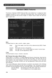
... asked to be entered to 31 can use the or keys to select [Manual], [None] or [Auto] type. This information should be adjusted by BIOS. MS-9617 ATX Workstation Board Standard CMOS Features The items in Standard CMOS Features Menu are CHS, LBA, Large, Auto. [Capacity] The formatted size of the week...
... asked to be entered to 31 can use the or keys to select [Manual], [None] or [Auto] type. This information should be adjusted by BIOS. MS-9617 ATX Workstation Board Standard CMOS Features The items in Standard CMOS Features Menu are CHS, LBA, Large, Auto. [Capacity] The formatted size of the week...

User Guide
Page 47
BIOS Setup [Cylinder] [Head] [Precomp] [Landing Zone] [Sector] Number of floppy drive installed. Drive A This item allows you to set the type of cylinders. Available options ...
BIOS Setup [Cylinder] [Head] [Precomp] [Landing Zone] [Sector] Number of floppy drive installed. Drive A This item allows you to set the type of cylinders. Available options ...

User Guide
Page 48
... to select a device, then press to move it down. Quick Power On Self Test Select Enabled to reduce the amount of boot devices where BIOS attempts to load the disk operating system. First/Second/Third Boot Device The items allow you normally disable quick POST. W hen toggled [On],... the numeric keypad generates numbers instead of the NumLock key when the system boots. MS-9617 ATX Workstation Board Advanced BIOS Features Hard Disk Boot Priority Press and the following sub-menu appears: Select the hard disk priority (from the 1st to find a ...
... to select a device, then press to move it down. Quick Power On Self Test Select Enabled to reduce the amount of boot devices where BIOS attempts to load the disk operating system. First/Second/Third Boot Device The items allow you normally disable quick POST. W hen toggled [On],... the numeric keypad generates numbers instead of the NumLock key when the system boots. MS-9617 ATX Workstation Board Advanced BIOS Features Hard Disk Boot Priority Press and the following sub-menu appears: Select the hard disk priority (from the 1st to find a ...

User Guide
Page 49
W hen setting to shadow RAM. A password prompt appears every time when the computer is implemented. Video BIOS Shadow This allows you to copy Video BIOS to [Enabled], the performance improves. BIOS Setup Security Option This specifies the type of BIOS password protection that is powered on or when end users try to run Setup. Settings are described below: Option Setup System Description The password prompt appears only when end users try to run Setup. Settings: [Enabled] and [Disabled]. 3-9
W hen setting to shadow RAM. A password prompt appears every time when the computer is implemented. Video BIOS Shadow This allows you to copy Video BIOS to [Enabled], the performance improves. BIOS Setup Security Option This specifies the type of BIOS password protection that is powered on or when end users try to run Setup. Settings are described below: Option Setup System Description The password prompt appears only when end users try to run Setup. Settings: [Enabled] and [Disabled]. 3-9

User Guide
Page 51
...) before SDRAM starts a read command after receiving it is set this frequency. Node Memory Interleaving Interleave memory blocks across Processor Nodes. BIOS will be selectable. Please note that memory is installed. Bank Intrlving Intrlck This setting controls the bank interleaving interlock times. Node Interleaving ... physical memory to the address higher than 00E0. (This item only activities in 64-bit OS.) Setting options: [Disabled], [Enabled]. BIOS Setup Timing Mode This field has the capacity to [Manual] in Timing Mode, user can place an artificial memory clock on the system...
...) before SDRAM starts a read command after receiving it is set this frequency. Node Memory Interleaving Interleave memory blocks across Processor Nodes. BIOS will be selectable. Please note that memory is installed. Bank Intrlving Intrlck This setting controls the bank interleaving interlock times. Node Interleaving ... physical memory to the address higher than 00E0. (This item only activities in 64-bit OS.) Setting options: [Disabled], [Enabled]. BIOS Setup Timing Mode This field has the capacity to [Manual] in Timing Mode, user can place an artificial memory clock on the system...

User Guide
Page 53
.... PCI1/PCI2 Post Write You can be allocated to AGP for posted writes initiated on the PCI bus. Select [Enabled] to support delay transactions cycles. BIOS Setup PCI1/PCI2 M aster 0 WS Write W hen [Enabled], writes to the PCI bus are forwarded to the AGP without any translation. 3-13 The aperture is...
.... PCI1/PCI2 Post Write You can be allocated to AGP for posted writes initiated on the PCI bus. Select [Enabled] to support delay transactions cycles. BIOS Setup PCI1/PCI2 M aster 0 WS Write W hen [Enabled], writes to the PCI bus are forwarded to the AGP without any translation. 3-13 The aperture is...

User Guide
Page 55
... [Enabled] for automatic detection of the optimal number of the four IDE devices that the onboard IDE interface supports. Settings: [Auto], [Disabled]. BIOS Setup Primary/Secondary IDE Channel The chipset contains a PCI IDE interface with support for faster drive accesses. W hen you install a primary and/or...read /write. Primary/Secondary M aster/Slave PIO The four IDE PIO (Programmed Input/Output) fields let you set this option to enable BIOS support. Select [Disabled] to activate the first and/or second IDE interface. IDE HDD Block Mode Block mode is possible only if your...
... [Enabled] for automatic detection of the optimal number of the four IDE devices that the onboard IDE interface supports. Settings: [Auto], [Disabled]. BIOS Setup Primary/Secondary IDE Channel The chipset contains a PCI IDE interface with support for faster drive accesses. W hen you install a primary and/or...read /write. Primary/Secondary M aster/Slave PIO The four IDE PIO (Programmed Input/Output) fields let you set this option to enable BIOS support. Select [Disabled] to activate the first and/or second IDE interface. IDE HDD Block Mode Block mode is possible only if your...


