
User Guide
Page 4
... the voltage of the following help resources for further guidance. † Visit the MSI homepage & FAQ site for technical guide, BIOS updates, driver updates, and other information: http://www.msi.com.tw & http://www.msi. All cautions and warnings on the enclosure are for future reference. 3. CAUTION:... equipment has obvious sign of breakage. 12. com.tw/program/service/faq/faq/esc_faq_list.php † Contact our technical staff at: support@msi.com.tw Safety Instructions 1. Do not leave this equipment away from humidity. 4. Technical Support If a problem arises with the same or ...
... the voltage of the following help resources for further guidance. † Visit the MSI homepage & FAQ site for technical guide, BIOS updates, driver updates, and other information: http://www.msi.com.tw & http://www.msi. All cautions and warnings on the enclosure are for future reference. 3. CAUTION:... equipment has obvious sign of breakage. 12. com.tw/program/service/faq/faq/esc_faq_list.php † Contact our technical staff at: support@msi.com.tw Safety Instructions 1. Do not leave this equipment away from humidity. 4. Technical Support If a problem arises with the same or ...
User Guide
Page 6
... Chipset Features 3-11 Integrated Peripherals 3-12 Power Management Setup 3-17 PNP/PCI Configurations 3-20 H/W Monitor ...3-22 Cell Menu ...3-23 Load Fail-Safe/Optimized Defaults 3-30 BIOS Setting Password 3-31 Chapter 4. Introduction to DigiCell 4-1 Main ...4-2 H/W Diagnostic ...4-4 Communication ...4-5 Software Access Point 4-6 Terminology 4-6 Access Point Mode 4-7 WLAN Card Mode 4-8 Live Update ...4-9 MEGA STICK ...4-10...
... Chipset Features 3-11 Integrated Peripherals 3-12 Power Management Setup 3-17 PNP/PCI Configurations 3-20 H/W Monitor ...3-22 Cell Menu ...3-23 Load Fail-Safe/Optimized Defaults 3-30 BIOS Setting Password 3-31 Chapter 4. Introduction to DigiCell 4-1 Main ...4-2 H/W Diagnostic ...4-4 Communication ...4-5 Software Access Point 4-6 Terminology 4-6 Access Point Mode 4-7 WLAN Card Mode 4-8 Live Update ...4-9 MEGA STICK ...4-10...

User Guide
Page 7
... 4-18 Power Off / Restart 4-19 Start W ith ...4-19 Auto Login 4-20 Chapter 5. Installation of RAID Configurations 5-2 RAID Configuration 5-3 Basic Configuration Instructions 5-3 Setting Up the NVRAID BIOS 5-3 NVIDIA RAID Untility Installation 5-7 Installing the RAID Driver (for bootable RAID Array 5-7 Installing the NVIDIA RAID Software Under W indows (for Non-bootable RAID Array 5-9 Initializing...
... 4-18 Power Off / Restart 4-19 Start W ith ...4-19 Auto Login 4-20 Chapter 5. Installation of RAID Configurations 5-2 RAID Configuration 5-3 Basic Configuration Instructions 5-3 Setting Up the NVRAID BIOS 5-3 NVIDIA RAID Untility Installation 5-7 Installing the RAID Driver (for bootable RAID Array 5-7 Installing the NVIDIA RAID Software Under W indows (for Non-bootable RAID Array 5-9 Initializing...
User Guide
Page 11
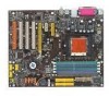
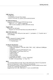
... SPDIF out - 1 coaxial SPDIF out - 1 IrDA pinheader - 1 CD-In pinheader - 1 D-Bracket2 pinheader - 2 IEEE1394 ports (Rear * 1 / Front * 1)(Optional) - 10 USB1.1/2.0 ports (Rear * 4 / Front * 6) BIOS † The mainboard BIOS provides "Plug & Play" BIOS which detects the peripheral devices and expansion cards of the board automatically. † The mainboard provides a Desktop Management Interface (DMI) function which...
... SPDIF out - 1 coaxial SPDIF out - 1 IrDA pinheader - 1 CD-In pinheader - 1 D-Bracket2 pinheader - 2 IEEE1394 ports (Rear * 1 / Front * 1)(Optional) - 10 USB1.1/2.0 ports (Rear * 4 / Front * 6) BIOS † The mainboard BIOS provides "Plug & Play" BIOS which detects the peripheral devices and expansion cards of the board automatically. † The mainboard provides a Desktop Management Interface (DMI) function which...
User Guide
Page 31
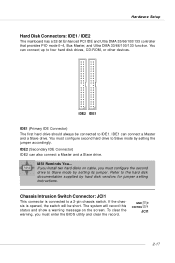
You must configure second hard drive to the hard disk documentation supplied by hard disk vendors for jumper setting instructions. MSI Reminds You... Refer to Slave mode by setting its jumper. If you install two hard disks on the screen. Chassis Intrusion Switch Connector: JCI1 This .../100/133 controller that provides PIO mode 0~4, Bus Master, and Ultra DMA 33/66/100/133 function. To clear the warning, you must enter the BIOS utility and clear the record.
You must configure second hard drive to the hard disk documentation supplied by hard disk vendors for jumper setting instructions. MSI Reminds You... Refer to Slave mode by setting its jumper. If you install two hard disks on the screen. Chassis Intrusion Switch Connector: JCI1 This .../100/133 controller that provides PIO mode 0~4, Bus Master, and Ultra DMA 33/66/100/133 function. To clear the warning, you must enter the BIOS utility and clear the record.

User Guide
Page 34
...174; Front Panel I /O Connectivity Design Guide. You must configure the setting through the BIOS setup to use to control headphone amplifier No pin Left channel audio signal to front panel Left... channel audio signal return from front panel MSI Reminds You... If you to connect to IrDA Infrared module. Otherwise, the Line-Out ...10 have to be jumpered in order to have signal output directed to the rear audio ports. M S-7125 ATX M ainboard Front Panel Audio Connector: JAUD1 The JAUD1 front panel audio connector allows you to connect to the...
...174; Front Panel I /O Connectivity Design Guide. You must configure the setting through the BIOS setup to use to control headphone amplifier No pin Left channel audio signal to front panel Left... channel audio signal return from front panel MSI Reminds You... If you to connect to IrDA Infrared module. Otherwise, the Line-Out ...10 have to be jumpered in order to have signal output directed to the rear audio ports. M S-7125 ATX M ainboard Front Panel Audio Connector: JAUD1 The JAUD1 front panel audio connector allows you to connect to the...
User Guide
Page 37
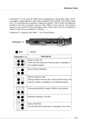
...Setup D-Bracket™ 2 is damaged or not installed properly. Early Chipset Initialization Memory Detection Test Testing onboard memory size. Testing VGA BIOS This will hang here if the processor is very useful for fast booting. This special feature is damaged or 3 4 not installed ... module is an external USB bracket integrating four Diagnostic LEDs, which use the feature to debug the system. Initializing Keyboard Controller. Decompressing BIOS image to help users understand their system. D-Bracket™ 2 supports both USB 1.1 & 2.0 specification. The 4 LEDs can use...
...Setup D-Bracket™ 2 is damaged or not installed properly. Early Chipset Initialization Memory Detection Test Testing onboard memory size. Testing VGA BIOS This will hang here if the processor is very useful for fast booting. This special feature is damaged or 3 4 not installed ... module is an external USB bracket integrating four Diagnostic LEDs, which use the feature to debug the system. Initializing Keyboard Controller. Decompressing BIOS image to help users understand their system. D-Bracket™ 2 supports both USB 1.1 & 2.0 specification. The 4 LEDs can use...
User Guide
Page 38
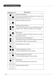
Assign Resources to 640K and extended memory above 1MB using various patterns. Operating System Booting 2-24 BIOS Sign On This will start detecting CPU clock, checking type of video onboard. Initializing Floppy Drive Controller This will... video adapter. Testing Base and Extended Memory Testing base memory from 240K to all ISA. Boot Attempt This will initialize Floppy Drive and controller. M S-7125 ATX M ainboard D-Bracket™ 2 Description Processor Initialization 1 2 This will show information regarding the processor (like 3 4 brand name, system bus, etc...) ...
Assign Resources to 640K and extended memory above 1MB using various patterns. Operating System Booting 2-24 BIOS Sign On This will start detecting CPU clock, checking type of video onboard. Initializing Floppy Drive Controller This will... video adapter. Testing Base and Extended Memory Testing base memory from 240K to all ISA. Boot Attempt This will initialize Floppy Drive and controller. M S-7125 ATX M ainboard D-Bracket™ 2 Description Processor Initialization 1 2 This will show information regarding the processor (like 3 4 brand name, system bus, etc...) ...
User Guide
Page 40
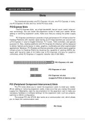
M S-7125 ATX M ainboard Slots The mainboard provides one PCI Express x16 slot, one PCI Express x1 slots, one PCI Express x4 slots and four 32-bit PCI bus slots. PCI Express Slots The PCI Express slots, as jumpers, switches or BIOS configuration. Also, desktop platforms with transfer rates starting at 2.5 Giga transfers per...
M S-7125 ATX M ainboard Slots The mainboard provides one PCI Express x16 slot, one PCI Express x1 slots, one PCI Express x4 slots and four 32-bit PCI bus slots. PCI Express Slots The PCI Express slots, as jumpers, switches or BIOS configuration. Also, desktop platforms with transfer rates starting at 2.5 Giga transfers per...
User Guide
Page 42
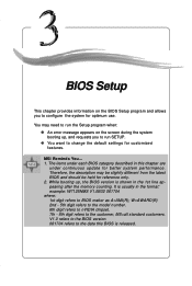
...number. 6th digit refers to nVIDIA chipset. 7th - 8th digit refers to BIOS maker as A=AMI(R); V1.0 refers to the BIOS version. 061704 refers to change the default settings for better system performance. BIOS Setup BIOS Setup This chapter provides information on the screen during the system booting up ,... run SETUP. ” You want to the date this chapter are under continuous update for customized features. MSI Reminds You... 1. The items under each BIOS category described in this BIOS is shown in the format: example: W7125NMS V1.0B32 061704 where: 1st digit refers to the customer, ...
...number. 6th digit refers to nVIDIA chipset. 7th - 8th digit refers to BIOS maker as A=AMI(R); V1.0 refers to the BIOS version. 061704 refers to change the default settings for better system performance. BIOS Setup BIOS Setup This chapter provides information on the screen during the system booting up ,... run SETUP. ” You want to the date this chapter are under continuous update for customized features. MSI Reminds You... 1. The items under each BIOS category described in this BIOS is shown in the format: example: W7125NMS V1.0B32 061704 where: 1st digit refers to the customer, ...
User Guide
Page 43
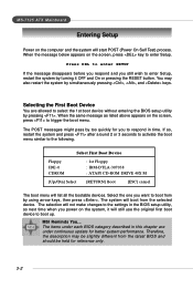
...selection will not make changes to the settings in this chapter are allowed to respond in time. MSI Reminds You... When the same message as listed above appears on the screen, press to enter ... items under continuous update for better system performance. You may be slightly different from the latest BIOS and should be held for you power on the system, it OFF and On or pressing ... to activate the boot menu similar to enter Setup, restart the system by pressing . MS-7125 ATX Mainboard Entering Setup Power on the computer and the system will list all the bootable devices. Press ...
...selection will not make changes to the settings in this chapter are allowed to respond in time. MSI Reminds You... When the same message as listed above appears on the screen, press to enter ... items under continuous update for better system performance. You may be slightly different from the latest BIOS and should be held for you power on the system, it OFF and On or pressing ... to activate the boot menu similar to enter Setup, restart the system by pressing . MS-7125 ATX Mainboard Entering Setup Power on the computer and the system will list all the bootable devices. Press ...
User Guide
Page 44
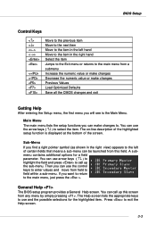
... in the left of certain fields that means a sub-menu can use the arrow keys ( ↑↓ ) to select the item. General Help The BIOS setup program provides a General Help screen. Press to the main menu, just press the . A submenu contains additional options for the highlighted item. Then you ... press to call up the sub-menu. You can call up this field. You can use and the possible selections for a field parameter. BIOS Setup Control Keys Enter> Move to the previous item Move to the next item Move to the item in the right hand Select the item...
... in the left of certain fields that means a sub-menu can use the arrow keys ( ↑↓ ) to select the item. General Help The BIOS setup program provides a General Help screen. Press to the main menu, just press the . A submenu contains additional options for the highlighted item. Then you ... press to call up the sub-menu. You can call up this field. You can use and the possible selections for a field parameter. BIOS Setup Control Keys Enter> Move to the previous item Move to the next item Move to the item in the right hand Select the item...

User Guide
Page 45
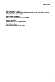
... date etc. Power Management Setup Use this menu to specify your settings for power management. The Main Menu allows you enter Phoenix-Award® BIOS CMOS Setup Utility, the Main Menu will appear on the screen. Cell Menu Use this menu to specify your system's performance. Advanced...to specify your system supports PnP/PCI. Advanced Chipset Features Use this menu to setup the items of AWARD® special enhanced features. MS-7125 ATX Mainboard The Main Menu Once you to select from twelve setup functions and two exit choices. H/W Monitor Use this menu for CPU/AGP frequency/...
... date etc. Power Management Setup Use this menu to specify your settings for power management. The Main Menu allows you enter Phoenix-Award® BIOS CMOS Setup Utility, the Main Menu will appear on the screen. Cell Menu Use this menu to specify your system's performance. Advanced...to specify your system supports PnP/PCI. Advanced Chipset Features Use this menu to setup the items of AWARD® special enhanced features. MS-7125 ATX Mainboard The Main Menu Once you to select from twelve setup functions and two exit choices. H/W Monitor Use this menu for CPU/AGP frequency/...
User Guide
Page 46
Save & Exit Setup Save changes to load the BIOS values for BIOS. BIOS Setup Load Optimized Defaults Use this menu to set the password for the best system performance, but the system stability may be affected. Exit Without Saving Abandon all changes and exit setup. 3-5 BIOS Setting Password Use this menu to CMOS and exit setup.
Save & Exit Setup Save changes to load the BIOS values for BIOS. BIOS Setup Load Optimized Defaults Use this menu to set the password for the best system performance, but the system stability may be affected. Exit Without Saving Abandon all changes and exit setup. 3-5 BIOS Setting Password Use this menu to CMOS and exit setup.
User Guide
Page 47
.../Secondary Master/Slave Press PgUp/ or PgDn/ to set the system time that the specifications of the week, from Sun to be adjusted by BIOS. Capacity The formatted size of cylinders. 3-6 The format is . The hard disk will not work properly if you want in the documentation from... 1 to 31 can be entered to the following items. Enter the information directly from Jan. MS-7125 ATX Mainboard Standard CMOS Features The items in Standard CMOS Features Menu includes some basic setup items. Use the arrow keys to highlight the item...
.../Secondary Master/Slave Press PgUp/ or PgDn/ to set the system time that the specifications of the week, from Sun to be adjusted by BIOS. Capacity The formatted size of cylinders. 3-6 The format is . The hard disk will not work properly if you want in the documentation from... 1 to 31 can be entered to the following items. Enter the information directly from Jan. MS-7125 ATX Mainboard Standard CMOS Features The items in Standard CMOS Features Menu includes some basic setup items. Use the arrow keys to highlight the item...
User Guide
Page 48
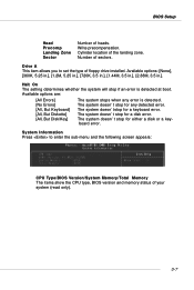
...sectors. Drive A This item allows you to enter the sub-menu and the following screen appears: CPU Type/BIOS Version/System Memory/Total Memory The items show the CPU type, BIOS version and memory status of your system (read only). 3-7 Available options are: [All Errors] [No .... The system doesn'tstop for any error is detected at boot. System Information Press to set the type of heads. Number of the landing zone. BIOS Setup Head Precomp Landing Zone Sector Number of floppy drive installed. Available options: [None], [360K, 5.25 in.], [1.2M, 5.25 in.], [720K, 3.5...
...sectors. Drive A This item allows you to enter the sub-menu and the following screen appears: CPU Type/BIOS Version/System Memory/Total Memory The items show the CPU type, BIOS version and memory status of your system (read only). 3-7 Available options are: [All Errors] [No .... The system doesn'tstop for any error is detected at boot. System Information Press to set the type of heads. Number of the landing zone. BIOS Setup Head Precomp Landing Zone Sector Number of floppy drive installed. Available options: [None], [360K, 5.25 in.], [1.2M, 5.25 in.], [720K, 3.5...
User Guide
Page 49
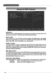
... This item enables you to show the company logo on the full screen at boot. [Disabled] Shows the POST messages at boot. 3-8 MS-7125 ATX Mainboard Advanced BIOS Features Quick Boot Setting the item to [Enabled] allows the system to boot within 5 seconds since it is possible if you choose [Yes]. IOAPIC...
... This item enables you to show the company logo on the full screen at boot. [Disabled] Shows the POST messages at boot. 3-8 MS-7125 ATX Mainboard Advanced BIOS Features Quick Boot Setting the item to [Enabled] allows the system to boot within 5 seconds since it is possible if you choose [Yes]. IOAPIC...
User Guide
Page 50
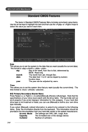
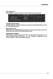
... Device Setting the option to [Enabled] allows the system to try to boot from other device if the system fails to enter the sub-menu. BIOS Setup Boot Sequence Press to enter the sub-menu and the following screen appears: 1st/2nd/3rd Boot Device The items allow you may use...; ) to select the desired device, then press , or , key to load the disk operating system. Then you to set the sequence of boot devices where BIOS attempts to move it up/down in this hard disk boot priority list. 3-9
... Device Setting the option to [Enabled] allows the system to try to boot from other device if the system fails to enter the sub-menu. BIOS Setup Boot Sequence Press to enter the sub-menu and the following screen appears: 1st/2nd/3rd Boot Device The items allow you may use...; ) to select the desired device, then press , or , key to load the disk operating system. Then you to set the sequence of boot devices where BIOS attempts to move it up/down in this hard disk boot priority list. 3-9
User Guide
Page 52
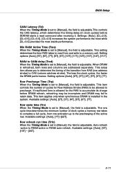
... row activation up to the precharging of cycles for the RAS to accumulate its charge before SDRAM starts a read from and write to a memory cell. BIOS Setup CAS# Latency (Tcl) When the Timing Mode is set to [Manual], the field is adjustable.This controls the CAS latency, which determines the timing...
... row activation up to the precharging of cycles for the RAS to accumulate its charge before SDRAM starts a read from and write to a memory cell. BIOS Setup CAS# Latency (Tcl) When the Timing Mode is set to [Manual], the field is adjustable.This controls the CAS latency, which determines the timing...
User Guide
Page 54
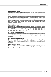
... and then enable its DQS receiver until the read . Async Latency value When the User Config mode is set to [Manual], the field is adjustable. BIOS Setup Read Preamble value When the User Config mode is set to [Manual], the field is adjustable. The controller will disable its DQS receiver while...
... and then enable its DQS receiver until the read . Async Latency value When the User Config mode is set to [Manual], the field is adjustable. BIOS Setup Read Preamble value When the User Config mode is set to [Manual], the field is adjustable. The controller will disable its DQS receiver while...


