User Guide
Page 2
...174; and Pentium® are registered trademarks of AMD Corporation. Award® is a registered trademark of Microsoft Corporation. Visit the MSI website for further guidance. Trademarks All trademarks are registered trademarks of Novell, Inc. W indows® 95/98/2000/NT/XP are...msi.com.tw ii Revision History Revision v2.3 Revision History First release Date December 2006 Technical Support If a problem arises with your system and no guarantee is given as to make changes without notice. Alternatively, please try the following help resources for FAQ, technical guide, BIOS...
...174; and Pentium® are registered trademarks of AMD Corporation. Award® is a registered trademark of Microsoft Corporation. Visit the MSI website for further guidance. Trademarks All trademarks are registered trademarks of Novell, Inc. W indows® 95/98/2000/NT/XP are...msi.com.tw ii Revision History Revision v2.3 Revision History First release Date December 2006 Technical Support If a problem arises with your system and no guarantee is given as to make changes without notice. Alternatively, please try the following help resources for FAQ, technical guide, BIOS...

User Guide
Page 9
Front USB Connectors: JUSB1~JUSB2 2-18 Front Panel Audio Connector: JAUD1 2-18 Chassis Intrusion Switch Connector: JCI1 2-19 SPDIF-Out Connector: JSPD1 2-19 Jumpers ...2-20 Clear CMOS Jumper: JBAT1 2-20 Slots ...2-21 PCI Express Slots 2-21 PCI (Peripheral Component Interconnect) Slots 2-21 PCI Interrupt Request Routing 2-21 Chapter 3. BIOS Setup 3-1 Entering Setup ...3-2 Control Keys 3-3 Getting Help 3-3 General Help
Front USB Connectors: JUSB1~JUSB2 2-18 Front Panel Audio Connector: JAUD1 2-18 Chassis Intrusion Switch Connector: JCI1 2-19 SPDIF-Out Connector: JSPD1 2-19 Jumpers ...2-20 Clear CMOS Jumper: JBAT1 2-20 Slots ...2-21 PCI Express Slots 2-21 PCI (Peripheral Component Interconnect) Slots 2-21 PCI Interrupt Request Routing 2-21 Chapter 3. BIOS Setup 3-1 Entering Setup ...3-2 Control Keys 3-3 Getting Help 3-3 General Help
User Guide
Page 19
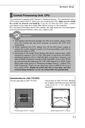
... CPU cooler, contact your dealer to the Intel® North Bridge 945-family chipset spec, 945P mainboard supports CPU of FSB 1066 MHz at maximum and 945PL mainboard supports CPU of LGA 775.../Voltage Control] -> [Adjust CPU FSB Frequency]. While replacing the CPU, always turn off the ATX power supply or unplug the power supply's power cord from overheating. 2. Remember to apply some silicone...computer. (For the latest information about CPU, please visit http://www.msi.com.tw/program/ p ro du c t s / ma in BIOS: Enter BIOS setup menu and go to ensure the safety of LGA 775 CPU....
... CPU cooler, contact your dealer to the Intel® North Bridge 945-family chipset spec, 945P mainboard supports CPU of FSB 1066 MHz at maximum and 945PL mainboard supports CPU of LGA 775.../Voltage Control] -> [Adjust CPU FSB Frequency]. While replacing the CPU, always turn off the ATX power supply or unplug the power supply's power cord from overheating. 2. Remember to apply some silicone...computer. (For the latest information about CPU, please visit http://www.msi.com.tw/program/ p ro du c t s / ma in BIOS: Enter BIOS setup menu and go to ensure the safety of LGA 775 CPU....

User Guide
Page 22
... to fasten the cooler. locking switch Important 1. Whenever CPU is not installed, always protect your CPU socket pin with the plastic cap covered (shown in BIOS (Chapter 3) for the CPU temperature. 2. MS-7236 Mainboard 9. Align the holes on it) to lock the h ook s . 12. Push down the load lever lightly onto...
... to fasten the cooler. locking switch Important 1. Whenever CPU is not installed, always protect your CPU socket pin with the plastic cap covered (shown in BIOS (Chapter 3) for the CPU temperature. 2. MS-7236 Mainboard 9. Align the holes on it) to lock the h ook s . 12. Push down the load lever lightly onto...

User Guide
Page 35
If the chassis is opened, the switch will record this status and show a warning message on the screen. To clear the warning, you must enter the BIOS utility and clear the record. Hardware Setup Chassis Intrusion Switch Connector: JCI1 This connector is connected to the HDMI graphics card. The system will be short. CINTRU 1 GNF 2 JCI1 SPDIF-Out Connector: JSPD1 (Optional, for HDMI graphics card only) This connector is used to connect SPDIF (Sony & Philips Digital Interconnect Format) interface for digital audio transmission to a 2-pin chassis switch. SPDF0 GND JSPD1 2-19
If the chassis is opened, the switch will record this status and show a warning message on the screen. To clear the warning, you must enter the BIOS utility and clear the record. Hardware Setup Chassis Intrusion Switch Connector: JCI1 This connector is connected to the HDMI graphics card. The system will be short. CINTRU 1 GNF 2 JCI1 SPDIF-Out Connector: JSPD1 (Optional, for HDMI graphics card only) This connector is used to connect SPDIF (Sony & Philips Digital Interconnect Format) interface for digital audio transmission to a 2-pin chassis switch. SPDF0 GND JSPD1 2-19

User Guide
Page 37
... The IRQ, acronym of 4.0 GB/s over a PCI Express x1 lane for the expansion card to the PCI bus INT A# ~ INT D# pins as jumpers, switches or BIOS configuration. Hardware Setup Slots The mainboard provides one PCI Express x16 slot, two PCI Express x1 slots and three 32-bit PCI bus slots. PCI...
... The IRQ, acronym of 4.0 GB/s over a PCI Express x1 lane for the expansion card to the PCI bus INT A# ~ INT D# pins as jumpers, switches or BIOS configuration. Hardware Setup Slots The mainboard provides one PCI Express x16 slot, two PCI Express x1 slots and three 32-bit PCI bus slots. PCI...

User Guide
Page 38
You want to change the default settings for optimum use. You may need to run the Setup program when: An error message appears on the BIOS Setup program and allows you to run SETUP. ized features. 3-1 Chapter 3 BIOS Setup BIOS Setup This chapter provides the information on the screen during the system booting up, and requests you to configure the system for custom-
You want to change the default settings for optimum use. You may need to run the Setup program when: An error message appears on the BIOS Setup program and allows you to run SETUP. ized features. 3-1 Chapter 3 BIOS Setup BIOS Setup This chapter provides the information on the screen during the system booting up, and requests you to configure the system for custom-
User Guide
Page 39
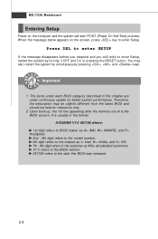
...6th digit refers to the chipset as MS= all standard customers. You may be slightly different from the latest BIOS and should be held for better system performance. oIt ristaunstually in this BIOS was released. 3-2 MS-7236 Mainboard Entering Setup Power on the screen, press key to the customer as ...I= Intel, N= nVidia, and V= VIA. 7th - 8th digit refers to enter Setup. V7.0 refers to the BIOS version. 061109 refers to enter Setup, restart the system by simultaneously pressing , , and keys. W hen the message below appears on the computer and the...
...6th digit refers to the chipset as MS= all standard customers. You may be slightly different from the latest BIOS and should be held for better system performance. oIt ristaunstually in this BIOS was released. 3-2 MS-7236 Mainboard Entering Setup Power on the screen, press key to the customer as ...I= Intel, N= nVidia, and V= VIA. 7th - 8th digit refers to enter Setup. V7.0 refers to the BIOS version. 061109 refers to enter Setup, restart the system by simultaneously pressing , , and keys. W hen the message below appears on the computer and the...

User Guide
Page 40
...values and move from any menu by simply pressing . The on-line description of the highlighted setup function is the Main Menu. General Help The BIOS setup program provides a General Help screen. A sub-menu contains additional options for the highlighted item. Then you will see is displayed at the bottom... of the screen. You can call up this field. Press to . BIOS Setup Control Keys Enter> Move to the previous item Move to the next item Move to the item in the left hand Move to the...
...values and move from any menu by simply pressing . The on-line description of the highlighted setup function is the Main Menu. General Help The BIOS setup program provides a General Help screen. A sub-menu contains additional options for the highlighted item. Then you will see is displayed at the bottom... of the screen. You can call up this field. Press to . BIOS Setup Control Keys Enter> Move to the previous item Move to the next item Move to the item in the left hand Move to the...
User Guide
Page 41
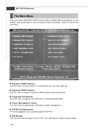
... status. 3-4 Use arrow keys to move among the items and press to specify your settings for basic system configurations, such as time, date etc. Advanced BIOS Features Use this menu to setup the items of your system supports PnP/PCI. PnP/PCI Configurations This entry appears if your CPU, fan, warning... menu for integrated peripherals. Standard CMOS Features Use this menu to enter the sub-menu. MS-7236 Mainboard The Main Menu Once you enter AMI BIOS CMOS Setup Utility, the Main Menu will appear on the screen.
... status. 3-4 Use arrow keys to move among the items and press to specify your settings for basic system configurations, such as time, date etc. Advanced BIOS Features Use this menu to setup the items of your system supports PnP/PCI. PnP/PCI Configurations This entry appears if your CPU, fan, warning... menu for integrated peripherals. Standard CMOS Features Use this menu to enter the sub-menu. MS-7236 Mainboard The Main Menu Once you enter AMI BIOS CMOS Setup Utility, the Main Menu will appear on the screen.

User Guide
Page 42
Load Fail-Safe Defaults Use this menu to load the default values set by the mainboard manufacturer specifically for stable system performance. Save & Exit Setup Save changes to load the default values set the passwords for frequency/ voltage control. BIOS Setup Frequency/Voltage Control Use this menu to specify your settings for BIOS. BIOS Setting Password Use these two menus to set by the BIOS vendor for optimal performance of the mainboard. Exit Without Saving Abandon all changes and exit setup. 3-5 Load Optimized Defaults Use this menu to CMOS and exit setup.
Load Fail-Safe Defaults Use this menu to load the default values set by the mainboard manufacturer specifically for stable system performance. Save & Exit Setup Save changes to load the default values set the passwords for frequency/ voltage control. BIOS Setup Frequency/Voltage Control Use this menu to specify your settings for BIOS. BIOS Setting Password Use these two menus to set by the BIOS vendor for optimal performance of the mainboard. Exit Without Saving Abandon all changes and exit setup. 3-5 Load Optimized Defaults Use this menu to CMOS and exit setup.
User Guide
Page 43
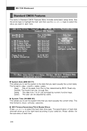
... the current time). Read only. [month] The month from 1 to 31 can be keyed by numeric function keys. [year] The year can be adjusted by BIOS. System Time (HH:M M:SS) This allows you to set the system to the date that you want (usually the current date). The format is . The...
... the current time). Read only. [month] The month from 1 to 31 can be keyed by numeric function keys. [year] The year can be adjusted by BIOS. System Time (HH:M M:SS) This allows you to set the system to the date that you want (usually the current date). The format is . The...

User Guide
Page 44
Available options: [Disabled], [360 KB, 51/4], [1.2 MB, 51/4], [720 KB, 3 1/2], [1.44 MB, 3 1/2], [2.88MB, 3 1/2]. Physical Memory This item shows the physical memory of your system (read only). 3-7 System Information Press to set the type of your system (read only). BIOS Version, Build Date These items show the CPU related information of the floppy drives installed. BIOS Setup Floppy Drive A This item allows you to for the sub-menu of each item: CPU Type, CPU ID, CPU Frequency These items show the BIOS related information of your system (read only).
Available options: [Disabled], [360 KB, 51/4], [1.2 MB, 51/4], [720 KB, 3 1/2], [1.44 MB, 3 1/2], [2.88MB, 3 1/2]. Physical Memory This item shows the physical memory of your system (read only). 3-7 System Information Press to set the type of your system (read only). BIOS Version, Build Date These items show the CPU related information of the floppy drives installed. BIOS Setup Floppy Drive A This item allows you to for the sub-menu of each item: CPU Type, CPU ID, CPU Frequency These items show the BIOS related information of your system (read only).
User Guide
Page 45
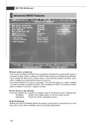
... 5 seconds since it will skip some check items. Available options: [Enabled], [Disabled]. 3-8 The only time when you need to update the BIOS with a Flash utility. You should immedi- Quick Booting Setting the item to [Enabled] allows the system to protect it is when you should ...Enabled] Shows a still image (logo) on the bootup screen. W hen enabled, the BIOS' data cannot be changed when attempting to disable this function at boot. To successfully update the BIOS, you to update the BIOS. Full Screen Logo Display This item enables you 'll need to disable it against viruses...
... 5 seconds since it will skip some check items. Available options: [Enabled], [Disabled]. 3-8 The only time when you need to update the BIOS with a Flash utility. You should immedi- Quick Booting Setting the item to [Enabled] allows the system to protect it is when you should ...Enabled] Shows a still image (logo) on the bootup screen. W hen enabled, the BIOS' data cannot be changed when attempting to disable this function at boot. To successfully update the BIOS, you to update the BIOS. Full Screen Logo Display This item enables you 'll need to disable it against viruses...

User Guide
Page 46
... select the MPS version supported by your operating system. Setting options: [Enabled], [Disabled]. Setting to [Off] will expand available IRQ resources for the operating system. BIOS Setup Boot up Num-Lock LED This setting is to set the Num Lock status when the system is powered on IA -32 s ys tem s .
... select the MPS version supported by your operating system. Setting options: [Enabled], [Disabled]. Setting to [Off] will expand available IRQ resources for the operating system. BIOS Setup Boot up Num-Lock LED This setting is to set the Num Lock status when the system is powered on IA -32 s ys tem s .
User Guide
Page 47
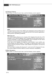
... ensure maximum compatibility. W hen [Disabled], the PCI Express X16 slot will be allowed to run in your system, you should enable this BIOS feature. If you have a PCI Express X16 graphics card installed in its normal PCI Express X16 mode. MS-7236 Mainboard Chipset Feature Press to... following screen appears: HPET The High Precision Event Timer (HPET) was developed by ensuring maximum transfer rates between the graphics card and the motherboard. When [Enabled], the PCI Express X16 slot will be forced to run in the PCI Express X1 mode. Setting options: [Enabled], [Disabled].
... ensure maximum compatibility. W hen [Disabled], the PCI Express X16 slot will be allowed to run in your system, you should enable this BIOS feature. If you have a PCI Express X16 graphics card installed in its normal PCI Express X16 mode. MS-7236 Mainboard Chipset Feature Press to... following screen appears: HPET The High Precision Event Timer (HPET) was developed by ensuring maximum transfer rates between the graphics card and the motherboard. When [Enabled], the PCI Express X16 slot will be forced to run in the PCI Express X1 mode. Setting options: [Enabled], [Disabled].

User Guide
Page 48
However, modern computers usually load the operating system from the hard drive, and may even load it from drive A (floppy disk), so IBM PC-compatible systems are designed to load the disk operating system. 3-11 BIOS Setup Boot Sequence The original IBM PCs loaded the DOS operating system from a CD-ROM drive. 1st Boot Device The item allows you to set the sequence of boot devices where BIOS attempts to search for an operating system first on drive A, and then on drive C (hard disk).
However, modern computers usually load the operating system from the hard drive, and may even load it from drive A (floppy disk), so IBM PC-compatible systems are designed to load the disk operating system. 3-11 BIOS Setup Boot Sequence The original IBM PCs loaded the DOS operating system from a CD-ROM drive. 1st Boot Device The item allows you to set the sequence of boot devices where BIOS attempts to search for an operating system first on drive A, and then on drive C (hard disk).

User Guide
Page 50
... the sub-menu and the following screen appears: On-Chip IDE Controller The integrated peripheral controller contains a IDE interface with support for two IDE channels. BIOS Setup On-Chip ATA Device Press to automatically determine the correct base I/O port address. PCI IDE BusM aster Set this option to [Enabled] to specify...
... the sub-menu and the following screen appears: On-Chip IDE Controller The integrated peripheral controller contains a IDE interface with support for two IDE channels. BIOS Setup On-Chip ATA Device Press to automatically determine the correct base I/O port address. PCI IDE BusM aster Set this option to [Enabled] to specify...

User Guide
Page 52
... choose to enter the Standby mode in memory will be used to activate the ACPI (Advanced Configuration and Power Management Interface) Function. Power Management Setup BIOS Setup ACPI Function This item is a low power state. If your operating system supports ACPI, such as Windows 98SE/ 2000/ME/XP, select [Enabled]. In...
... choose to enter the Standby mode in memory will be used to activate the ACPI (Advanced Configuration and Power Management Interface) Function. Power Management Setup BIOS Setup ACPI Function This item is a low power state. If your operating system supports ACPI, such as Windows 98SE/ 2000/ME/XP, select [Enabled]. In...

User Guide
Page 54
.... 3-17 Select [Enabled] to enable or disable the feature of booting up the system on a scheduled time/date from the S3, S4, and S5 state. BIOS Setup Resume By PCI Device (PME#) W hen setting to [Enabled], this setting allows your system to be awakened from the power saving modes through any...
.... 3-17 Select [Enabled] to enable or disable the feature of booting up the system on a scheduled time/date from the S3, S4, and S5 state. BIOS Setup Resume By PCI Device (PME#) W hen setting to [Enabled], this setting allows your system to be awakened from the power saving modes through any...


