User Guide
Page 2
... First release Date December 2006 Technical Support If a problem arises with your place of M ICRO-STAR INTERNATIONAL. Visit the MSI website for further guidance. AMD, Athlon™, Athlon™ XP...user's manual, please contact your system and no guarantee is a registered trademark of International Business Machines Corporation. W indows® 95/98/2000/NT/XP are under continual improvement and we reserve the right to the correctness of Microsoft Corporation. Alternatively, please try the following help resources for FAQ, technical guide, BIOS updates, driver updates...
... First release Date December 2006 Technical Support If a problem arises with your place of M ICRO-STAR INTERNATIONAL. Visit the MSI website for further guidance. AMD, Athlon™, Athlon™ XP...user's manual, please contact your system and no guarantee is a registered trademark of International Business Machines Corporation. W indows® 95/98/2000/NT/XP are under continual improvement and we reserve the right to the correctness of Microsoft Corporation. Alternatively, please try the following help resources for FAQ, technical guide, BIOS updates, driver updates...
User Guide
Page 8
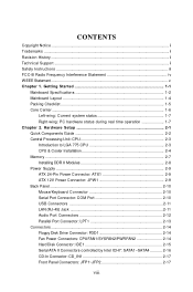
... Setup 2-1 Quick Components Guide 2-2 Central Processing Unit: CPU 2-3 Introduction to LGA 775 CPU 2-3 CPU & Cooler Installation 2-4 Memory ...2-7 Installing DDR II Modules 2-8 Power Supply ...2-9 ATX 24-Pin Power Connector: ATX1 2-9 ATX 12V Power Connector: JPW 1 2-9 Back Panel ...2-10 Mouse/Keyboard Connector 2-10 Serial Port Connector: COM Port 2-10 USB Connectors 2-11 LAN (RJ-45) Jack 2-11 Audio Port Connectors 2-12 Parallel Port Connector: LPT1 2-13 Connectors ...2-14 Floppy Disk Drive Connector: FDD1 2-14 Fan Power Connectors: CPUFAN1/SYSFAN2/PWRFAN2 2-14 Hard Disk...
... Setup 2-1 Quick Components Guide 2-2 Central Processing Unit: CPU 2-3 Introduction to LGA 775 CPU 2-3 CPU & Cooler Installation 2-4 Memory ...2-7 Installing DDR II Modules 2-8 Power Supply ...2-9 ATX 24-Pin Power Connector: ATX1 2-9 ATX 12V Power Connector: JPW 1 2-9 Back Panel ...2-10 Mouse/Keyboard Connector 2-10 Serial Port Connector: COM Port 2-10 USB Connectors 2-11 LAN (RJ-45) Jack 2-11 Audio Port Connectors 2-12 Parallel Port Connector: LPT1 2-13 Connectors ...2-14 Floppy Disk Drive Connector: FDD1 2-14 Fan Power Connectors: CPUFAN1/SYSFAN2/PWRFAN2 2-14 Hard Disk...

User Guide
Page 9
Front USB Connectors: JUSB1~JUSB2 2-18 Front Panel Audio Connector: JAUD1 2-18 Chassis Intrusion Switch Connector: JCI1 2-19 SPDIF-Out Connector: JSPD1 2-19 Jumpers ...2-20 Clear CMOS Jumper: JBAT1 2-20 Slots ...2-21 PCI Express Slots 2-21 PCI (Peripheral Component Interconnect) Slots 2-21 PCI Interrupt Request Routing 2-21 Chapter 3. BIOS Setup 3-1 Entering Setup ...3-2 Control Keys 3-3 Getting Help 3-3 General Help
Front USB Connectors: JUSB1~JUSB2 2-18 Front Panel Audio Connector: JAUD1 2-18 Chassis Intrusion Switch Connector: JCI1 2-19 SPDIF-Out Connector: JSPD1 2-19 Jumpers ...2-20 Clear CMOS Jumper: JBAT1 2-20 Slots ...2-21 PCI Express Slots 2-21 PCI (Peripheral Component Interconnect) Slots 2-21 PCI Interrupt Request Routing 2-21 Chapter 3. BIOS Setup 3-1 Entering Setup ...3-2 Control Keys 3-3 Getting Help 3-3 General Help
User Guide
Page 11
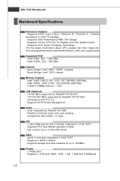
... - Flexible 8-channel audio with Fan Speed Control - Supports 1 FDD with PCI 2.2 - Supports Intel® Core 2 Duo / Pentium D / Pentium 4 / Celeron processors in Intel® ICH7 - Supports Intel Hyper-Threading Technology (For the latest information about CPU, please visit http://www.msi. php) Supported FSB - Supports ACPI Power Managem ent Audio - Supports storage and data transfers at up to 300MB/s Floppy - 1 floppy port - Supports 4 SATA II Device - Intel® 945P: 800 / 1066 MHz - Chip integrated by Realtek® RTL8110SC - Supports PIO, Bus Master...
... - Flexible 8-channel audio with Fan Speed Control - Supports 1 FDD with PCI 2.2 - Supports Intel® Core 2 Duo / Pentium D / Pentium 4 / Celeron processors in Intel® ICH7 - Supports Intel Hyper-Threading Technology (For the latest information about CPU, please visit http://www.msi. php) Supported FSB - Supports ACPI Power Managem ent Audio - Supports storage and data transfers at up to 300MB/s Floppy - 1 floppy port - Supports 4 SATA II Device - Intel® 945P: 800 / 1066 MHz - Chip integrated by Realtek® RTL8110SC - Supports PIO, Bus Master...
User Guide
Page 19
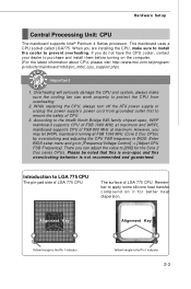
... computer. (For the latest information about CPU, please visit http://www.msi.com.tw/program/ p ro du c t s / ma in BIOS: Enter BIOS setup menu and go to [Frequency/Voltage Control] -> [Adjust CPU FSB Frequency]. Please be noted that this is over-spec and this overclocking behavior is the Pin 1 indicator 2-3 The mainboard uses a CPU socket called LGA775. When you may let 945PL mainboard running at maximum. Introduction to prevent overheating...
... computer. (For the latest information about CPU, please visit http://www.msi.com.tw/program/ p ro du c t s / ma in BIOS: Enter BIOS setup menu and go to [Frequency/Voltage Control] -> [Adjust CPU FSB Frequency]. Please be noted that this is over-spec and this overclocking behavior is the Pin 1 indicator 2-3 The mainboard uses a CPU socket called LGA775. When you may let 945PL mainboard running at maximum. Introduction to prevent overheating...

User Guide
Page 23
... is not backward compatible, you install memory modules of the same type and density in boa rd /m bd /pr o_ mb d_ tr p_lis t. ph p) From left to boot up , always insert the memory mod- To enable successful system boot-up your system and your mainboard might be damaged. (For the updated supporting memory modules, please visit http://www.msi. tw /p rog ra...
... is not backward compatible, you install memory modules of the same type and density in boa rd /m bd /pr o_ mb d_ tr p_lis t. ph p) From left to boot up , always insert the memory mod- To enable successful system boot-up your system and your mainboard might be damaged. (For the updated supporting memory modules, please visit http://www.msi. tw /p rog ra...

User Guide
Page 25
... ATX 12V Power Connector: JPW1 This 12V power connector is highly recommended for the power system. Power supply of the mainboard. 2. ATX 24-Pin Power Connector: ATX1 This connector allows you to the CPU. 3 4 1 2 JPW1 Pin Definition PIN SIGNAL 1 GND 2 GND 3 12V 4 12V Important 1. ATX 12V power connection should be caused. These two connectors connect to the ATX power supply and have to work together to ensure that no damage will be greater than 18A. 2-9 Hardware Setup Power Supply The mainboard supports ATX power supply...
... ATX 12V Power Connector: JPW1 This 12V power connector is highly recommended for the power system. Power supply of the mainboard. 2. ATX 24-Pin Power Connector: ATX1 This connector allows you to the CPU. 3 4 1 2 JPW1 Pin Definition PIN SIGNAL 1 GND 2 GND 3 12V 4 12V Important 1. ATX 12V power connection should be caused. These two connectors connect to the ATX power supply and have to work together to ensure that no damage will be greater than 18A. 2-9 Hardware Setup Power Supply The mainboard supports ATX power supply...

User Guide
Page 31
... connect up to Slave mode by setting the jumper accordingly. Important If you install two hard disks on cable, you must configure second hard drive to the hard disk documentation supplied by hard disk vendors for jumper setting instructions. 2-15 You must configure the second drive to two Ultra ATA drives. Refer to Slave mode by setting its jumper. Hardware Setup Hard Disk Connector: IDE1 The mainboard has 32-bit Ultra DMA 66/100 IDE controllers integrated in the chips Intel ICH7, which supports PIO & Bus...
... connect up to Slave mode by setting the jumper accordingly. Important If you install two hard disks on cable, you must configure second hard drive to the hard disk documentation supplied by hard disk vendors for jumper setting instructions. 2-15 You must configure the second drive to two Ultra ATA drives. Refer to Slave mode by setting its jumper. Hardware Setup Hard Disk Connector: IDE1 The mainboard has 32-bit Ultra DMA 66/100 IDE controllers integrated in the chips Intel ICH7, which supports PIO & Bus...
User Guide
Page 34
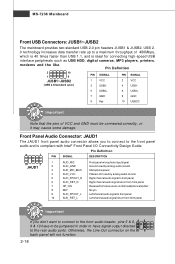
... Reserved for connecting high-speed USB interface peripherals such as USB HDD, digital cameras, MP3 players, printers, modems and the like. MS-7236 Mainboard Front USB Connectors: JUSB1~JUSB2 The mainboard provides two standard USB 2.0 pin headers JUSB1 & JUSB2. Front Panel Audio Connector: JAUD1 The JAUD1 front panel audio connector allows you to connect to the front panel audio and is ideal for future use to control headphone amplifier 8 KEY No pin 9 AUD_FPOUT_L Left channel audio signal to...
... Reserved for connecting high-speed USB interface peripherals such as USB HDD, digital cameras, MP3 players, printers, modems and the like. MS-7236 Mainboard Front USB Connectors: JUSB1~JUSB2 The mainboard provides two standard USB 2.0 pin headers JUSB1 & JUSB2. Front Panel Audio Connector: JAUD1 The JAUD1 front panel audio connector allows you to connect to the front panel audio and is ideal for future use to control headphone amplifier 8 KEY No pin 9 AUD_FPOUT_L Left channel audio signal to...

User Guide
Page 36
... change your motherboard's function through the use the JBAT1 (Clear CMOS) Jumper to set the computer's function. Then return to keep the system configuration data. W ith the CMOS RAM, the system can clear CMOS by shorting 2-3 pin while the system is turned on. it is off. This section will damage the mainboard. 2-20 Avoid clearing the CMOS while the system is a CMOS RAM on ; Clear CMOS Jumper: JBAT1 There is on board that has a power supply...
... change your motherboard's function through the use the JBAT1 (Clear CMOS) Jumper to set the computer's function. Then return to keep the system configuration data. W ith the CMOS RAM, the system can clear CMOS by shorting 2-3 pin while the system is turned on. it is off. This section will damage the mainboard. 2-20 Avoid clearing the CMOS while the system is a CMOS RAM on ; Clear CMOS Jumper: JBAT1 There is on board that has a power supply...

User Guide
Page 37
..., 1394 controllers, and general purpose I -R-Q, are typically connected to the microprocessor. Hardware Setup Slots The mainboard provides one PCI Express x16 slot, two PCI Express x1 slots and three 32-bit PCI bus slots. PCI Express Slots The PCI Express slots, as jumpers, switches or BIOS configuration. PCI Express architecture provides a high performance I/O infrastructure for the expansion card, such as a high-bandwidth, low pin count, serial, interconnect technology, support Intel highest performance desktop platforms utilizing the Intel Pentium 4 processor with PCI Express...
..., 1394 controllers, and general purpose I -R-Q, are typically connected to the microprocessor. Hardware Setup Slots The mainboard provides one PCI Express x16 slot, two PCI Express x1 slots and three 32-bit PCI bus slots. PCI Express Slots The PCI Express slots, as jumpers, switches or BIOS configuration. PCI Express architecture provides a high performance I/O infrastructure for the expansion card, such as a high-bandwidth, low pin count, serial, interconnect technology, support Intel highest performance desktop platforms utilizing the Intel Pentium 4 processor with PCI Express...
User Guide
Page 45
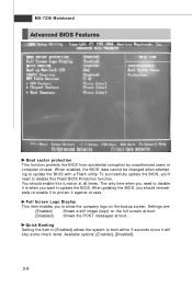
... to disable it is when you should enable this Flash BIOS Protection function. MS-7236 Mainboard Advanced BIOS Features Boot sector protection This function protects the BIOS from accidental corruption by unauthorized users or computer viruses. Full Screen Logo Display This item enables you 'll need to protect it will skip some check items. Available options: [Enabled], [Disabled]. 3-8 To successfully update the BIOS, you to update the BIOS with a Flash utility.
... to disable it is when you should enable this Flash BIOS Protection function. MS-7236 Mainboard Advanced BIOS Features Boot sector protection This function protects the BIOS from accidental corruption by unauthorized users or computer viruses. Full Screen Logo Display This item enables you 'll need to protect it will skip some check items. Available options: [Enabled], [Disabled]. 3-8 To successfully update the BIOS, you to update the BIOS with a Flash utility.

User Guide
Page 46
....0 operating system. [Disabled] Set to [Disabled] if you to select which version to use the arrow keys on . To find out which MPS (Multi-Processor Specification) version to be used to run in APIC mode. CPU Feature Press to enter the sub-menu and the following screen appears: Execute Bit Support Execute Bit Support is a robust hardware feature, detectable using the CPUIDinstruction, that protects against malicious software executing code on . IOAPIC Function...
....0 operating system. [Disabled] Set to [Disabled] if you to select which version to use the arrow keys on . To find out which MPS (Multi-Processor Specification) version to be used to run in APIC mode. CPU Feature Press to enter the sub-menu and the following screen appears: Execute Bit Support Execute Bit Support is a robust hardware feature, detectable using the CPUIDinstruction, that protects against malicious software executing code on . IOAPIC Function...
User Guide
Page 47
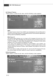
... the graphics card and the motherboard. When [Enabled], the PCI Express X16 slot will be forced to run in the PCI Express X1 mode. But if you should disable this BIOS feature to ensure maximum compatibility. PEG Force X1 This BIOS feature allows you to convert a PCI Express X16 slot into the PCI Express X16 slot, you need to install a PCI Express X1 card into a PCI Express X1 slot. Setting options: [Enabled], [Disabled]. MS-7236 Mainboard Chipset Feature Press to enter the sub-menu and...
... the graphics card and the motherboard. When [Enabled], the PCI Express X16 slot will be forced to run in the PCI Express X1 mode. But if you should disable this BIOS feature to ensure maximum compatibility. PEG Force X1 This BIOS feature allows you to convert a PCI Express X16 slot into the PCI Express X16 slot, you need to install a PCI Express X1 card into a PCI Express X1 slot. Setting options: [Enabled], [Disabled]. MS-7236 Mainboard Chipset Feature Press to enter the sub-menu and...

User Guide
Page 49
...LAN Option ROM The item enables or disables the initialization of the onboard LAN Boot ROMs during bootup. HD Audio Controller The field enables or disables the HD Audio controller. Setting options:[Enabled], [Disabled]. 3-12 USB Device Legacy Support Set to [Enabled] if you need to use any USB 1.1/2.0 device in the operating system that does not support or have USB peripherals. Setting options: [Enabled], [Disabled]. Setting options: [Enabled], [Disabled]. MS-7236 Mainboard Integrated Peripherals USB Controller Select [Enabled] if your system contains a Universal Serial Bus...
...LAN Option ROM The item enables or disables the initialization of the onboard LAN Boot ROMs during bootup. HD Audio Controller The field enables or disables the HD Audio controller. Setting options:[Enabled], [Disabled]. 3-12 USB Device Legacy Support Set to [Enabled] if you need to use any USB 1.1/2.0 device in the operating system that does not support or have USB peripherals. Setting options: [Enabled], [Disabled]. Setting options: [Enabled], [Disabled]. MS-7236 Mainboard Integrated Peripherals USB Controller Select [Enabled] if your system contains a Universal Serial Bus...

User Guide
Page 50
... the following screen appears: On-Chip IDE Controller The integrated peripheral controller contains a IDE interface with support for two IDE channels. BIOS Setup On-Chip ATA Device Press to enter the sub-menu and the following options: [Disabled] [3BC/IRQ7] Line Printer port 0 [278/IRQ5] Line Printer port 2 [378/IRQ7] Line Printer port 1 3-13 On-Chip ATA Device Press to automatically determine the correct base I /O port addresses of the onboard Serial Port 1 (COM 1). Selecting [Auto] allows AMIBIOS...
... the following screen appears: On-Chip IDE Controller The integrated peripheral controller contains a IDE interface with support for two IDE channels. BIOS Setup On-Chip ATA Device Press to enter the sub-menu and the following options: [Disabled] [3BC/IRQ7] Line Printer port 0 [278/IRQ5] Line Printer port 2 [378/IRQ7] Line Printer port 1 3-13 On-Chip ATA Device Press to automatically determine the correct base I /O port addresses of the onboard Serial Port 1 (COM 1). Selecting [Auto] allows AMIBIOS...

User Guide
Page 52
... to main memory that remains powered while most other hardware components turn off to activate the ACPI (Advanced Configuration and Power Management Interface) Function. Options are: [S1] The S1 sleep mode is a low power state. ACPI Standby State This item specifies the power saving modes for ACPI function. In this field. Power Management Setup BIOS Setup ACPI Function This item is to save energy. If your operating system supports ACPI, such as Windows...
... to main memory that remains powered while most other hardware components turn off to activate the ACPI (Advanced Configuration and Power Management Interface) Function. Options are: [S1] The S1 sleep mode is a low power state. ACPI Standby State This item specifies the power saving modes for ACPI function. In this field. Power Management Setup BIOS Setup ACPI Function This item is to save energy. If your operating system supports ACPI, such as Windows...

User Guide
Page 55
... Mainboard PnP/PCI Configurations This section describes configuring the PCI bus system and PnP (Plug & Play) feature. If a PCI VGA card is strongly recommended that only experienced users should set to operate at speeds nearing the speed the CPU itself uses when communicating with its special components. PCI Latency Timer This item controls how long each PCI device can conduct transactions for a longer time and thus improve the effective PCI bandwidth. Primary Graphic...
... Mainboard PnP/PCI Configurations This section describes configuring the PCI bus system and PnP (Plug & Play) feature. If a PCI VGA card is strongly recommended that only experienced users should set to operate at speeds nearing the speed the CPU itself uses when communicating with its special components. PCI Latency Timer This item controls how long each PCI device can conduct transactions for a longer time and thus improve the effective PCI bandwidth. Primary Graphic...

User Guide
Page 57
... is once opened. Chassis Intrusion The field enables or disables the feature of your CPU, fan, overall system status, etc. Setting options: [Disabled], [Enabled], [Reset]. CPU Smart Fan Target The mainboard provides the CPU Smart Fan system which can control the fan speed automatically depending on the current temperature to [Reset]. The setting of the monitored hardware devices/ components such as CPU voltages, temperatures and all of the field will automatically return to [Enabled] later. To clear the warning message...
... is once opened. Chassis Intrusion The field enables or disables the feature of your CPU, fan, overall system status, etc. Setting options: [Disabled], [Enabled], [Reset]. CPU Smart Fan Target The mainboard provides the CPU Smart Fan system which can control the fan speed automatically depending on the current temperature to [Reset]. The setting of the monitored hardware devices/ components such as CPU voltages, temperatures and all of the field will automatically return to [Enabled] later. To clear the warning message...

User Guide
Page 59
... Bus clock frequency (in MHz). You need to restart the system to load the new memory frequency you choose. (read only) Adjust DRAM Frequency Adjusting the DRAM voltage can increase the DDR speed. You need to restart the system to select the AGP/PCI frequency (in MHz) and overclock the processor by using the & key. Intel EIST The Enhanced Intel SpeedStep technology allows you installed the CPU which support speedstep technology. Setting options: For CPU...
... Bus clock frequency (in MHz). You need to restart the system to load the new memory frequency you choose. (read only) Adjust DRAM Frequency Adjusting the DRAM voltage can increase the DDR speed. You need to restart the system to select the AGP/PCI frequency (in MHz) and overclock the processor by using the & key. Intel EIST The Enhanced Intel SpeedStep technology allows you installed the CPU which support speedstep technology. Setting options: For CPU...


