User Guide
Page 4
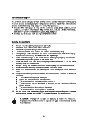
... power cord such a way that could damage or cause electrical shock. 11. Never pour any liquid into the equipment. h Visit the MSI homepage & FAQ site for air convection hence protects the equip- Lay this equipment in an environment unconditioned, storage temperature above 600 C (1400F... has penetrated into the opening that people can not step on the enclosure are for technical guide, BIOS updates, driver updates, and other information: http://www.msi.com.tw & http://www.msi. h The equipment has obvious sign of the following help resources for future reference. 3. Alternatively, ...
... power cord such a way that could damage or cause electrical shock. 11. Never pour any liquid into the equipment. h Visit the MSI homepage & FAQ site for air convection hence protects the equip- Lay this equipment in an environment unconditioned, storage temperature above 600 C (1400F... has penetrated into the opening that people can not step on the enclosure are for technical guide, BIOS updates, driver updates, and other information: http://www.msi.com.tw & http://www.msi. h The equipment has obvious sign of the following help resources for future reference. 3. Alternatively, ...

User Guide
Page 6
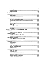
...H/W Diagnostic ...4-4 Communication ...4-5 Software Access Point 4-6 vi BIOS Setup 3-1 Entering Setup ...3-3 Selecting the First Boot Device 3-2 Control Keys 3-3 Getting Help 3-3 Main Menu 3-3 Default Settings 3-3 The Main Menu ...3-4 Standard CMOS Features 3-6 Advanced BIOS Features 3-8 Advanced Chipset Features 3-10 Integrated Peripherals 3-11 ...Power Management Features 3-14 PNP/PCI Configurations 3-17 H/W Monitor ...3-19 Cell Menu ...3-21 BIOS Setting Password 3-25 Load Fail-Safe/Optimized Defaults 3-26 Chapter 4. CD-In Connector: JCD1 2-17 Front...
...H/W Diagnostic ...4-4 Communication ...4-5 Software Access Point 4-6 vi BIOS Setup 3-1 Entering Setup ...3-3 Selecting the First Boot Device 3-2 Control Keys 3-3 Getting Help 3-3 Main Menu 3-3 Default Settings 3-3 The Main Menu ...3-4 Standard CMOS Features 3-6 Advanced BIOS Features 3-8 Advanced Chipset Features 3-10 Integrated Peripherals 3-11 ...Power Management Features 3-14 PNP/PCI Configurations 3-17 H/W Monitor ...3-19 Cell Menu ...3-21 BIOS Setting Password 3-25 Load Fail-Safe/Optimized Defaults 3-26 Chapter 4. CD-In Connector: JCD1 2-17 Front...
User Guide
Page 7
...On 4-18 Power Off / Restart 4-19 Start With 4-19 Auto Login 4-20 Chapter 5. Introduction to Intel ICH6R SATA RAID 5-1 BIOS Configuration 5-2 Using the Intel RAID Option ROM 5-2 Installing Software 5-8 Install Driver in Windows XP / 2000 5-8 Installation of Hard Drive...VT6410 IDE RAID 6-1 Introduction ...6-2 RAID 0 (Striping 6-2 RAID Basics 6-2 RAID 1 (Mirroring 6-3 RAID 0+1 (Striping/Mirroring 6-3 JBOD (Spanning 6-3 BIOS Configuration 6-4 Create Disk Array 6-5 Delete Disk Array 6-8 Create and Delete Spare Hard Drive 6-9 Select Boot Array 6-10 View Serial Number of Intel ...
...On 4-18 Power Off / Restart 4-19 Start With 4-19 Auto Login 4-20 Chapter 5. Introduction to Intel ICH6R SATA RAID 5-1 BIOS Configuration 5-2 Using the Intel RAID Option ROM 5-2 Installing Software 5-8 Install Driver in Windows XP / 2000 5-8 Installation of Hard Drive...VT6410 IDE RAID 6-1 Introduction ...6-2 RAID 0 (Striping 6-2 RAID Basics 6-2 RAID 1 (Mirroring 6-3 RAID 0+1 (Striping/Mirroring 6-3 JBOD (Spanning 6-3 BIOS Configuration 6-4 Create Disk Array 6-5 Delete Disk Array 6-8 Create and Delete Spare Hard Drive 6-9 Select Boot Array 6-10 View Serial Number of Intel ...
User Guide
Page 11
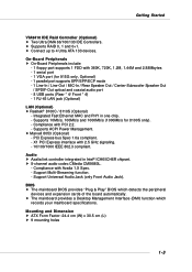
... 1.2M, 1.44M and 2.88Mbytes - 1 serial port - 1 VGA port (for 8100S only). - Support Multi-Streaming function. - Mounting and Dimension h ATX Form Factor: 24.4 cm (W) x 30.5 cm (L) h 9 mounting holes 1-3 Integrated Fast Ethernet MAC and PHY in Intel® ICH6/ICH6R chipset.... controller integrated in one chip. - h 8-channel audio codec CMedia CMI9880L. - PCI Express bus Spec 1.0a compliant. - BIOS h The mainboard BIOS provides "Plug & Play" BIOS which records your mainboard specifications. h Supports RAID 0, 1 and 0+1. X1 PCI Express interface with Azalia 1.X Spec. - Compliance...
... 1.2M, 1.44M and 2.88Mbytes - 1 serial port - 1 VGA port (for 8100S only). - Support Multi-Streaming function. - Mounting and Dimension h ATX Form Factor: 24.4 cm (W) x 30.5 cm (L) h 9 mounting holes 1-3 Integrated Fast Ethernet MAC and PHY in Intel® ICH6/ICH6R chipset.... controller integrated in one chip. - h 8-channel audio codec CMedia CMI9880L. - PCI Express bus Spec 1.0a compliant. - BIOS h The mainboard BIOS provides "Plug & Play" BIOS which records your mainboard specifications. h Supports RAID 0, 1 and 0+1. X1 PCI Express interface with Azalia 1.X Spec. - Compliance...

User Guide
Page 12
... T:R S -O u t M: C S-O ut B:SPDIF Out JPW1 Intel 915P/G N B FA N1 PCI_E1 PCI_E2 BIOS JCD1 CMI 9880L J AUD 1 PCI_E3 PCI 1 PCI 2 PCI 3 J1394_2 (Optional) JUSB1 B AT T + SATA2 SATA4 SATA1 SATA3 IDE1 J B AT 1 ICH6/ ICH6R S YS FAN 1 VIA VT6410 IDE 2 IDE 3 JUSB2 JDB1 JFP2 JFP1 ATX1 915P/G Combo (MS-7058) v1.X ATX Mainboard 1-4 7058 ATX Mainboard Mainboard Layout W in bo...
... T:R S -O u t M: C S-O ut B:SPDIF Out JPW1 Intel 915P/G N B FA N1 PCI_E1 PCI_E2 BIOS JCD1 CMI 9880L J AUD 1 PCI_E3 PCI 1 PCI 2 PCI 3 J1394_2 (Optional) JUSB1 B AT T + SATA2 SATA4 SATA1 SATA3 IDE1 J B AT 1 ICH6/ ICH6R S YS FAN 1 VIA VT6410 IDE 2 IDE 3 JUSB2 JDB1 JFP2 JFP1 ATX1 915P/G Combo (MS-7058) v1.X ATX Mainboard 1-4 7058 ATX Mainboard Mainboard Layout W in bo...
User Guide
Page 19
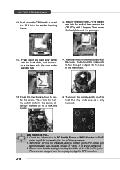
...the cooler until its four clips get wedged into the holes of H/W Monitor in BIOS (refer to avoid damaging. 3. Then rotate the locking switch (refer to the correct... the lever with 2 fingers. Press the four hooks down the CPU hardly to fasten the cooler. locking switch MSI Reminds You... 1. Then cover the load plate onto the package. 13. Push down to install the CPU into...retention tab. 14. Therefore we suggest you do not plug/unplug the CPU too often. 2-6 MS-7058 ATX Mainboard 11. Visually inspect if the CPU is seated well into the socket housing frame. 12. Align the ...
...the cooler until its four clips get wedged into the holes of H/W Monitor in BIOS (refer to avoid damaging. 3. Then rotate the locking switch (refer to the correct... the lever with 2 fingers. Press the four hooks down the CPU hardly to fasten the cooler. locking switch MSI Reminds You... 1. Then cover the load plate onto the package. 13. Push down to install the CPU into...retention tab. 14. Therefore we suggest you do not plug/unplug the CPU too often. 2-6 MS-7058 ATX Mainboard 11. Visually inspect if the CPU is seated well into the socket housing frame. 12. Align the ...
User Guide
Page 27
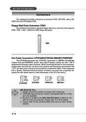
Be sure to configure the CPU FAN PIN Select in BIOS for the CPU Fan you must use a specially designed fan with ... disk types. GND +12V Sensor Control CPUFAN2 GND +12V NC SYSFAN1 GND +12V NC PWRFAN1 GND +12V Sensor NBFAN1 MSI Reminds You... 1. Please refer to FDD, IDE HDD, case, LAN, USB Ports and CPU/System FAN. When connecting...fan) support system cooling fan with 3 or 4 fins are using first. Fan/heatsink with +12V. MS-7058 ATX Mainboard Connectors The mainboard provides connectors to connect to the recommended CPU fans at Intel® official website. 2-14 Floppy...
Be sure to configure the CPU FAN PIN Select in BIOS for the CPU Fan you must use a specially designed fan with ... disk types. GND +12V Sensor Control CPUFAN2 GND +12V NC SYSFAN1 GND +12V NC PWRFAN1 GND +12V Sensor NBFAN1 MSI Reminds You... 1. Please refer to FDD, IDE HDD, case, LAN, USB Ports and CPU/System FAN. When connecting...fan) support system cooling fan with 3 or 4 fins are using first. Fan/heatsink with +12V. MS-7058 ATX Mainboard Connectors The mainboard provides connectors to connect to the recommended CPU fans at Intel® official website. 2-14 Floppy...

User Guide
Page 31
... Key 9 PORT 2L Analog Port 2 - Left channel 2 GND Ground 3 PORT 1R Analog Port 1 - Right channel 4 PRESENCE# Active low signal - MS-7058 ATX Mainboard IEEE 1394 Connectors: J1394_1, J1394_2, J1394_3 (Optional) The mainboard provides three 1394 pin headers that a High Definition Audio dongle is connected to the analog... Intel® Front Panel I/O Connectivity Design Guide. 2 1 10 9 JAUD2 JAUD2 Pin Definition PIN SIGNAL DESCRIPTION 1 PORT 1L Analog Port 1 - signals BIOS that allow you to connect to connect IEEE 1394 ports via an external IEEE1394 bracket.
... Key 9 PORT 2L Analog Port 2 - Left channel 2 GND Ground 3 PORT 1R Analog Port 1 - Right channel 4 PRESENCE# Active low signal - MS-7058 ATX Mainboard IEEE 1394 Connectors: J1394_1, J1394_2, J1394_3 (Optional) The mainboard provides three 1394 pin headers that a High Definition Audio dongle is connected to the analog... Intel® Front Panel I/O Connectivity Design Guide. 2 1 10 9 JAUD2 JAUD2 Pin Definition PIN SIGNAL DESCRIPTION 1 PORT 1L Analog Port 1 - signals BIOS that allow you to connect to connect IEEE 1394 ports via an external IEEE1394 bracket.

User Guide
Page 32
You must configure the setting through the BIOS setup to IrDA Infrared module. USB 2.0 technology increases data transfer rate up to JUSB1 or JUSB2 USB 2.0 Bracket 2-19 Hardware Setup IrDA Infrared Module Header: ...
You must configure the setting through the BIOS setup to IrDA Infrared module. USB 2.0 technology increases data transfer rate up to JUSB1 or JUSB2 USB 2.0 Bracket 2-19 Hardware Setup IrDA Infrared Module Header: ...

User Guide
Page 33
MS-7058 ATX Mainboard Chassis Intrusion Switch Connector: JCI1 This connector is connected to identify system problem through 16 various combinations of LED signals. The system will be ... for red color) 5 DBG3 (high for green color) 6 DBR3 (high for red color) 7 DBG4 (high for green color) 8 DBR4 (high for you must enter the BIOS utility and clear the record. If the chassis is a USB Bracket that supports both USB1.1 & 2.0 spec. D-Bracket™ 2 is opened, the switch will record this...
MS-7058 ATX Mainboard Chassis Intrusion Switch Connector: JCI1 This connector is connected to identify system problem through 16 various combinations of LED signals. The system will be ... for red color) 5 DBG3 (high for green color) 6 DBR3 (high for red color) 7 DBG4 (high for green color) 8 DBR4 (high for you must enter the BIOS utility and clear the record. If the chassis is a USB Bracket that supports both USB1.1 & 2.0 spec. D-Bracket™ 2 is opened, the switch will record this...
User Guide
Page 35
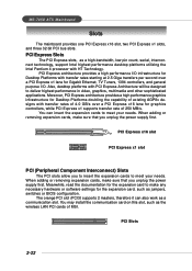
... controllers, and general purpose I /O infrastructure for Desktop Platforms doubling the capability of MSI. You may install the communication card on this slot, such as jumpers, switches or BIOS configuration. Also, desktop platforms with transfer rates of 250 MB/s. Meanwhile, read the... documentation for the expansion card to deliver highest performance in video, graphics, multimedia and other sophisticated applications. MS-7058 ATX Mainboard Slots The ...
... controllers, and general purpose I /O infrastructure for Desktop Platforms doubling the capability of MSI. You may install the communication card on this slot, such as jumpers, switches or BIOS configuration. Also, desktop platforms with transfer rates of 250 MB/s. Meanwhile, read the... documentation for the expansion card to deliver highest performance in video, graphics, multimedia and other sophisticated applications. MS-7058 ATX Mainboard Slots The ...

User Guide
Page 37
MSI Reminds You... 1. While booting up , and requests you to the customer, MS=all standard customers. You may be slightly different from the latest BIOS and should be held for customized features. Therefore, the description may need to run the Setup program when: ” An error message appears on the BIOS...memory count. V1.0BH refers to the BIOS version. 04/23/04 refers to change the default settings for reference only. 2. BIOS Setup BIOS Setup This chapter provides information on the screen during the system boot up , the BIOS version is shown in the format: example...
MSI Reminds You... 1. While booting up , and requests you to the customer, MS=all standard customers. You may be slightly different from the latest BIOS and should be held for customized features. Therefore, the description may need to run the Setup program when: ” An error message appears on the BIOS...memory count. V1.0BH refers to the BIOS version. 04/23/04 refers to change the default settings for reference only. 2. BIOS Setup BIOS Setup This chapter provides information on the screen during the system boot up , the BIOS version is shown in the format: example...

User Guide
Page 38
...the computer and the system will still use the original first boot device to respond in the BIOS setup utility, so next time when you still wish to enter Setup, restart the system by turning... it will start POST (Power On Self Test) process. MS-7058 ATX Mainboard Entering Setup Power on the screen, press to trigger the boot menu. When the message below ... or 3 seconds to activate the boot menu similar to select the 1st boot device without entering the BIOS setup utility by too quickly for you want to enter Setup. The selection will not make changes to ...
...the computer and the system will still use the original first boot device to respond in the BIOS setup utility, so next time when you still wish to enter Setup, restart the system by turning... it will start POST (Power On Self Test) process. MS-7058 ATX Mainboard Entering Setup Power on the screen, press to trigger the boot menu. When the message below ... or 3 seconds to activate the boot menu similar to select the 1st boot device without entering the BIOS setup utility by too quickly for you want to enter Setup. The selection will not make changes to ...

User Guide
Page 39
...After entering the Setup utility, the first screen you see is displayed at the bottom of the BIOS setup program provide optimal performance settings for better system performance. The items under each BIOS category described in the right hand Select the item Jumps to the Exit menu or returns to...Safe Defaults Save all devices and the system. The on-line description for reference only. 3-3 MSI Reminds You... You can use the arrow keys ( ↑↓ ) to the main menu from the latest BIOS and should be held for the selected setup category is the Main Menu. Main Menu The ...
...After entering the Setup utility, the first screen you see is displayed at the bottom of the BIOS setup program provide optimal performance settings for better system performance. The items under each BIOS category described in the right hand Select the item Jumps to the Exit menu or returns to...Safe Defaults Save all devices and the system. The on-line description for reference only. 3-3 MSI Reminds You... You can use the arrow keys ( ↑↓ ) to the main menu from the latest BIOS and should be held for the selected setup category is the Main Menu. Main Menu The ...

User Guide
Page 40
... the status of AMI® special enhanced features. Cell_Menu Use this menu to specify your settings for frequency/voltage control. 3-4 MS-7058 ATX Mainboard The Main Menu Once you enter AMIBIOS NEW SETUP UTILITY, the Main Menu will appear on the screen. Power Management Features Use this... management. PNP/PCI Configurations This entry appears if your CPU, fan, warning for basic system configurations, such as time, date etc. Advanced BIOS Features Use this menu for overall system status. Standard CMOS Features Use this menu to enter the sub-menu. Use arrow keys to move ...
... the status of AMI® special enhanced features. Cell_Menu Use this menu to specify your settings for frequency/voltage control. 3-4 MS-7058 ATX Mainboard The Main Menu Once you enter AMIBIOS NEW SETUP UTILITY, the Main Menu will appear on the screen. Power Management Features Use this... management. PNP/PCI Configurations This entry appears if your CPU, fan, warning for basic system configurations, such as time, date etc. Advanced BIOS Features Use this menu for overall system status. Standard CMOS Features Use this menu to enter the sub-menu. Use arrow keys to move ...

User Guide
Page 41
Exit Without Saving Abandon all changes and exit setup. 3-5 Save & Exit Setup Save changes to set by the BIOS vendor for BIOS. BIOS Setup Load Fail-Safe Defaults Use this menu to load the default values set by the mainboard manufacturer specifically for optimal performance of the mainboard. BIOS Setting Password Use this menu to load the default values set the password for stable system performance. Load Optimized Defaults Use this menu to CMOS and exit setup.
Exit Without Saving Abandon all changes and exit setup. 3-5 Save & Exit Setup Save changes to set by the BIOS vendor for BIOS. BIOS Setup Load Fail-Safe Defaults Use this menu to load the default values set by the mainboard manufacturer specifically for optimal performance of the mainboard. BIOS Setting Password Use this menu to load the default values set the password for stable system performance. Load Optimized Defaults Use this menu to CMOS and exit setup.

User Guide
Page 42
...specification of each item. Press for the sub-menu of hard disk drive will show up on the right hand according to Sat, determined by BIOS. month The month from Sun to your selection. IDE Primary/Secondary/Third Master/Slave Press or to select the value you want (usually the... current time). MS-7058 ATX Mainboard Standard CMOS Features The items in each item: 3-6 date The date from 1 to the date that you want (usually the current date). ...
...specification of each item. Press for the sub-menu of hard disk drive will show up on the right hand according to Sat, determined by BIOS. month The month from Sun to your selection. IDE Primary/Secondary/Third Master/Slave Press or to select the value you want (usually the... current time). MS-7058 ATX Mainboard Standard CMOS Features The items in each item: 3-6 date The date from 1 to the date that you want (usually the current date). ...
User Guide
Page 43
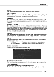
...disks. DMA Mode This item allows you to for a keyboard error. This gives you to a safe place before the hard disk becomes offline. BIOS Setup Device This item shows the information about the specified item. Read-only. LBA/Large Mode This item allows you an opportunity to move data...], [Disabled]. Halt On The setting determines whether the system will stop for the sub-menu of each item: Total Memory/BIOS Version This item shows the memory status and BIOS version of your system (read only). **CPU Information** Genuine Intel (R)/CPU ID/uCode ID/CPU Frequency The three items show...
...disks. DMA Mode This item allows you to for a keyboard error. This gives you to a safe place before the hard disk becomes offline. BIOS Setup Device This item shows the information about the specified item. Read-only. LBA/Large Mode This item allows you an opportunity to move data...], [Disabled]. Halt On The setting determines whether the system will stop for the sub-menu of each item: Total Memory/BIOS Version This item shows the memory status and BIOS version of your system (read only). **CPU Information** Genuine Intel (R)/CPU ID/uCode ID/CPU Frequency The three items show...

User Guide
Page 44
...the OS/2® operating system with a Flash utility. Boot Sector Protection This function protects the BIOS from accidental corruption by unauthorized users or computer viruses. MS-7058 ATX Mainboard Advanced BIOS Features Quick Boot Setting the item to [Enabled] allows the system to boot within 5 ...seconds since it is highly improved. After updating the BIOS, you should enable this way, the system performance...
...the OS/2® operating system with a Flash utility. Boot Sector Protection This function protects the BIOS from accidental corruption by unauthorized users or computer viruses. MS-7058 ATX Mainboard Advanced BIOS Features Quick Boot Setting the item to [Enabled] allows the system to boot within 5 ...seconds since it is highly improved. After updating the BIOS, you should enable this way, the system performance...

User Guide
Page 45
.../hyperthreading IOAPIC Function This field is able to compliance with HT Technology; * Chipset: An Intel® Chipset that supports HT Technology; * BIOS: A BIOS that supports HT Technology and has it enabled; * OS: An operating system that supports HT Technology. For more information on the bootup screen... requires ALL of the following sub-menu appears. 1st/2nd/3rd Boot Device These items allow you to load the operating system. BIOS Setup MSI Reminds You... Enabling the functionality of boot devices where AMIBIOS attempts to show up. You need to boot from the 1st/2nd/...
.../hyperthreading IOAPIC Function This field is able to compliance with HT Technology; * Chipset: An Intel® Chipset that supports HT Technology; * BIOS: A BIOS that supports HT Technology and has it enabled; * OS: An operating system that supports HT Technology. For more information on the bootup screen... requires ALL of the following sub-menu appears. 1st/2nd/3rd Boot Device These items allow you to load the operating system. BIOS Setup MSI Reminds You... Enabling the functionality of boot devices where AMIBIOS attempts to show up. You need to boot from the 1st/2nd/...


