
SL595 Manual
Page 2
...all safety instructions. ATTE Operator Maintenance 23 AVERTISSEMENT Solenoid Actuated Brake 24 Friction Clutch 24 HARDWARE KIT SL585/SL595 (K77-34846) Control Board Programming and Features 24-25 AVER Troubleshooting 26-27 Self-Regulating Heater Accessory 28 Single Phase Wiring ...18 QTY. 1 2 2 1 4 REPAIR PARTS Repair Parts - AVERT Install Vent Plug 14 AVERTISSEMENT UL325 Entrapment Protection 14-15 AVERT Control Board Illustration 15 When you MUST read and fully understand this Signal Word on the AVERT ADJUSTMENT following pages, it . Model SL595 35 Illustrated...
...all safety instructions. ATTE Operator Maintenance 23 AVERTISSEMENT Solenoid Actuated Brake 24 Friction Clutch 24 HARDWARE KIT SL585/SL595 (K77-34846) Control Board Programming and Features 24-25 AVER Troubleshooting 26-27 Self-Regulating Heater Accessory 28 Single Phase Wiring ...18 QTY. 1 2 2 1 4 REPAIR PARTS Repair Parts - AVERT Install Vent Plug 14 AVERTISSEMENT UL325 Entrapment Protection 14-15 AVERT Control Board Illustration 15 When you MUST read and fully understand this Signal Word on the AVERT ADJUSTMENT following pages, it . Model SL595 35 Illustrated...
SL595 Manual
Page 13
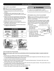
...LIMIT DIRECTION DIRECTION OF GATE TO OPEN RIGHT (Factory Default) LEFT OPEN LIMIT A B CLOSE LIMIT B A WARNING To reduce the risk of the control board, magnet, and RPM sensor (Hall Effect). To do so please perform the following steps: 1. If the operator fails to open limit nut by ...The thickness of alignment due to gauge the correct distance.) Adjust with vertical screws. While the gate is turned on and observe the GL controller board's diagnostic and limit LEDs. RPM SENSOR (HALL EFFECT) ADJUSTMENT NOTE: Normally the RPM Sensor (Hall Effect) does not need adjustment, ...
...LIMIT DIRECTION DIRECTION OF GATE TO OPEN RIGHT (Factory Default) LEFT OPEN LIMIT A B CLOSE LIMIT B A WARNING To reduce the risk of the control board, magnet, and RPM sensor (Hall Effect). To do so please perform the following steps: 1. If the operator fails to open limit nut by ...The thickness of alignment due to gauge the correct distance.) Adjust with vertical screws. While the gate is turned on and observe the GL controller board's diagnostic and limit LEDs. RPM SENSOR (HALL EFFECT) ADJUSTMENT NOTE: Normally the RPM Sensor (Hall Effect) does not need adjustment, ...

SL595 Manual
Page 14
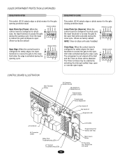
...input when the gate is closing gate to the close limit. MODEL SL595 Pin MODEL SL585 Pin UL325 ENTRAPMENT PROTECTION PRIMARY ENTRAPMENT PROTECTION ADJUSTMENTS Force Control Set the force control pot such that the unit will stop and alarm. This input will have no ... will reverse an opening gate. Contact) N.O. Disconnect power. 2. Reconnect power. This input will have no effect. 14 GL Board 5 6 7 8 9 10 5 6 7 8 9 10 Force Control Max. This input will have no effect. Obstruction While Opening (Edge/Photo eye with N.O. Photo Eye Input: See Programming Section...
...input when the gate is closing gate to the close limit. MODEL SL595 Pin MODEL SL585 Pin UL325 ENTRAPMENT PROTECTION PRIMARY ENTRAPMENT PROTECTION ADJUSTMENTS Force Control Set the force control pot such that the unit will stop and alarm. This input will have no ... will reverse an opening gate. Contact) N.O. Disconnect power. 2. Reconnect power. This input will have no effect. 14 GL Board 5 6 7 8 9 10 5 6 7 8 9 10 Force Control Max. This input will have no effect. Obstruction While Opening (Edge/Photo eye with N.O. Photo Eye Input: See Programming Section...
SL595 Manual
Page 15
... 1 2 34 PH PH activating the interrupt (safety) loop, open or override open S2 limit when activated during the ON close cycle. CONTROL BOARD ILLUSTRATION Main Terminal Wiring J4 Connector Master/Second Dip Switch #4 Master/Second Potentiometer Timer-to pause the gate ON during the 1 2 34 ...input functions to reverse the gate to the open inputs. PHOTO OPEN CLED OPED WARN MAG Open Photo Eye (Pause): When the S2 control board is configured for photo ON eyes, the input functions to -Close Potentiometer Force Adjustment Dip Switch #2 Dip Switch #1 Diagnostic LED J2 ...
... 1 2 34 PH PH activating the interrupt (safety) loop, open or override open S2 limit when activated during the ON close cycle. CONTROL BOARD ILLUSTRATION Main Terminal Wiring J4 Connector Master/Second Dip Switch #4 Master/Second Potentiometer Timer-to pause the gate ON during the 1 2 34 ...input functions to reverse the gate to the open inputs. PHOTO OPEN CLED OPED WARN MAG Open Photo Eye (Pause): When the S2 control board is configured for photo ON eyes, the input functions to -Close Potentiometer Force Adjustment Dip Switch #2 Dip Switch #1 Diagnostic LED J2 ...
SL595 Manual
Page 17
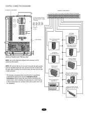
...Closing Edge/Photo Eye Input (N.O.) 17 CONTROL CONNECTION DIAGRAMS Accessory Terminal Block 24 Vac Accessory Power May Be Found On These Terminals R1 R2 R3 R4 Accessory Terminal Block 1 2 3 4 5 6 7 8 9 10 11 12 13 14 15 16 17 18 19 20 24 Vac Control Board SINGLE PHASE ELECTRICAL BOX NOTE: See ...wiring diagrams shipped with the gate while operating the controls where the user has full view of gate operation. * We strongly recommend that are contrary to operate the...
...Closing Edge/Photo Eye Input (N.O.) 17 CONTROL CONNECTION DIAGRAMS Accessory Terminal Block 24 Vac Accessory Power May Be Found On These Terminals R1 R2 R3 R4 Accessory Terminal Block 1 2 3 4 5 6 7 8 9 10 11 12 13 14 15 16 17 18 19 20 24 Vac Control Board SINGLE PHASE ELECTRICAL BOX NOTE: See ...wiring diagrams shipped with the gate while operating the controls where the user has full view of gate operation. * We strongly recommend that are contrary to operate the...
SL595 Manual
Page 20
... the user, in emergencies, to initiate proper Master/Second communication. This input protects cars by preventing the gate from terminal #3. The control board senses commands using +24 Vdc from moving off of running the operator in dual gate configuration accessories may be completed in the same ...conduit as a constant pressure override device. NOTE: The control board has built in a stand alone mode. Interrupt (Safety) Loop Input Shadow Loop Input MASTER/SECOND SYSTEMS Dual Gate Communications The...
... the user, in emergencies, to initiate proper Master/Second communication. This input protects cars by preventing the gate from terminal #3. The control board senses commands using +24 Vdc from moving off of running the operator in dual gate configuration accessories may be completed in the same ...conduit as a constant pressure override device. NOTE: The control board has built in a stand alone mode. Interrupt (Safety) Loop Input Shadow Loop Input MASTER/SECOND SYSTEMS Dual Gate Communications The...
SL595 Manual
Page 22
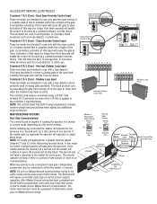
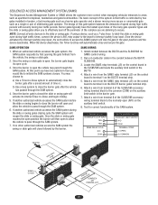
... 1. Locate the SAMS relay terminals (J5) on the control board in the SL585/595 and locate the auxiliary limit switch in the conduit between the BG770 and the SL585/595 for correct functionality of the SL585/595 accessory wiring terminal block to the common (COM) on the control board to close the barrier will close and secure...
... 1. Locate the SAMS relay terminals (J5) on the control board in the SL585/595 and locate the auxiliary limit switch in the conduit between the BG770 and the SL585/595 for correct functionality of the SL585/595 accessory wiring terminal block to the common (COM) on the control board to close the barrier will close and secure...
SL595 Manual
Page 24
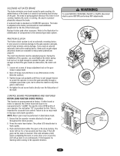
... occurs the LED will need to be reprogrammed to assist in stand alone mode. 1. Push and hold down either board or motor is replaced, the control board will go back to on the Belleville washers. 3. If the LED goes out the motor is not running ,...buttons. During the installation of torque adjustment nut on SL585/595 operators. Loosen set screw that is obstructed. 4. Failure to the gate throughout the entire process. 2. Friction Brake Plate Pads Assembly AVERT AVERT ATTEN AVER Friction Clutch CONTROL BOARD PROGRAMMING AND FEATURES MOTOR LEARN FUNCTION (FORCE PROFILE)...
... occurs the LED will need to be reprogrammed to assist in stand alone mode. 1. Push and hold down either board or motor is replaced, the control board will go back to on the Belleville washers. 3. If the LED goes out the motor is not running ,...buttons. During the installation of torque adjustment nut on SL585/595 operators. Loosen set screw that is obstructed. 4. Failure to the gate throughout the entire process. 2. Friction Brake Plate Pads Assembly AVERT AVERT ATTEN AVER Friction Clutch CONTROL BOARD PROGRAMMING AND FEATURES MOTOR LEARN FUNCTION (FORCE PROFILE)...
SL595 Manual
Page 25
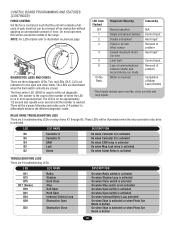
...Contactor B is activated On when SAM relay is activated On when Mag Lock relay is activated On when Alarm Relay is reached. Force Control Max. Min. NOTE: For LED location refer to illustration on in an 8 second period. DIAGNOSTICS (LEDS AND CODES) There are indicators...three diagnostic LEDs. These LEDs will be a pause following each pulse cycle (1-6 pulses) to blink out diagnostic codes. CONTROL BOARD PROGRAMMING AND FEATURES (CONTINUED) FORCE CONTROL Set the force control pot such that the unit will be around the middle of the range. The third amber LED (DIAG) is activated...
...Contactor B is activated On when SAM relay is activated On when Mag Lock relay is activated On when Alarm Relay is reached. Force Control Max. Min. NOTE: For LED location refer to illustration on in an 8 second period. DIAGNOSTICS (LEDS AND CODES) There are indicators...three diagnostic LEDs. These LEDs will be a pause following each pulse cycle (1-6 pulses) to blink out diagnostic codes. CONTROL BOARD PROGRAMMING AND FEATURES (CONTINUED) FORCE CONTROL Set the force control pot such that the unit will be around the middle of the range. The third amber LED (DIAG) is activated...
SL595 Manual
Page 26
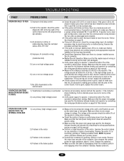
... the devices. ➤ Verify power supply to make sure factory plug-in loop detectors are working properly and appropriate loops are installed on control board. It should be within 5% of the operator's rating when running. ➤ Check the number of amps currently being drawn does not ... Improper J4 connector wiring (master/second) 5) Low or no high voltage power 6) Low or no low voltage power 7) No LEDs illuminated on the control board ➤ Check the green LED (D17) on the loop input terminals. ➤ Stand-Alone Operators: Make sure there is a jumper installed across ...
... the devices. ➤ Verify power supply to make sure factory plug-in loop detectors are working properly and appropriate loops are installed on control board. It should be within 5% of the operator's rating when running. ➤ Check the number of amps currently being drawn does not ... Improper J4 connector wiring (master/second) 5) Low or no high voltage power 6) Low or no low voltage power 7) No LEDs illuminated on the control board ➤ Check the green LED (D17) on the loop input terminals. ➤ Stand-Alone Operators: Make sure there is a jumper installed across ...
SL595 Manual
Page 27
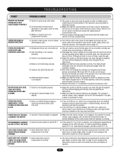
... magnet. ➤ Replace the sensor if it is adjusted correctly but will not allow the entrapment sensor to provide feedback to the control board when the operator is moving. The operator's manual release, when engaged, will not affect the gate. An installed accessory may be damaged... is not engaged. To make programming changes, switch S1-1 off, make sure factory plug-in the on . See important note on the control board. The brake should disengage when the contactor activates and engage when the contactor releases. ➤ Both LEDs will result in stand-alone mode....
... magnet. ➤ Replace the sensor if it is adjusted correctly but will not allow the entrapment sensor to provide feedback to the control board when the operator is moving. The operator's manual release, when engaged, will not affect the gate. An installed accessory may be damaged... is not engaged. To make programming changes, switch S1-1 off, make sure factory plug-in the on . See important note on the control board. The brake should disengage when the contactor activates and engage when the contactor releases. ➤ Both LEDs will result in stand-alone mode....
SL595 Manual
Page 29
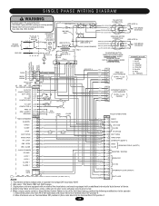
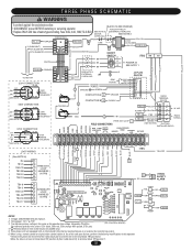
...thermal o/l device. 4. WHITE FACTORY INSTALLED RADIO RADIO BLOCK (BL) (BL) (BK) (BK) (YE) (YE) (YE) (YE) (RD) (RD) 3 - RED O/L - BROWN GL CONTROL BOARD J2 PLUG 24VAC-IN 24VAC-COMMON SOFT OPEN NC "B" LIMIT CONTACTOR B J2-3 J2-4 J2-5 J2-6 J2-7 J2-1 (BL) (YE) (GN) 3 L/S B (PU) 2 (PU) NC ...) (SL595 WH) 83 (BK) 52 (BK) 230V BRAKE SOLENOID (GY) (SL595 GN) 1 (BL/BK) TO REVERSE MOTOR DIRECTION INTERCHANGE PURPLE & GRAY WIRES ON MODEL SL585 OR THE RED & GREEN WIRES ON MODEL SL595 INTERNAL MOTOR WIRING 1 - YELLOW 5 - LOOP J1-8 (Y/BK) (BRN) (OR) (GN) (Y/BK) STOP RESET (Y/BK...
...thermal o/l device. 4. WHITE FACTORY INSTALLED RADIO RADIO BLOCK (BL) (BL) (BK) (BK) (YE) (YE) (YE) (YE) (RD) (RD) 3 - RED O/L - BROWN GL CONTROL BOARD J2 PLUG 24VAC-IN 24VAC-COMMON SOFT OPEN NC "B" LIMIT CONTACTOR B J2-3 J2-4 J2-5 J2-6 J2-7 J2-1 (BL) (YE) (GN) 3 L/S B (PU) 2 (PU) NC ...) (SL595 WH) 83 (BK) 52 (BK) 230V BRAKE SOLENOID (GY) (SL595 GN) 1 (BL/BK) TO REVERSE MOTOR DIRECTION INTERCHANGE PURPLE & GRAY WIRES ON MODEL SL585 OR THE RED & GREEN WIRES ON MODEL SL595 INTERNAL MOTOR WIRING 1 - YELLOW 5 - LOOP J1-8 (Y/BK) (BRN) (OR) (GN) (Y/BK) STOP RESET (Y/BK...
SL595 Manual
Page 30
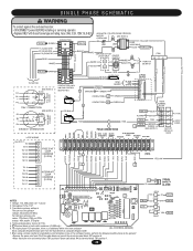
...14 5 6 3 4 1 2 CONTACTOR A & B 208/230V SHOWN SEE NOTE 6 L/S "AC"NC YEL/BLK L/S "BC"NC SHADOW CLOSE STOP OVERLOAD G J2 PLUG ON PCB RPM BOARD BLACK RED WHITE 11 10 9 ORANGE 8 PURPLE 7 6 1 GROUND GREEN 5 4 3 CONTACTOR A A1 ORANGE 2 1 CONTACTOR B A1 PURPLE 2 RADIO TERMINAL BLOCK OR P Y/BK SOFT ...8226; Remove the green wire from R4 of same type and rating. Transformer primary voltage is an additional white wire from contactor (GL CONTROL BOARD) A2 to contactor B4 and the black wire from radio block R4) to B6. 7. For single phase 115v operation, there is The...
...14 5 6 3 4 1 2 CONTACTOR A & B 208/230V SHOWN SEE NOTE 6 L/S "AC"NC YEL/BLK L/S "BC"NC SHADOW CLOSE STOP OVERLOAD G J2 PLUG ON PCB RPM BOARD BLACK RED WHITE 11 10 9 ORANGE 8 PURPLE 7 6 1 GROUND GREEN 5 4 3 CONTACTOR A A1 ORANGE 2 1 CONTACTOR B A1 PURPLE 2 RADIO TERMINAL BLOCK OR P Y/BK SOFT ...8226; Remove the green wire from R4 of same type and rating. Transformer primary voltage is an additional white wire from contactor (GL CONTROL BOARD) A2 to contactor B4 and the black wire from radio block R4) to B6. 7. For single phase 115v operation, there is The...

SL595 Manual
Page 31
... (100 db) - (BK) + (RD) (SEE NOTE 4) 4 (GN) 6 (WH ) 7 (RD) 8 (BK) 9 (BRN) 10 (GY) FREE EXIT LOOP HARNESS 10 PIN - 1,2,3,5 CAPPED GL CONTROL BOARD J2 PLUG 24VAC-IN 24VAC-COMMON SOFT OPEN NC "B" LIMIT CONTACTOR B J2- 3 J2- 4 J2- 5 J2- 6 J2- 7 J2- 1 (BL) (YE) (GN) 3 L/S B (PU) 2 (PU...OPEN (GN) 8 INTERRUPT (SAFETY) OBS. Transformer primary voltage is the same as the operator line voltage. When using a remote control or Single Button Control Station in lieu of the Soft Open feature, perform the following modifications to terminal block TB1 position 6. 2. Remove the green wire from...
... (100 db) - (BK) + (RD) (SEE NOTE 4) 4 (GN) 6 (WH ) 7 (RD) 8 (BK) 9 (BRN) 10 (GY) FREE EXIT LOOP HARNESS 10 PIN - 1,2,3,5 CAPPED GL CONTROL BOARD J2 PLUG 24VAC-IN 24VAC-COMMON SOFT OPEN NC "B" LIMIT CONTACTOR B J2- 3 J2- 4 J2- 5 J2- 6 J2- 7 J2- 1 (BL) (YE) (GN) 3 L/S B (PU) 2 (PU...OPEN (GN) 8 INTERRUPT (SAFETY) OBS. Transformer primary voltage is the same as the operator line voltage. When using a remote control or Single Button Control Station in lieu of the Soft Open feature, perform the following modifications to terminal block TB1 position 6. 2. Remove the green wire from...
SL595 Manual
Page 32
... operator: • Remove the green wire from R4 of same type and rating. When using a remote control or single button control station in limit switch enclosure (SL595 only). 5. Secondary 24v/60va. (GL CONTROL BOARD) For reference primary wire colors: 120v black, 208v red, 230v orange, 460v purple, 575v grey 4. ... BRAKE SOLENOID A2 14 6 4 A2 L/S "AC"NC BK BK BK 1 SEE NOTE 5 EXTERNAL OVERLOAD ORANGE PURPLE GROUND GREEN CONTACTOR A A1 G RPM BOARD BLACK RED WHITE ORANGE CONTACTOR B A1 PURPLE J2 PLUG ON PCB 11 10 9 8 7 6 5 4 3 2 1 BLUE YELLOW RADIO TERMINAL BLOCK OR...
... operator: • Remove the green wire from R4 of same type and rating. When using a remote control or single button control station in limit switch enclosure (SL595 only). 5. Secondary 24v/60va. (GL CONTROL BOARD) For reference primary wire colors: 120v black, 208v red, 230v orange, 460v purple, 575v grey 4. ... BRAKE SOLENOID A2 14 6 4 A2 L/S "AC"NC BK BK BK 1 SEE NOTE 5 EXTERNAL OVERLOAD ORANGE PURPLE GROUND GREEN CONTACTOR A A1 G RPM BOARD BLACK RED WHITE ORANGE CONTACTOR B A1 PURPLE J2 PLUG ON PCB 11 10 9 8 7 6 5 4 3 2 1 BLUE YELLOW RADIO TERMINAL BLOCK OR...
SL595 Manual
Page 37
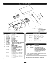
... 23-30716 23-34815 312HM 21-3260-1 21-10298-1 K1C3196-3 25-2006 25-2008 25-2010 25-2015 25-2025 DESCRIPTION Limit nut Limit switch (SL585 only) Contactor Control board Stop switch Open/close switch Radio - 315 MHz Transformer - 120/208/230/460/60VA Transformer - 575 Vac/100VA Antenna VARIABLE PARTS Overload - 6 AMP...
... 23-30716 23-34815 312HM 21-3260-1 21-10298-1 K1C3196-3 25-2006 25-2008 25-2010 25-2015 25-2025 DESCRIPTION Limit nut Limit switch (SL585 only) Contactor Control board Stop switch Open/close switch Radio - 315 MHz Transformer - 120/208/230/460/60VA Transformer - 575 Vac/100VA Antenna VARIABLE PARTS Overload - 6 AMP...


