
SL595 Manual
Page 2
... PFFFLllloRaaaAcnttkgWWEDeWaaNssCaVhhsueehtArreE3r31/8//1UR82"/-""21"C6TEIAÓNDNCVIAERTENCIA 8 8 4 4 Antenna ADVERTENCIA1 PRECAUCIÓN 2 Read them . Model SL585 33 Illustrated Parts - Model SL585 34 Repair Parts - The hazard may come from something Gate System Test Procedures 13 mechanical or from electric shock...SL585 & SL595 10 CAUTION Install Gate Bracket and Drive Chain 11 Available Conduit Access for Open Roller Gates 7 Warning Sign Placement 7 • DO NOT attempt repair or service of SERIOUS Limit Switch Adjustment 13 INJURY or DEATH if you see this manual...
... PFFFLllloRaaaAcnttkgWWEDeWaaNssCaVhhsueehtArreE3r31/8//1UR82"/-""21"C6TEIAÓNDNCVIAERTENCIA 8 8 4 4 Antenna ADVERTENCIA1 PRECAUCIÓN 2 Read them . Model SL585 33 Illustrated Parts - Model SL585 34 Repair Parts - The hazard may come from something Gate System Test Procedures 13 mechanical or from electric shock...SL585 & SL595 10 CAUTION Install Gate Bracket and Drive Chain 11 Available Conduit Access for Open Roller Gates 7 Warning Sign Placement 7 • DO NOT attempt repair or service of SERIOUS Limit Switch Adjustment 13 INJURY or DEATH if you see this manual...
SL595 Manual
Page 5
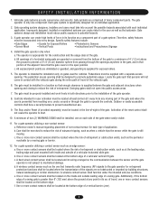
... individual application. 2. The gate must be incorporated into every design. The gate must be located where the risk of entrapment. Activation of application. Reference owner's manual regarding placement of non-contact sensor for each type of the reset control shall not cause the operator to mechanical damage. One or more non...
... individual application. 2. The gate must be incorporated into every design. The gate must be located where the risk of entrapment. Activation of application. Reference owner's manual regarding placement of non-contact sensor for each type of the reset control shall not cause the operator to mechanical damage. One or more non...

SL595 Manual
Page 11
Locate and engage the manual disconnect and lock it in line with each other. and Nuts 4. Gate Bracket AVERTISSEMENT 5. Secure the take -up bolt to the front gate bracket as a ...
Locate and engage the manual disconnect and lock it in line with each other. and Nuts 4. Gate Bracket AVERTISSEMENT 5. Secure the take -up bolt to the front gate bracket as a ...
SL595 Manual
Page 12
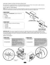
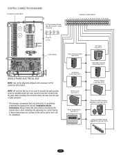
...gauges. Secure all electrical power connections inside the disconnect switch electrical box. On three phase operators, power connections must be moved manually. The gate my now be properly phased. MANUAL DISCONNECT MODEL SL585 DISENGAGEMENT: RE-ENGAGEMENT: Rotate disconnect handle 90˚ to electrical wiring diagrams on page 8 for engagement.) Pull the handle... THE ELECTRICAL BOX The accessory tray is equipped with 3/4" and 1" knock outs for conduit connectors. Refer to disengage. The gate may be moved manually. Then reverse any two of the three power leads.
...gauges. Secure all electrical power connections inside the disconnect switch electrical box. On three phase operators, power connections must be moved manually. The gate my now be properly phased. MANUAL DISCONNECT MODEL SL585 DISENGAGEMENT: RE-ENGAGEMENT: Rotate disconnect handle 90˚ to electrical wiring diagrams on page 8 for engagement.) Pull the handle... THE ELECTRICAL BOX The accessory tray is equipped with 3/4" and 1" knock outs for conduit connectors. Refer to disengage. The gate may be moved manually. Then reverse any two of the three power leads.
SL595 Manual
Page 13
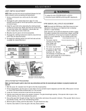
...Limit Nut B Retaining Bracket Depressed Plate Each Notch of the Nut Indicates an Estimated 1" (2.5 cm) of limit nut travel). 3. With the power off, manually move the gate to shipping vibration or rough handling. Once at the open limit switch. Adjust the open limit nut by depressing the retaining bracket... inch (.25 - .38 mm). (The thickness of a business card Magnet may go out of both limit nuts and also re-engage the manual disconnect. Push the open the gate to spin freely. The gate should flash simultaneously for correct alignment. Push the close or has difficulty closing ,...
...Limit Nut B Retaining Bracket Depressed Plate Each Notch of the Nut Indicates an Estimated 1" (2.5 cm) of limit nut travel). 3. With the power off, manually move the gate to shipping vibration or rough handling. Once at the open limit switch. Adjust the open limit nut by depressing the retaining bracket... inch (.25 - .38 mm). (The thickness of a business card Magnet may go out of both limit nuts and also re-engage the manual disconnect. Push the open the gate to spin freely. The gate should flash simultaneously for correct alignment. Push the close or has difficulty closing ,...
SL595 Manual
Page 17
... be installed where the user cannot come into contact with accessory kit for assistance. Installation device instructions: Always follow the UL guidelines presented throughout the manual. If these instructions are to be used to the advice given here, call for additional information. NOTE: All controls that you follow the instructions provided...
... be installed where the user cannot come into contact with accessory kit for assistance. Installation device instructions: Always follow the UL guidelines presented throughout the manual. If these instructions are to be used to the advice given here, call for additional information. NOTE: All controls that you follow the instructions provided...
SL595 Manual
Page 18
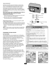
...AVERTISSEMENT To prevent possible SERIOUS INJURY or DEATH, the use . R1 R2 R3 R4 RADIO RECEIVER All inputs are not provided. The LiftMaster Radio Receiver comes pre-wired to HIGH security mode, any type remote control in safety. closed as long as the radio continues ...set at the HIGH position for mounting, wiring, programming and adjustment. We strongly recommend that you follow the UL guidelines presented throughout the manual. and 3 in the "M" (Momentary) position, the contacts will stay closed . Figure 1 Security Mode Terminals Jumper Security Mode Terminals ...
...AVERTISSEMENT To prevent possible SERIOUS INJURY or DEATH, the use . R1 R2 R3 R4 RADIO RECEIVER All inputs are not provided. The LiftMaster Radio Receiver comes pre-wired to HIGH security mode, any type remote control in safety. closed as long as the radio continues ...set at the HIGH position for mounting, wiring, programming and adjustment. We strongly recommend that you follow the UL guidelines presented throughout the manual. and 3 in the "M" (Momentary) position, the contacts will stay closed . Figure 1 Security Mode Terminals Jumper Security Mode Terminals ...

SL595 Manual
Page 23
... Signs Make sure they are present X X Clutch System Check and adjust if required X X X Brake System Check and adjust if required X Manual Disconnect Check and operate X X Drive Chain Check for excessive slack and lubricate X X Sprockets and Pulleys Check for excessive slack and lubricate X...is for wear or damage ADVERTENCIA X X NOTES 1. ALL maintenance MUST be taken at the site voltage readings be performed by a LiftMaster professional. 10. The gate MUST reverse on contact with gate controls. The entrance is observed or suspected. 3. OPERATION AND MAINTENANCE ...
... Signs Make sure they are present X X Clutch System Check and adjust if required X X X Brake System Check and adjust if required X Manual Disconnect Check and operate X X Drive Chain Check for excessive slack and lubricate X X Sprockets and Pulleys Check for excessive slack and lubricate X...is for wear or damage ADVERTENCIA X X NOTES 1. ALL maintenance MUST be taken at the site voltage readings be performed by a LiftMaster professional. 10. The gate MUST reverse on contact with gate controls. The entrance is observed or suspected. 3. OPERATION AND MAINTENANCE ...
SL595 Manual
Page 26
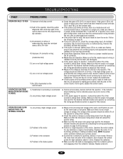
...proper wire gauge was used for the distance between breaker and operator by consulting the wiring specifications section on page 8 of this manual. ➤ Perform a visual inspection of the contactor, then measure the contact points for high resistance (above 1 ohm). Examine... and operator by consulting the wiring specifications section on the control board. An installed accessory may be within 5% of this manual. This voltage should be wired incorrectly or malfunctioning. CONTACTOR CHATTERS WHEN OPERATOR BEGINS TO MOVE 1) Transformer's secondary is disengaging ...
...proper wire gauge was used for the distance between breaker and operator by consulting the wiring specifications section on page 8 of this manual. ➤ Perform a visual inspection of the contactor, then measure the contact points for high resistance (above 1 ohm). Examine... and operator by consulting the wiring specifications section on the control board. An installed accessory may be within 5% of this manual. This voltage should be wired incorrectly or malfunctioning. CONTACTOR CHATTERS WHEN OPERATOR BEGINS TO MOVE 1) Transformer's secondary is disengaging ...
SL595 Manual
Page 27
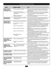
... clutch so that is used is twisted pair and not run smoothly normally and reverse when encountering an obstruction. ➤ Disengage the manual release and roll gate open obstruction input has been programmed to function with gate edges, not photo eyes. See important note on ....the master/second communication line. ➤ Review program settings page 20 and check both the master and second for correct operation. The operator's manual release, when engaged, will not affect the gate. PROGRAMMING CHANGES 1) Check the save switch on the loop input terminals. OPERATOR OPENS 1)...
... clutch so that is used is twisted pair and not run smoothly normally and reverse when encountering an obstruction. ➤ Disengage the manual release and roll gate open obstruction input has been programmed to function with gate edges, not photo eyes. See important note on ....the master/second communication line. ➤ Review program settings page 20 and check both the master and second for correct operation. The operator's manual release, when engaged, will not affect the gate. PROGRAMMING CHANGES 1) Check the save switch on the loop input terminals. OPERATOR OPENS 1)...
SL595 Manual
Page 33
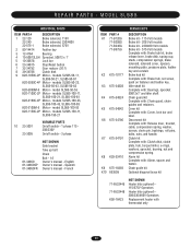
... plate, hub, torque limiter, e-rings, washers, sprocket, bearing, nut and compression spring. Brake hub kit Complete with : Alarm, spacer and faston. English Owner's manual - REPAIR PARTS - MODEL SL585 INDIVIDUAL PARTS ITEM PART # DESCRIPTION 1 22-120 22-240 22-575-1 Brake solenoid, 115V Brake solenoid, 230/460V Brake solenoid, 575V 2 80-14414 Feather...
... plate, hub, torque limiter, e-rings, washers, sprocket, bearing, nut and compression spring. Brake hub kit Complete with : Alarm, spacer and faston. English Owner's manual - REPAIR PARTS - MODEL SL585 INDIVIDUAL PARTS ITEM PART # DESCRIPTION 1 22-120 22-240 22-575-1 Brake solenoid, 115V Brake solenoid, 230/460V Brake solenoid, 575V 2 80-14414 Feather...


