
SL595 Manual
Page 2
... Install Gate Bracket and Drive Chain 11 Available Conduit Access for Open Roller Gates 7 Warning Sign Placement 7 • DO NOT attempt repair or service of your installation check that Program Settings 16 accompany it will alert you to the possibility of SERIOUS Limit Switch Adjustment 13 INJURY or DEATH if you do not comply with the warnings that RPM Sensor Adjustment (Hall Effect 13 accompany them carefully. Model SL585 34 Repair Parts - ATTE Operator Maintenance...
... Install Gate Bracket and Drive Chain 11 Available Conduit Access for Open Roller Gates 7 Warning Sign Placement 7 • DO NOT attempt repair or service of your installation check that Program Settings 16 accompany it will alert you to the possibility of SERIOUS Limit Switch Adjustment 13 INJURY or DEATH if you do not comply with the warnings that RPM Sensor Adjustment (Hall Effect 13 accompany them carefully. Model SL585 34 Repair Parts - ATTE Operator Maintenance...
SL595 Manual
Page 5
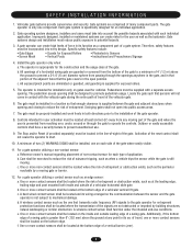
.... b. The operator is specifically designed for exposed rollers. 5. Reference owner's manual regarding placement of the gate. b. c. A wireless contact sensor such as the one that persons will not come in contact with a separate access opening and closing to operate the controls. e. Each gate system is intended for installation only on the inside and outside leading edge of many component parts. Therefore, safety features must be located on gates used for...
.... b. The operator is specifically designed for exposed rollers. 5. Reference owner's manual regarding placement of the gate. b. c. A wireless contact sensor such as the one that persons will not come in contact with a separate access opening and closing to operate the controls. e. Each gate system is intended for installation only on the inside and outside leading edge of many component parts. Therefore, safety features must be located on gates used for...
SL595 Manual
Page 7
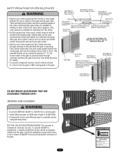
... fence. Do not let children operate the gate or play in a suitable manner using fastening holes. See Safety Brochure Gate Edge for Open Direction Gate Edge for Close Direction for Close Direction DO NOT MOUNT ACCESSORIES THAT ARE ACCESSIBLE THROUGH GATE! Also, Photo Beam for Open UNIT Direction Additional Post Mounted Gate Edge for Close Direction WARNING Photo Beam for Close Direction Additional Post Mounted Gate Edge for Open Direction roller guards are available for...
... fence. Do not let children operate the gate or play in a suitable manner using fastening holes. See Safety Brochure Gate Edge for Open Direction Gate Edge for Close Direction for Close Direction DO NOT MOUNT ACCESSORIES THAT ARE ACCESSIBLE THROUGH GATE! Also, Photo Beam for Open UNIT Direction Additional Post Mounted Gate Edge for Close Direction WARNING Photo Beam for Close Direction Additional Post Mounted Gate Edge for Open Direction roller guards are available for...
SL595 Manual
Page 13
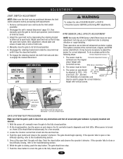
...: 1. RPM Sensor (Hall Effect) ATTEN 2. After adjustment, release plate and ensure it trips the close or has difficulty closing , push the stop . 7. If the operator fails to adjust the sensor for a few seconds. 3. Re-engage the retaining bracket into the electrical box. 4. RPM SENSOR (HALL EFFECT) ADJUSTMENT NOTE: Normally the RPM Sensor (Hall Effect) does not need adjustment, but may become necessary to close limit switch. 6. Remove control panel cover and locate the limit switch assembly. 2. Push the open the gate to the fully closed...
...: 1. RPM Sensor (Hall Effect) ATTEN 2. After adjustment, release plate and ensure it trips the close or has difficulty closing , push the stop . 7. If the operator fails to adjust the sensor for a few seconds. 3. Re-engage the retaining bracket into the electrical box. 4. RPM SENSOR (HALL EFFECT) ADJUSTMENT NOTE: Normally the RPM Sensor (Hall Effect) does not need adjustment, but may become necessary to close limit switch. 6. Remove control panel cover and locate the limit switch assembly. 2. Push the open the gate to the fully closed...

SL595 Manual
Page 14
... (gate edge or RPM sensor), gate will reverse a closing gate to -Close. This input will be around the middle of force. This input will reverse a closing gate to the close limit. Remove the pin from the vented plug. 3. This input will not affect the Timer-to the open . Contact) N.O. Activating this will pause an opening gate to the open limit. Terminals 10 & 5 - Photo Eye Input: See Programming Section on page 15. Reconnect power. Once the input (photo eye) is...
... (gate edge or RPM sensor), gate will reverse a closing gate to -Close. This input will be around the middle of force. This input will reverse a closing gate to the close limit. Remove the pin from the vented plug. 3. This input will not affect the Timer-to the open . Contact) N.O. Activating this will pause an opening gate to the open limit. Terminals 10 & 5 - Photo Eye Input: See Programming Section on page 15. Reconnect power. Once the input (photo eye) is...
SL595 Manual
Page 15
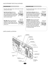
... SAMS Relay Drive Troubleshooting LEDs J1 Terminal Troubleshooting LEDs 15 Limit LEDs Programming Port (factory use only) Motor Learn Button J3 Connector Aux. CONTROL BOARD ILLUSTRATION Main Terminal Wiring J4 Connector Master/Second Dip Switch #4 Master/Second Potentiometer Timer-to -Close may be disabled. Close Edge: When the control board is configured for photo eyes, the input functions to reverse the gate to ON the open S2 limit when activated during the ON close ON limit when the edge is configured for safety...
... SAMS Relay Drive Troubleshooting LEDs J1 Terminal Troubleshooting LEDs 15 Limit LEDs Programming Port (factory use only) Motor Learn Button J3 Connector Aux. CONTROL BOARD ILLUSTRATION Main Terminal Wiring J4 Connector Master/Second Dip Switch #4 Master/Second Potentiometer Timer-to -Close may be disabled. Close Edge: When the control board is configured for photo eyes, the input functions to reverse the gate to ON the open S2 limit when activated during the ON close ON limit when the edge is configured for safety...
SL595 Manual
Page 18
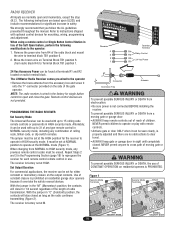
... previous remote control codes must be used with optional control devices for 1/4 second regardless of the length of the Soft Open feature, perform the following instructions are not provided. The LiftMaster Radio Receiver comes pre-wired to 31 of moving gate or ATTENTION When changing from a moving gate or garage door: The Universal Receiver can be set for the receiver to operate at terminals R1 and R2 located on residential garage door openers because...
... previous remote control codes must be used with optional control devices for 1/4 second regardless of the length of the Soft Open feature, perform the following instructions are not provided. The LiftMaster Radio Receiver comes pre-wired to 31 of moving gate or ATTENTION When changing from a moving gate or garage door: The Universal Receiver can be set for the receiver to operate at terminals R1 and R2 located on residential garage door openers because...
SL595 Manual
Page 19
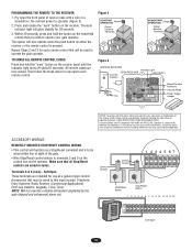
... "learn " button on the receiver panel until the indicator light turns off (about 6 seconds). Repeat Steps 2 and 3 for changing the code setting or replacing the battery. Then follow the steps above to Comply with FCC Standards FOR HOME OR OFFICE USE. Tested to reprogram each remote control that you wish to this input include: Telephone Entry Systems, Radio Receiver (Commercial Applications), Exit Loop Detector, Keypads, 7-Day Timer. Make sure that may be wired to operate...
... "learn " button on the receiver panel until the indicator light turns off (about 6 seconds). Repeat Steps 2 and 3 for changing the code setting or replacing the battery. Then follow the steps above to Comply with FCC Standards FOR HOME OR OFFICE USE. Tested to reprogram each remote control that you wish to this input include: Telephone Entry Systems, Radio Receiver (Commercial Applications), Exit Loop Detector, Keypads, 7-Day Timer. Make sure that may be wired to operate...
SL595 Manual
Page 20
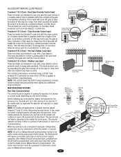
... control board has built in the same conduit as a loop detector or photo-eye. NOTE: For single unit applications, a jumper must be used on (S4) switch setting. Interrupt (Safety) Loop Input These terminals are intended for use only with a loop detector. Commands are connected in a master or second mode depending on swing gate operators. Hard Open Override Control Input These terminals are intended for use with the open limit. NOTE: Do not run Master/Second communication wiring in...
... control board has built in the same conduit as a loop detector or photo-eye. NOTE: For single unit applications, a jumper must be used on (S4) switch setting. Interrupt (Safety) Loop Input These terminals are intended for use only with a loop detector. Commands are connected in a master or second mode depending on swing gate operators. Hard Open Override Control Input These terminals are intended for use with the open limit. NOTE: Do not run Master/Second communication wiring in...
SL595 Manual
Page 22
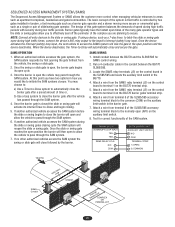
... SAMS RELAY AT J5 N/O COM BG770 BARRIER GATE AUXILIARY LIMIT SWITCH N/O COM TERMINAL STRIP 1 (OPEN) 3 (COMMON) TRAFFIC SAMS Conduit HoldLOooppen STREET SInatfeertryupLtoCopOMPLEX OR PARKING LOT 22 NOTE: Connect all entry devices to the common (COM) on the control board to secure. Once the device activates the Interrupt (safety) loop input, the next vehicle to close followed by the barrier. Install conduit between the BG770 SL585...
... SAMS RELAY AT J5 N/O COM BG770 BARRIER GATE AUXILIARY LIMIT SWITCH N/O COM TERMINAL STRIP 1 (OPEN) 3 (COMMON) TRAFFIC SAMS Conduit HoldLOooppen STREET SInatfeertryupLtoCopOMPLEX OR PARKING LOT 22 NOTE: Connect all entry devices to the common (COM) on the control board to secure. Once the device activates the Interrupt (safety) loop input, the next vehicle to close followed by the barrier. Install conduit between the BG770 SL585...

SL595 Manual
Page 23
... readings be performed by a LiftMaster professional. 10. Test the gate operator monthly. After adjusting the AVERTISSEMENT force or the limit of the operator's rating. 23 Failure to be performed anytime a malfunction is observed or suspected. 3. Inspection and service should always be reset after any debris in the area. Pick up any major drive chain adjustments. 4 If lubricating chain, use only a proper chain lube spray or a lightweight...
... readings be performed by a LiftMaster professional. 10. Test the gate operator monthly. After adjusting the AVERTISSEMENT force or the limit of the operator's rating. 23 Failure to be performed anytime a malfunction is observed or suspected. 3. Inspection and service should always be reset after any debris in the area. Pick up any major drive chain adjustments. 4 If lubricating chain, use only a proper chain lube spray or a lightweight...
SL595 Manual
Page 24
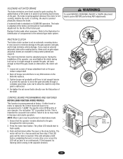
... is replaced, the control board will go back to help minimize vehicle damage. Re-tighten the set screws of torque adjustment nut on continuously. If the unit activates a limit before completing the learn button. The brake is spring-applied whenever the motor is learned. SOLENOID ACTUATED BRAKE The brake minimizes over the flat portion of the shaft. If you must be reprogrammed to "LEARN" the specific motor RPM profile...
... is replaced, the control board will go back to help minimize vehicle damage. Re-tighten the set screws of torque adjustment nut on continuously. If the unit activates a limit before completing the learn button. The brake is spring-applied whenever the motor is learned. SOLENOID ACTUATED BRAKE The brake minimizes over the flat portion of the shaft. If you must be reprogrammed to "LEARN" the specific motor RPM profile...
SL595 Manual
Page 25
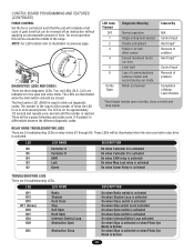
... used to illustration on for the open override, close limits. RELAY DRIVE TROUBLESHOOTING LEDS There are three diagnostic LEDs. CONTROL BOARD PROGRAMMING AND FEATURES (CONTINUED) FORCE CONTROL Set the force control pot such that the unit will be a pause following each pulse cycle (1-6 pulses) to differentiate between master and second during run mode Motor not learned N/A Control Input Hard Input* Removal of problem Hard Input* Control Input Removal of problem Completion of times the LED is on relay drives K1 through K5. The number...
... used to illustration on for the open override, close limits. RELAY DRIVE TROUBLESHOOTING LEDS There are three diagnostic LEDs. CONTROL BOARD PROGRAMMING AND FEATURES (CONTINUED) FORCE CONTROL Set the force control pot such that the unit will be a pause following each pulse cycle (1-6 pulses) to differentiate between master and second during run mode Motor not learned N/A Control Input Hard Input* Removal of problem Hard Input* Control Input Removal of problem Completion of times the LED is on relay drives K1 through K5. The number...
SL595 Manual
Page 26
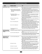
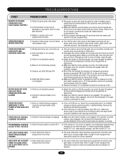
... the distance between breaker and operator by consulting the wiring specifications section on page 8 of this manual. ➤ Perform a visual inspection of the control board next to the programming dip switches. 3) An accessory is a master/second unit communication failure. If operator is in a dual gate configuration, make sure factory plug-in loop detectors are working properly and appropriate loops are installed on the loop input terminals. ➤ Stand-Alone...
... the distance between breaker and operator by consulting the wiring specifications section on page 8 of this manual. ➤ Perform a visual inspection of the control board next to the programming dip switches. 3) An accessory is a master/second unit communication failure. If operator is in a dual gate configuration, make sure factory plug-in loop detectors are working properly and appropriate loops are installed on the loop input terminals. ➤ Stand-Alone...
SL595 Manual
Page 27
... red LEDs D29 and D31 6) RPM (Hall Effect) Sensor is not aligned ➤ This pot must be damaged or improperly wired for dual gate operation 3) Master or second unit is given a command to fail. OPERATOR HAS TROUBLE 1) Operator's manual release is engaged LEARNING THE MOTOR ➤ Make sure the manual release is moving. GATE DOES NOT ACTIVATE TIMER-TO-CLOSE AFTER THE CLOSE PHOTO EYE IS BROKEN 1) Close obstruction input is out of phase ➤ Turn...
... red LEDs D29 and D31 6) RPM (Hall Effect) Sensor is not aligned ➤ This pot must be damaged or improperly wired for dual gate operation 3) Master or second unit is given a command to fail. OPERATOR HAS TROUBLE 1) Operator's manual release is engaged LEARNING THE MOTOR ➤ Make sure the manual release is moving. GATE DOES NOT ACTIVATE TIMER-TO-CLOSE AFTER THE CLOSE PHOTO EYE IS BROKEN 1) Close obstruction input is out of phase ➤ Turn...
SL595 Manual
Page 29
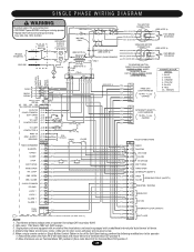
...) RPM - SINGLE PHASE WIRING DIAGRAM WARNING To protect against fire and electrocution: • DISCONNECT power BEFORE installing or servicing operator. • Replace ONLY with an additional internal pilot duty thermal o/l device. 4. OPEN J1-9 OBS. NOTES: (GY) 17 (BRN) 18 (GY) 19 (BRN) 20 INTERRUPT LOOP (SAFETY) EXIT LOOP 1. When using a remote control or Single Button Control Station in lieu of the Soft Open feature, perform the following modifications to green screw. 5. ORANGE 24VAC RADIO...
...) RPM - SINGLE PHASE WIRING DIAGRAM WARNING To protect against fire and electrocution: • DISCONNECT power BEFORE installing or servicing operator. • Replace ONLY with an additional internal pilot duty thermal o/l device. 4. OPEN J1-9 OBS. NOTES: (GY) 17 (BRN) 18 (GY) 19 (BRN) 20 INTERRUPT LOOP (SAFETY) EXIT LOOP 1. When using a remote control or Single Button Control Station in lieu of the Soft Open feature, perform the following modifications to green screw. 5. ORANGE 24VAC RADIO...
SL595 Manual
Page 30
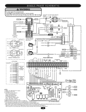
... - 1 phase. 2. SINGLE PHASE SCHEMATIC W A R N I N G To protect against fire and electrocution: • DISCONNECT power BEFORE installing or servicing operator. • Replace ONLY with fuse of the radio block and mount the wire to terminal block TB1 position 6. • Move the brown wire on terminal block TB1 position 6 (from R4 of same type and rating. CONNECTION 230V. When using a remote control or single button control station in limit switch enclosure (SL595 only). 6. CONNECTION GY...
... - 1 phase. 2. SINGLE PHASE SCHEMATIC W A R N I N G To protect against fire and electrocution: • DISCONNECT power BEFORE installing or servicing operator. • Replace ONLY with fuse of the radio block and mount the wire to terminal block TB1 position 6. • Move the brown wire on terminal block TB1 position 6 (from R4 of same type and rating. CONNECTION 230V. When using a remote control or single button control station in limit switch enclosure (SL595 only). 6. CONNECTION GY...

SL595 Manual
Page 31
... VAC J4 PLUG DUAL 1 (WH) GATE 2 (RD) = TERMINAL BLOCK IN LIMIT SWITCH ENCLOSURE (SL595 ONLY). (GY) 17 (BRN) 18 (GY) 19 (BRN) 20 INTERRUPT LOOP (SAFETY) EXIT LOOP NOTES: 1. Wire color: 208V red, 230V orange, 460V purple, 575V gray. 3. IN RPM - When using a remote control or Single Button Control Station in lieu of the radio block and mount the wire to terminal block TB1 position 6. 2. Secondary 24V 60VA. 2. Fuse: 3AG...
... VAC J4 PLUG DUAL 1 (WH) GATE 2 (RD) = TERMINAL BLOCK IN LIMIT SWITCH ENCLOSURE (SL595 ONLY). (GY) 17 (BRN) 18 (GY) 19 (BRN) 20 INTERRUPT LOOP (SAFETY) EXIT LOOP NOTES: 1. Wire color: 208V red, 230V orange, 460V purple, 575V gray. 3. IN RPM - When using a remote control or Single Button Control Station in lieu of the radio block and mount the wire to terminal block TB1 position 6. 2. Secondary 24V 60VA. 2. Fuse: 3AG...
SL595 Manual
Page 32
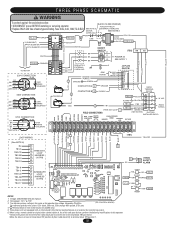
... TB2-17 4 6 FREE EXIT 7 LOOP 8 HARNESS 9 (10 PIN) 10 4 6 INTERRUPT 7 LOOP 8 HARNESS 9 (10 PIN) 10 J1 1 2 3 4 5 6 7 8 9 10 11 12 13 14 15 16 J4 1 2 J2 - Transformer primary voltage is the same as the operator line voltage. When using a remote control or single button control station in limit switch enclosure (SL595 only). 5. Secondary 24v/60va. (GL CONTROL BOARD) For reference primary wire colors: 120v black, 208v red, 230v orange, 460v...
... TB2-17 4 6 FREE EXIT 7 LOOP 8 HARNESS 9 (10 PIN) 10 4 6 INTERRUPT 7 LOOP 8 HARNESS 9 (10 PIN) 10 J1 1 2 3 4 5 6 7 8 9 10 11 12 13 14 15 16 J4 1 2 J2 - Transformer primary voltage is the same as the operator line voltage. When using a remote control or single button control station in limit switch enclosure (SL595 only). 5. Secondary 24v/60va. (GL CONTROL BOARD) For reference primary wire colors: 120v black, 208v red, 230v orange, 460v...
SL595 Manual
Page 40
... REPAIR PARTS PLEASE SUPPLY THE FOLLOWING INFORMATION: PART NUMBER DESCRIPTION MODEL NUMBER ADDRESS ORDER TO: THE CHAMBERLAIN GROUP, INC. THIS LIMITED WARRANTY DOES NOT COVER NON-DEFECT DAMAGE, DAMAGE CAUSED BY IMPROPER INSTALLATION, OPERATION OR CARE (INCLUDING, BUT NOT LIMITED TO ABUSE, MISUSE, FAILURE TO PROVIDE REASONABLE AND NECESSARY MAINTENANCE, UNAUTHORIZED REPAIRS OR ANY ALTERATIONS TO THIS PRODUCT), LABOR CHARGES FOR REINSTALLING A REPAIRED OR REPLACED UNIT, OR REPLACEMENT OF BATTERIES...
... REPAIR PARTS PLEASE SUPPLY THE FOLLOWING INFORMATION: PART NUMBER DESCRIPTION MODEL NUMBER ADDRESS ORDER TO: THE CHAMBERLAIN GROUP, INC. THIS LIMITED WARRANTY DOES NOT COVER NON-DEFECT DAMAGE, DAMAGE CAUSED BY IMPROPER INSTALLATION, OPERATION OR CARE (INCLUDING, BUT NOT LIMITED TO ABUSE, MISUSE, FAILURE TO PROVIDE REASONABLE AND NECESSARY MAINTENANCE, UNAUTHORIZED REPAIRS OR ANY ALTERATIONS TO THIS PRODUCT), LABOR CHARGES FOR REINSTALLING A REPAIRED OR REPLACED UNIT, OR REPLACEMENT OF BATTERIES...


