LiftMaster HDSL24UL Support and Manuals
Get Help and Manuals for this LiftMaster item
View All Support Options Below
Free LiftMaster HDSL24UL manuals!
Problems with LiftMaster HDSL24UL?
Ask a Question
Free LiftMaster HDSL24UL manuals!
Problems with LiftMaster HDSL24UL?
Ask a Question
Most Recent LiftMaster HDSL24UL Questions

Gate Doesn't Open At All
(Posted by Anonymous-171661 1 year ago)
Popular LiftMaster HDSL24UL Manual Pages
LiftMaster HDSL24UL HDSW24UL Wiring Diagram - English French - Page 1

...code itself
(31-99, example" "31"). CODE COLOR KEY: LiftMaster System
Installed System
Informational
CODE NUMBER The second number shown after the code sequence number is the most
recent code (example: "01").
If issue continues, replace main control board... enter limit setup mode and set too tightly against a nonresilient hard stop limit (Arm 1)
Limit may be at boot up to code "20"....
Installation Manual - English - Page 2
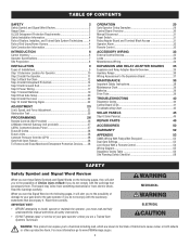
... Safety Instructions 38
Maintenance Chart 39
Batteries 39
Drive Train 39
TROUBLESHOOTING
40
Diagnostic Codes 40
Control Board LEDs 41
Troubleshooting Chart 42
SOLAR PANELS
45
Step 6 Solar Panel(s 45
REPAIR PARTS
49
ACCESSORIES
50
WARRANTY
52
APPENDIX
53
SAMS Wiring With Relays Not Energized 53
Dual Gate Settings 53
Limit Setup With a Remote Control 54
Wiring...
Installation Manual - English - Page 16
...
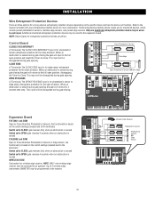
Control Board
CLOSES...functionality is based on the specific device and how the device...settings (located next to the terminals) Switch set to CLOSE: gate reverses fully when an obstruction is sensed Switch set to an operator. NOTE: Board...reverse to each input. INSTALLATION
Wire Entrapment Protection Devices
...will be programmed to the manual included with your entrapment protection...
Installation Manual - English - Page 30

... dual gates. OPERATION
Control Board Overview
1 SET OPEN Button: The SET OPEN button sets the OPEN limit. See Bipart delay/synchronized closed page 21. 6 LEARN Button: The LEARN button is OFF. See Status LED Chart in Limit setting mode. The firmware version will show the operator type, firmware version, and codes. If the TTC is set to CLOSE forces gate...
Installation Manual - English - Page 31

...
The reset switch has the following functions:
• Set the switch to the RESET position to the RESET position. 2.
Reset Switch Manual Release Handle
Relay Adapter Board and Terminal Block Access
To access the relay adapter board and terminal block, loosen the two screws of the control board bracket, slide the whole bracket to the right...
Installation Manual - English - Page 36

...switch positions. After servicing, set all the LEDs will blink out the cycle count, with barrier gate). NOTE: The expansion board will flash the cycle...solar power is between 1,000 and 9,999,000 cycles. If under 1,000 cycles the 1, 2, and 3 LEDs will sound.
N.C.
Energizes when motor is manually tampered with by switch settings. ON
OFF
ON
Energizes if gate is on the control board...
Installation Manual - English - Page 42

... by AC or
solar power or replace batteries d. Replace power board
a. Replace inoperable control board h. c. Use manual disconnect, manually move gate, and ensure gate moves easily limit to a wired control/command (example: open and close inputs for a "stuck on " detector g. Repair gate as needed .
b. Repair gate as needed . b. Set reset switch to control board. Charge batteries by...
Installation Manual - English - Page 51

.... Conveniently plugs into existing control board. Not to be used as entrapment protection. Model MG1300
Heater The heater keeps the gearbox and batteries at a suitable temperature when the outside temperature is installed. Model HTR
Solenoid lock harness kit Model K77-37972 Warning sign Model 40-39235
Long range RFID reader Model LMSC1000
LiftMaster® Internet Gateway Internet...
Installation Manual - English - Page 52

...the date of purchase]. This limited warranty gives you specific legal rights, and you call 1-800-528-2806, toll free, before dismantling this limited warranty, will be repaired or replaced (at Seller's sole option) at Seller's sole option. Parts will be repaired or replaced with the instructions regarding installation, operation, maintenance and testing. Products returned to...
Installation Manual - English - Page 53

..., except entrapment protection devices, and board configurations are set on each operator to the desired setting, see page 24 for more details
Expansion board
ACCESSORY Remote Controls
LiftMaster Internet Gateway Garage and Gate Monitor
PRIMARY OPERATOR
SECONDARY OPERATOR
Program remote controls 1 to 50 to desired OFF Close setting
Bi-Part Delay Switch
Synchronized Close: ON
Synchronized...
LiftMaster Gate Operator Solar Chart - Page 1

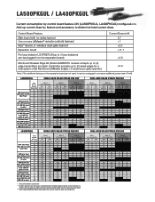
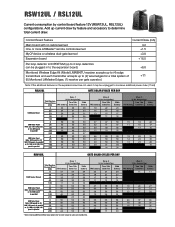
...control board current consumption by feature and accessory, and region of obstructions and shading for the entire day. The batteries are charged from a solar... panel(s) connected to the gate operator via batteries. Snow, heavy fog or heavy rain affect solar panel performance and charge rate. Solar...the operator. SOLAR GATE CYCLES PER DAY REFERENCE GUIDE
LiftMaster Solar Gate Operators...
LiftMaster Gate Operator Solar Chart - Page 2
... LiftMaster Edges, (1) receiver per gate operator.)
+5.8
Note: If the additional features on the expansion board are representative of wired dual-gate installation.
Add up to (4) edge transmitters and each transmitter accepts up current draw by control board feature 24V (LA500PKGUL, LA400PKGUL) configurations. If your installation is a
wireless dual-gate setup use 24V
20
Solar...
LiftMaster Gate Operator Solar Chart - Page 3

... 25 1 #NUM! 57 48 46 17
#NUM! #NUM!
* When installing LMRRUL/LMTBUL heater option refer to install manual for a total system of
+11
(8) Monitored LiftMaster Edges, (1) receiver per gate operator.)
Note: If the additional features on the expansion board are approximations based upon the average solar radiation and the temperature effects on batteries in order to...
LiftMaster Gate Operator Solar Chart - Page 4
.../LMTBUL heater option refer to install manual for a total system of
+11
(8) Monitored LiftMaster Edges, (1) receiver per gate operator.)
Note: If the additional features on the expansion board are not used, it may be unplugged to conserve additional power draw (11mA)
RSL12UL
GATE SOLAR CYCLES PER DAY
Zone 1
(6 Hrs Sunlight/Day)
Total System Current Draw
Two...
LiftMaster Gate Operator Solar Chart - Page 5

... 12V panels or (1) 20W 12V
panel in series
40W Solar Panel Note: 40W would be plugged in to the expansion board)
+3.8
Monitored Wireless Edge Kit (Model LMWEKITU receiver accepts up to (4) edge transmitters and each transmitter accepts up current draw by control board feature 24V (CSW24UL, CSL24UL) configurations.
Zone 3 (2 Hrs Sunlight/Day)
7Ah
33Ah
batteries batteries...
LiftMaster HDSL24UL Reviews
We have not received any reviews for LiftMaster yet.