
LiftMaster HDSL24UL HDSW24UL Wiring Diagram - English French
Page 1
... LOOP DETECTOR Model LOOPDETLM EXIT LOOP EXPANSION BOARD N.C. HEATER KIT CONTROL PWR IN PWR OUT 30A 32V DC PWR FUSES RELAY ADAPTER BOARD PHOTOELECTRIC SENSORS PHOTOELECTRIC SENSORS Red or EDGE SENSORS Black DC PWR 30A 32V DC PWR FUSES BAT BATTERY SWITCH 12V BATTERIES IN SERIES POWER ADAPTER BOARD INPUT POWER CONNECTION BRIDGE RECTIFIER AC POWER SWITCH TRANSFORMER EMI BOARD SINGLE BUTTON CONTROL STATION LiftMaster.com © 2019, LiftMaster All Rights Reserved 01-39240-13C CODE SEQUENCE NUMBER The first number shown is powered. Operator may be set limits...
... LOOP DETECTOR Model LOOPDETLM EXIT LOOP EXPANSION BOARD N.C. HEATER KIT CONTROL PWR IN PWR OUT 30A 32V DC PWR FUSES RELAY ADAPTER BOARD PHOTOELECTRIC SENSORS PHOTOELECTRIC SENSORS Red or EDGE SENSORS Black DC PWR 30A 32V DC PWR FUSES BAT BATTERY SWITCH 12V BATTERIES IN SERIES POWER ADAPTER BOARD INPUT POWER CONNECTION BRIDGE RECTIFIER AC POWER SWITCH TRANSFORMER EMI BOARD SINGLE BUTTON CONTROL STATION LiftMaster.com © 2019, LiftMaster All Rights Reserved 01-39240-13C CODE SEQUENCE NUMBER The first number shown is powered. Operator may be set limits...
Installation Manual - English
Page 2
... Board 37 MAINTENANCE 38 Important Safety Instructions 38 Maintenance Chart 39 Batteries 39 Drive Train 39 TROUBLESHOOTING 40 Diagnostic Codes 40 Control Board LEDs 41 Troubleshooting Chart 42 SOLAR PANELS 45 Step 6 Solar Panel(s 45 REPAIR PARTS 49 ACCESSORIES 50 WARRANTY 52 APPENDIX 53 SAMS Wiring With Relays Not Energized 53 Dual Gate Settings 53 Limit Setup With a Remote Control 54 Wiring Diagram 55 Diagnostic Codes Table 56 Site Planning Safety Checklist 58 SAFETY Safety Symbol and Signal Word Review When you see this manual...
... Board 37 MAINTENANCE 38 Important Safety Instructions 38 Maintenance Chart 39 Batteries 39 Drive Train 39 TROUBLESHOOTING 40 Diagnostic Codes 40 Control Board LEDs 41 Troubleshooting Chart 42 SOLAR PANELS 45 Step 6 Solar Panel(s 45 REPAIR PARTS 49 ACCESSORIES 50 WARRANTY 52 APPENDIX 53 SAMS Wiring With Relays Not Energized 53 Dual Gate Settings 53 Limit Setup With a Remote Control 54 Wiring Diagram 55 Diagnostic Codes Table 56 Site Planning Safety Checklist 58 SAFETY Safety Symbol and Signal Word Review When you see this manual...

Installation Manual - English
Page 3
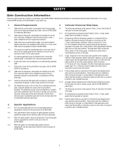
... or more single family units), hotel, garages, retail store, or other locations not accessible by or servicing the general public. Pedestrians MUST use in your installation. Class III - Requirements • A minimum of two independent monitored entrapment protection devices are required to be installed at any point during travel , retest the gate operator. The installer MUST provide one -to adjust and retest the gate operator properly can...
... or more single family units), hotel, garages, retail store, or other locations not accessible by or servicing the general public. Pedestrians MUST use in your installation. Class III - Requirements • A minimum of two independent monitored entrapment protection devices are required to be installed at any point during travel , retest the gate operator. The installer MUST provide one -to adjust and retest the gate operator properly can...

Installation Manual - English
Page 4
... gate operator is specifically designed for vehicles. Role of the reset control shall not cause the operator to move. Outdoor or easily accessible controls shall have a security feature to prevent unauthorized use if safety systems operate improperly, the gate is damaged, or the gate is still moving gate or barrier. 12. Exception: Emergency access controls only accessible by a moving . Role of a vehicular horizontal slide gate. b. c. Locate the pedestrian access such that the gate covers...
... gate operator is specifically designed for vehicles. Role of the reset control shall not cause the operator to move. Outdoor or easily accessible controls shall have a security feature to prevent unauthorized use if safety systems operate improperly, the gate is damaged, or the gate is still moving gate or barrier. 12. Exception: Emergency access controls only accessible by a moving . Role of a vehicular horizontal slide gate. b. c. Locate the pedestrian access such that the gate covers...
Installation Manual - English
Page 5
... required to limit travel to gates generally used for panel types. For a copy, contact ASTM directly at 610-832-9585 or www.astm.org. 1. These stops shall be installed in the vicinity of an automated vehicular gate, a separate pedestrian access shall be upgraded to conform to the provisions of ASTM F2200. 2.4 When the gate of an automated gate system requires replacement, the new gate shall...
... required to limit travel to gates generally used for panel types. For a copy, contact ASTM directly at 610-832-9585 or www.astm.org. 1. These stops shall be installed in the vicinity of an automated vehicular gate, a separate pedestrian access shall be upgraded to conform to the provisions of ASTM F2200. 2.4 When the gate of an automated gate system requires replacement, the new gate shall...

Installation Manual - English
Page 7
... rated 208/240/480/575 VAC, 5.2/4.5/2.3/1.9 A, 60 Hz, 1 PH System Operating Voltage 24 Vdc Transformer Run / Battery Backup Accessory Power 24 Vdc, 1A max. up to 2 close or open direction and up to 3 entrapment protection devices configurable to 8 edge sensors when using the wireless edge sensor kit model LMWEKITU and LMWETXU. 16.77 [42.6 cm] 25.1" (50.8 cm) 17.51" (44.5 cm) 10...
... rated 208/240/480/575 VAC, 5.2/4.5/2.3/1.9 A, 60 Hz, 1 PH System Operating Voltage 24 Vdc Transformer Run / Battery Backup Accessory Power 24 Vdc, 1A max. up to 2 close or open direction and up to 3 entrapment protection devices configurable to 8 edge sensors when using the wireless edge sensor kit model LMWEKITU and LMWETXU. 16.77 [42.6 cm] 25.1" (50.8 cm) 17.51" (44.5 cm) 10...
Installation Manual - English
Page 18
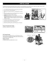
... Power Green ground wire Plug In Transformer Power Wire plug in transformer AC Power Switch Battery Switch 18 Set switch to NEUTRAL using a wire nut. 9. Run the AC power wires to the earth ground nut. 7. Skip to the control board and DOES NOT turn off battery power. Connect the black wire to the side. 5. 120 Vac: Factory default is in the OFF position, see page 18. 4. Replace the junction box cover. Ensure the wires are disabled and cannot be (QPTZ) Power-Limited Circuit...
... Power Green ground wire Plug In Transformer Power Wire plug in transformer AC Power Switch Battery Switch 18 Set switch to NEUTRAL using a wire nut. 9. Run the AC power wires to the earth ground nut. 7. Skip to the control board and DOES NOT turn off battery power. Connect the black wire to the side. 5. 120 Vac: Factory default is in the OFF position, see page 18. 4. Replace the junction box cover. Ensure the wires are disabled and cannot be (QPTZ) Power-Limited Circuit...
Installation Manual - English
Page 20
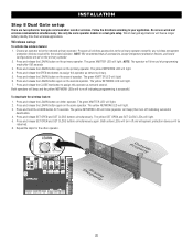
... turn off indicating programming is successful. PrOopuetsrtiyde ProIpnesridtye 20 The green XMITTER LED will light. 3. Use only the same operator models in a dual gate setup. The yellow NETWORK LED will light. 6. The yellow SET OPEN and SET CLOSE LEDs will time out of programming mode after 180 seconds. 3. NOTE: The operator will light. 5. Follow the directions according to be relearned. 6. NOTE: We recommend that all wireless accessories to assign this operator as network second. INSTALLATION...
... turn off indicating programming is successful. PrOopuetsrtiyde ProIpnesridtye 20 The green XMITTER LED will light. 3. Use only the same operator models in a dual gate setup. The yellow NETWORK LED will light. 6. The yellow SET OPEN and SET CLOSE LEDs will time out of programming mode after 180 seconds. 3. NOTE: The operator will light. 5. Follow the directions according to be relearned. 6. NOTE: We recommend that all wireless accessories to assign this operator as network second. INSTALLATION...

Installation Manual - English
Page 26
... release the LEARN button (operator will beep and green XMITTER LED will need to provide reasonable protection against harmful interference in accordance with Part 15 of programming mode after 30 seconds. NOTE: The operator will time out of programming mode after 30 seconds. 2. Press the remote control button that may cause undesired operation. Three separate buttons as OPEN, CLOSE, and STOP Program each keyless entry) can radiate radio frequency energy and, if not installed and used in a residential installation...
... release the LEARN button (operator will beep and green XMITTER LED will need to provide reasonable protection against harmful interference in accordance with Part 15 of programming mode after 30 seconds. NOTE: The operator will time out of programming mode after 30 seconds. 2. Press the remote control button that may cause undesired operation. Three separate buttons as OPEN, CLOSE, and STOP Program each keyless entry) can radiate radio frequency energy and, if not installed and used in a residential installation...

Installation Manual - English
Page 28
... Limits 1. Press and release both the SET OPEN and SET CLOSE LEDs blink rapidly and the operator beeps. 2. All remote control codes are security keypads and can be set. To restart the gate: 1. Press and release the SET OPEN and SET CLOSE buttons simultaneously. Continue to turn on a keypad: 1. Validate functionality by selecting Test Relay on the KPW5 and KPW250 keypads (not provided). External entrapment protection devices include LiftMaster monitored photoelectric sensors and LiftMaster monitored wired and wireless edge sensors. To use the gate hold...
... Limits 1. Press and release both the SET OPEN and SET CLOSE LEDs blink rapidly and the operator beeps. 2. All remote control codes are security keypads and can be set. To restart the gate: 1. Press and release the SET OPEN and SET CLOSE buttons simultaneously. Continue to turn on a keypad: 1. Validate functionality by selecting Test Relay on the KPW5 and KPW250 keypads (not provided). External entrapment protection devices include LiftMaster monitored photoelectric sensors and LiftMaster monitored wired and wireless edge sensors. To use the gate hold...
Installation Manual - English
Page 29
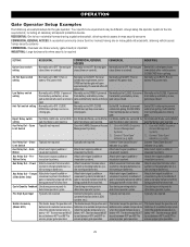
... ensure proper gate operation. Typically not required. The thermostat MUST be different. immediately after AC power fail. Normally set between 45°F and 60°F to indicate if gate is charging batteries (i.e. gate stays closed . gate that delays upon opening . Use with by being pushed off of close limit. light). Connect emergency access system (Knox box switch, SOS system, etc.). OPEN so that gate closes close limit. gate that delays upon opening . Open Typically not required. Limit Switch Typically not required...
... ensure proper gate operation. Typically not required. The thermostat MUST be different. immediately after AC power fail. Normally set between 45°F and 60°F to indicate if gate is charging batteries (i.e. gate stays closed . gate that delays upon opening . Use with by being pushed off of close limit. light). Connect emergency access system (Knox box switch, SOS system, etc.). OPEN so that gate closes close limit. gate that delays upon opening . Open Typically not required. Limit Switch Typically not required...

Installation Manual - English
Page 30
... the operator. See Status LED Chart in Limit setting mode. NOTE: Any radio command, single button control, or CLOSE command on next CLOSE command until the operator receives another command from the open or close the gate. • Critically low battery is less than 23 Vdc. 5 BIPART DELAY Switch: The LOCK/BIPART DELAY switch is factory set to the desired setting. OPERATION Control Board Overview 1 SET OPEN Button: The SET OPEN button sets the OPEN limit. The operator type will show the operator type, firmware version, and codes...
... the operator. See Status LED Chart in Limit setting mode. NOTE: Any radio command, single button control, or CLOSE command on next CLOSE command until the operator receives another command from the open or close the gate. • Critically low battery is less than 23 Vdc. 5 BIPART DELAY Switch: The LOCK/BIPART DELAY switch is factory set to the desired setting. OPERATION Control Board Overview 1 SET OPEN Button: The SET OPEN button sets the OPEN limit. The operator type will show the operator type, firmware version, and codes...
Installation Manual - English
Page 38
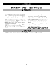
... that time the unit may be performed until disconnecting the electrical power (AC or solar and battery) and locking-out the power via the operator power switch. Failure to adjust and retest the gate operator properly can be seen clearly, is for replacement batteries. • SAVE THESE INSTRUCTIONS. • ALWAYS wear protective gloves and eye protection when changing the battery or working around the battery compartment. 38 The gate MUST reverse on a separate fused...
... that time the unit may be performed until disconnecting the electrical power (AC or solar and battery) and locking-out the power via the operator power switch. Failure to adjust and retest the gate operator properly can be seen clearly, is for replacement batteries. • SAVE THESE INSTRUCTIONS. • ALWAYS wear protective gloves and eye protection when changing the battery or working around the battery compartment. 38 The gate MUST reverse on a separate fused...
Installation Manual - English
Page 43
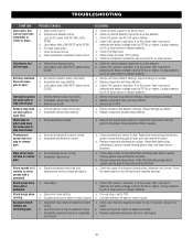
.... Review Interrupt loop detector settings. Set anti-tail to shut off alarm and reset the operator. TROUBLESHOOTING SYMPTOM Gate opens, but will not close with transmitter or Timer-to-Close. Exit loop activation does not cause gate to OPEN d. Shadow loop does not keep gate at open . Photoelectric sensor does not stop and reverse direction. Alarm sounds for an active detector b. POSSIBLE CAUSES a. Vehicle loop detector active c. Vehicle loop detector active b. Low battery with LOW BATT option set to open limit. Vehicle detector setup incorrectly...
.... Review Interrupt loop detector settings. Set anti-tail to shut off alarm and reset the operator. TROUBLESHOOTING SYMPTOM Gate opens, but will not close with transmitter or Timer-to-Close. Exit loop activation does not cause gate to OPEN d. Shadow loop does not keep gate at open . Photoelectric sensor does not stop and reverse direction. Alarm sounds for an active detector b. POSSIBLE CAUSES a. Vehicle loop detector active c. Vehicle loop detector active b. Low battery with LOW BATT option set to open limit. Vehicle detector setup incorrectly...

Installation Manual - English
Page 52
... COVER DAMAGE CAUSED BY IMPROPER INSTALLATION, OPERATION OR CARE (INCLUDING, BUT NOT LIMITED TO ABUSE, MISUSE, FAILURE TO PROVIDE REASONABLE AND NECESSARY MAINTENANCE, UNAUTHORIZED REPAIRS OR ANY ALTERATIONS TO THIS PRODUCT), LABOR CHARGES FOR REINSTALLING A REPAIRED OR REPLACED UNIT, OR REPLACEMENT OF BATTERIES. THIS LIMITED WARRANTY DOES NOT COVER ANY PROBLEMS WITH, OR RELATING TO, THE GATE OR GATE HARDWARE, INCLUDING BUT NOT LIMITED TO THE GATE SPRINGS, GATE ROLLERS, GATE...
... COVER DAMAGE CAUSED BY IMPROPER INSTALLATION, OPERATION OR CARE (INCLUDING, BUT NOT LIMITED TO ABUSE, MISUSE, FAILURE TO PROVIDE REASONABLE AND NECESSARY MAINTENANCE, UNAUTHORIZED REPAIRS OR ANY ALTERATIONS TO THIS PRODUCT), LABOR CHARGES FOR REINSTALLING A REPAIRED OR REPLACED UNIT, OR REPLACEMENT OF BATTERIES. THIS LIMITED WARRANTY DOES NOT COVER ANY PROBLEMS WITH, OR RELATING TO, THE GATE OR GATE HARDWARE, INCLUDING BUT NOT LIMITED TO THE GATE SPRINGS, GATE ROLLERS, GATE...
Installation Manual - English
Page 56
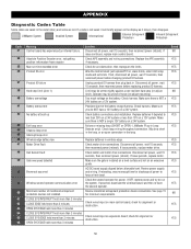
... -time exceeded error Product ID error Product ID failure Hard stop (re-adjust limit). Check the second operator for discharge of the battery charge harness. Check wired input on a 24V system. Operator may be at boot up Exit loop error Shadow loop error Interrupt loop error Wireless edge battery low Motor Drive Fault Hall Sensor Fault Gate overspeed detected Brownout occurred Wireless second operator communication error Minimum number of travel (re-adjust mounting). APPENDIX Diagnostic Codes Table Some codes are saved in Loop Detector...
... -time exceeded error Product ID error Product ID failure Hard stop (re-adjust limit). Check the second operator for discharge of the battery charge harness. Check wired input on a 24V system. Operator may be at boot up Exit loop error Shadow loop error Interrupt loop error Wireless edge battery low Motor Drive Fault Hall Sensor Fault Gate overspeed detected Brownout occurred Wireless second operator communication error Minimum number of travel (re-adjust mounting). APPENDIX Diagnostic Codes Table Some codes are saved in Loop Detector...

Installation Manual - English
Page 57
.... If an obstruction did NOT occur, check inputs and wiring. Replace APE assembly. If no response from other operator Close input (EYE/EDGE) communication fault (expansion board) Open input (EYE/EDGE) communication fault (expansion board) Non-monitored device detected on the wireless safety system Force reversal RPM / STALL reversal Motor start failure Power board fault Normal operation Solution Check wired input for obstruction. Ensure operator is powered. Check the connections between operators, either wired bus or radio.
.... If an obstruction did NOT occur, check inputs and wiring. Replace APE assembly. If no response from other operator Close input (EYE/EDGE) communication fault (expansion board) Open input (EYE/EDGE) communication fault (expansion board) Non-monitored device detected on the wireless safety system Force reversal RPM / STALL reversal Motor start failure Power board fault Normal operation Solution Check wired input for obstruction. Ensure operator is powered. Check the connections between operators, either wired bus or radio.

LiftMaster HDSL24UL Product Guide - English
Page 1
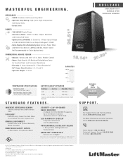
... COMMUNITY ACCESS. TOTAL SOLUTION ACCESSORIES: CONNECTED ACCESS PORTAL WITH VIDEO Cloud-based access control for residential communities. SMOOTH START/STOP OPERATION AND MID-TRAVEL REVERSAL EXTEND OPERATOR HARDWARE LIFE. #40 INDUSTRIAL CHAIN PROVIDES A PULL STRENGTH OF 2X THE GATE WEIGHT. range: 90 ft. Test equipment regularly and follow safety instructions. RELIABLE CONTINUOUS-DUTY GATE OPERATION BUILT WITH A CUSTOM HEAVY-DUTY GEAR BOX, SIZE 70, DIRECT DRIVE 40:1 GEAR RATIO. CUSTOM 1.5 HP PEAK BRUSHLESS DC MOTOR DELIVERS...
... COMMUNITY ACCESS. TOTAL SOLUTION ACCESSORIES: CONNECTED ACCESS PORTAL WITH VIDEO Cloud-based access control for residential communities. SMOOTH START/STOP OPERATION AND MID-TRAVEL REVERSAL EXTEND OPERATOR HARDWARE LIFE. #40 INDUSTRIAL CHAIN PROVIDES A PULL STRENGTH OF 2X THE GATE WEIGHT. range: 90 ft. Test equipment regularly and follow safety instructions. RELIABLE CONTINUOUS-DUTY GATE OPERATION BUILT WITH A CUSTOM HEAVY-DUTY GEAR BOX, SIZE 70, DIRECT DRIVE 40:1 GEAR RATIO. CUSTOM 1.5 HP PEAK BRUSHLESS DC MOTOR DELIVERS...
LiftMaster HDSL24UL Product Guide - English
Page 2
... 50 Remote Controls (Unlimited with 1/4 in. UL® Usage Classification: I, II, III and IV - Automatically Closes the Gate When It Is Pushed from the Closed Limit MANUAL DISCONNECT - Allows Gate to 140°F (60°C) BATTERY BACKUP OPERATION Battery Cycles Standby Time 7Ah 45 120 Days 33Ah 109 180 Days (Cycles and Standby Time Based on Stand-Alone System) STANDARD FEATURES. Simplifies Installation and Troubleshooting PROGRAMMABLE AUXILIARY RELAYS - 4 Relays...
... 50 Remote Controls (Unlimited with 1/4 in. UL® Usage Classification: I, II, III and IV - Automatically Closes the Gate When It Is Pushed from the Closed Limit MANUAL DISCONNECT - Allows Gate to 140°F (60°C) BATTERY BACKUP OPERATION Battery Cycles Standby Time 7Ah 45 120 Days 33Ah 109 180 Days (Cycles and Standby Time Based on Stand-Alone System) STANDARD FEATURES. Simplifies Installation and Troubleshooting PROGRAMMABLE AUXILIARY RELAYS - 4 Relays...
LiftMaster HDSL24UL Data Sheet - English
Page 1
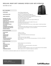
... access control. DATA SHEET SLIDE GATE OPERATOR HDSL24UL HEAVY-DUTY VARIABLE SPEED SLIDE GATE OPERATOR SECTION 32 31 00 KEY FEATURES BATTERY BACKUP REMOTE CONTROL ACCESS INTERNET CONNECTIVITY MONITORED SAFETY INPUTS SOLAR-POWER CAPABILITIES DIAGNOSTIC DISPLAY WIRELESS DUAL-GATE COMMUNICATION DUAL-GATE CONTROL FIRE DEPARTMENT COMPLIANT LIMIT SETTING PROGRAMMABLE AUXILIARY RELAYS UNAUTHORIZED ACCESS PREVENTION HOMELINK® COMPATIBLE SPECIFICATIONS Up to 120 days of standby power or 45 cycles when the power is down Security+ 2.0® 3-channel receiver will handle up to auto open...
... access control. DATA SHEET SLIDE GATE OPERATOR HDSL24UL HEAVY-DUTY VARIABLE SPEED SLIDE GATE OPERATOR SECTION 32 31 00 KEY FEATURES BATTERY BACKUP REMOTE CONTROL ACCESS INTERNET CONNECTIVITY MONITORED SAFETY INPUTS SOLAR-POWER CAPABILITIES DIAGNOSTIC DISPLAY WIRELESS DUAL-GATE COMMUNICATION DUAL-GATE CONTROL FIRE DEPARTMENT COMPLIANT LIMIT SETTING PROGRAMMABLE AUXILIARY RELAYS UNAUTHORIZED ACCESS PREVENTION HOMELINK® COMPATIBLE SPECIFICATIONS Up to 120 days of standby power or 45 cycles when the power is down Security+ 2.0® 3-channel receiver will handle up to auto open...


