
SL595 Manual
Page 2
...Hall Effect 13 accompany them carefully. OPERATOR WARNINGS Safety Installation Information 5 Suggested Entrapment Protection Device Locations 6 Safety Precautions for Open Roller Gates 7 Warning Sign Placement 7 • DO NOT attempt repair or service of SERIOUS Limit Switch Adjustment 13 INJURY or...MAINTENANCE for factory provided parts. ATTE Operator Maintenance 23 AVERTISSEMENT Solenoid Actuated Brake 24 Friction Clutch 24 HARDWARE KIT SL585/SL595 (K77-34846) Control Board Programming and Features 24-25 AVER Troubleshooting 26-27 Self-Regulating Heater Accessory...
...Hall Effect 13 accompany them carefully. OPERATOR WARNINGS Safety Installation Information 5 Suggested Entrapment Protection Device Locations 6 Safety Precautions for Open Roller Gates 7 Warning Sign Placement 7 • DO NOT attempt repair or service of SERIOUS Limit Switch Adjustment 13 INJURY or...MAINTENANCE for factory provided parts. ATTE Operator Maintenance 23 AVERTISSEMENT Solenoid Actuated Brake 24 Friction Clutch 24 HARDWARE KIT SL585/SL595 (K77-34846) Control Board Programming and Features 24-25 AVER Troubleshooting 26-27 Self-Regulating Heater Accessory...

SL595 Manual
Page 3
OPERATOR DIMENSIONS AND HORSEPOWER CHART MODEL SL585 • 1/2 HP Motor Maximum Gate Speed - 11"/sec. (27.9 cm/sec.) Maximum Gate Weight - 1000 lbs. (453.6 kg) Maximum Cantilever Gate Width - 25 ft. (7.6 m) Maximum Overhead Roller Gate Width - 45 ft. (13.7 m) Maximum V-Track Gate Width - 35 ft. (10.7 m) 28.9" (73.4 cm)... kg) Maximum Cantilever Gate Width - 45 ft. (13.7 m) Maximum Overhead Roller Gate Width - 90 ft. (27.4 m) Maximum V-Track Gate Width - 60 ft. (18.3 m) 24" (61 cm) Gate Side 16.5" (41.9 cm) 13.5" (34.3 cm) 22.5" (57.2 cm) 30" (76.2 cm) Allow For Door Opening 12" Min. (30...
OPERATOR DIMENSIONS AND HORSEPOWER CHART MODEL SL585 • 1/2 HP Motor Maximum Gate Speed - 11"/sec. (27.9 cm/sec.) Maximum Gate Weight - 1000 lbs. (453.6 kg) Maximum Cantilever Gate Width - 25 ft. (7.6 m) Maximum Overhead Roller Gate Width - 45 ft. (13.7 m) Maximum V-Track Gate Width - 35 ft. (10.7 m) 28.9" (73.4 cm)... kg) Maximum Cantilever Gate Width - 45 ft. (13.7 m) Maximum Overhead Roller Gate Width - 90 ft. (27.4 m) Maximum V-Track Gate Width - 60 ft. (18.3 m) 24" (61 cm) Gate Side 16.5" (41.9 cm) 13.5" (34.3 cm) 22.5" (57.2 cm) 30" (76.2 cm) Allow For Door Opening 12" Min. (30...
SL595 Manual
Page 4
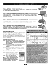
... Both primary and secondary entrapment protection methods must sense and initiate the reverse of the gate within the operator. SAFETY ACCESSORY SELECTION All UL325 compliant LiftMaster gate operators will accept external entrapment protection devices to service the general public. ENTRAPMENT PROTECTION TYPES... time without prior warning. CLASS IV - COMMERCIAL/GENERAL ACCESS VEHICULAR GATE OPERATOR A vehicular gate operator (or system) intended for use in which unauthorized access is installed on both the open and close directions of the four UL325 classes. In order to...
... Both primary and secondary entrapment protection methods must sense and initiate the reverse of the gate within the operator. SAFETY ACCESSORY SELECTION All UL325 compliant LiftMaster gate operators will accept external entrapment protection devices to service the general public. ENTRAPMENT PROTECTION TYPES... time without prior warning. CLASS IV - COMMERCIAL/GENERAL ACCESS VEHICULAR GATE OPERATOR A vehicular gate operator (or system) intended for use in which unauthorized access is installed on both the open and close directions of the four UL325 classes. In order to...
SL595 Manual
Page 5
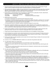
... reachable by building structures, natural landscaping or similar obstruction. A wireless contact sensor such as the bystander. Install the gate operator only when: a. Pedestrians must be located at any moving . Swinging gates shall not open position. Controls intended for the user as well as the one or more contact sensors shall be designed to...
... reachable by building structures, natural landscaping or similar obstruction. A wireless contact sensor such as the bystander. Install the gate operator only when: a. Pedestrians must be located at any moving . Swinging gates shall not open position. Controls intended for the user as well as the one or more contact sensors shall be designed to...

SL595 Manual
Page 6
SUGGESTED ENTRAPMENT PROTECTION DEVICE LOCATIONS GATE SYSTEM (MASTER/SECOND SLIDE GATE) Open Edge Gate 2 Open Edge STREET Photo eyes for close cycle Gate 1 Close Edge Photo eyes for open cycle Run twisted wire from loop to operator Interrupt (Safety) Loop 4'T(y1p.2icmal) 4'T(y1p.2icmal) Interrupt (...mm) Loop wire layer 1/4" (6 mm) or larger depending on loop wire size Photo eyes for open cycle GATE SYSTEM (COMMERCIAL SLIDE GATE) Telephone Entry System Open Edge Close Edge Photo eye for open cycle STREET 8' (2.4Inmt(eS)rarLufoepottyp) Photo eye for close cycle 4' (1.2 m) Typical 4' (...
SUGGESTED ENTRAPMENT PROTECTION DEVICE LOCATIONS GATE SYSTEM (MASTER/SECOND SLIDE GATE) Open Edge Gate 2 Open Edge STREET Photo eyes for close cycle Gate 1 Close Edge Photo eyes for open cycle Run twisted wire from loop to operator Interrupt (Safety) Loop 4'T(y1p.2icmal) 4'T(y1p.2icmal) Interrupt (...mm) Loop wire layer 1/4" (6 mm) or larger depending on loop wire size Photo eyes for open cycle GATE SYSTEM (COMMERCIAL SLIDE GATE) Telephone Entry System Open Edge Close Edge Photo eye for open cycle STREET 8' (2.4Inmt(eS)rarLufoepottyp) Photo eye for close cycle 4' (1.2 m) Typical 4' (...
SL595 Manual
Page 7
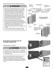
... or Death KEEP CLEAR! Do not let children operate the gate or play in a suitable manner using fastening holes. SAFETY PRECAUTIONS FOR OPEN ROLLER GATES WARNING Gate Edge on Rear of Gate for Open Direction Gate Edge on Fence Post for Open Direction Gate Edge on WARNING Leading Edge of Gate for Close Direction • Injuries occur when people get...
... or Death KEEP CLEAR! Do not let children operate the gate or play in a suitable manner using fastening holes. SAFETY PRECAUTIONS FOR OPEN ROLLER GATES WARNING Gate Edge on Rear of Gate for Open Direction Gate Edge on Fence Post for Open Direction Gate Edge on WARNING Leading Edge of Gate for Close Direction • Injuries occur when people get...

SL595 Manual
Page 11
Remove the operator cover or open access door. 2" (5.1 cm) U-bolts With Lock Washers AVERTISSEMENT 3. Connect chain take -up bolt to the end of the chain and attach to page 12). Gate Bracket AVERTISSEMENT 5. Figure 1 WARNING Gate "Outside" "Inside" WARNING 1. Locate and engage the...) actuators on chain take -up bolts to the vertical front and rear posts of the gate (Figure 1). 2. PRECAUCIÓN Figure 3 Gate Bracket Drive Sprocket Gate Post ADVERTENCIA Idler Sprocket Idler Sprocket Insert Chain Through Plastic Guides Safety Bracket 11 AVERTISSEMENT Adjust ...
Remove the operator cover or open access door. 2" (5.1 cm) U-bolts With Lock Washers AVERTISSEMENT 3. Connect chain take -up bolt to the end of the chain and attach to page 12). Gate Bracket AVERTISSEMENT 5. Figure 1 WARNING Gate "Outside" "Inside" WARNING 1. Locate and engage the...) actuators on chain take -up bolts to the vertical front and rear posts of the gate (Figure 1). 2. PRECAUCIÓN Figure 3 Gate Bracket Drive Sprocket Gate Post ADVERTENCIA Idler Sprocket Idler Sprocket Insert Chain Through Plastic Guides Safety Bracket 11 AVERTISSEMENT Adjust ...
SL595 Manual
Page 12
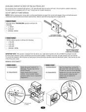
...8 for correct wire gauges. On three phase operators, power connections must be required for engagement.) MODEL SL595 DISENGAGEMENT: RE-ENGAGEMENT: Open the hinged door and pull the disconnect lever and lock it in place. Secure all electrical power connections inside the disconnect switch electrical... Pull the handle to disengage. Refer to wiring specifications on pages 29-32. MANUAL DISCONNECT MODEL SL585 DISENGAGEMENT: RE-ENGAGEMENT: Rotate disconnect handle 90˚ to release 12 The gate may be moved manually. The electrical box is shipped from the factory as 3/4" and 1" knock...
...8 for correct wire gauges. On three phase operators, power connections must be required for engagement.) MODEL SL595 DISENGAGEMENT: RE-ENGAGEMENT: Open the hinged door and pull the disconnect lever and lock it in place. Secure all electrical power connections inside the disconnect switch electrical... Pull the handle to disengage. Refer to wiring specifications on pages 29-32. MANUAL DISCONNECT MODEL SL585 DISENGAGEMENT: RE-ENGAGEMENT: Rotate disconnect handle 90˚ to release 12 The gate may be moved manually. The electrical box is shipped from the factory as 3/4" and 1" knock...
SL595 Manual
Page 13
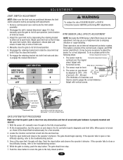
... operator fails to close limit switch. 6. If the operator fails to open limit, the gate will stop. The gate should begin opening , refer to shipping vibration or rough handling. LIMIT DIRECTION DIRECTION OF GATE TO OPEN RIGHT (Factory Default) LEFT OPEN LIMIT A B CLOSE LIMIT B A WARNING To reduce the risk of... the close or has difficulty closing , push the stop . 7. The sensor must be used to spin freely. Adjust open limit nut so that all associated gate hardware is closing , refer to the fully closed position. 13 AVER Limit Switch Limit Nut A Limit Switch Limit Nut ...
... operator fails to close limit switch. 6. If the operator fails to open limit, the gate will stop. The gate should begin opening , refer to shipping vibration or rough handling. LIMIT DIRECTION DIRECTION OF GATE TO OPEN RIGHT (Factory Default) LEFT OPEN LIMIT A B CLOSE LIMIT B A WARNING To reduce the risk of... the close or has difficulty closing , push the stop . 7. The sensor must be used to spin freely. Adjust open limit nut so that all associated gate hardware is closing , refer to the fully closed position. 13 AVER Limit Switch Limit Nut A Limit Switch Limit Nut ...

SL595 Manual
Page 14
... be around the middle of force. MODEL SL595 Pin MODEL SL585 Pin UL325 ENTRAPMENT PROTECTION PRIMARY ENTRAPMENT PROTECTION ADJUSTMENTS Force Control Set the force control pot such that the unit will pause an opening gate to -Close. Activating this input when the gate is closing will not affect the Timer-to the close limit...
... be around the middle of force. MODEL SL595 Pin MODEL SL585 Pin UL325 ENTRAPMENT PROTECTION PRIMARY ENTRAPMENT PROTECTION ADJUSTMENTS Force Control Set the force control pot such that the unit will pause an opening gate to -Close. Activating this input when the gate is closing will not affect the Timer-to the close limit...
SL595 Manual
Page 15
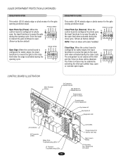
...safety edges, the input EDGE CLOSE CLED OPED WARN MAG functions to reverse the gate to pause the gate ON during the 1 2 34 PH PH opening protection input. EDGE OPEN CLED OPED WARN MAG Open Edge: When the control board is S2 configured for safety edges, the input ... (factory use only) Motor Learn Button J3 Connector Aux. UL325 ENTRAPMENT PROTECTION (CONTINUED) EDGE/PHOTO OPEN This switch (S2-3) selects edge or photo sensor for the gate opening cycle. PHOTO OPEN CLED OPED WARN MAG Open Photo Eye (Pause): When the S2 control board is activated during the...
...safety edges, the input EDGE CLOSE CLED OPED WARN MAG functions to reverse the gate to pause the gate ON during the 1 2 34 PH PH opening protection input. EDGE OPEN CLED OPED WARN MAG Open Edge: When the control board is S2 configured for safety edges, the input ... (factory use only) Motor Learn Button J3 Connector Aux. UL325 ENTRAPMENT PROTECTION (CONTINUED) EDGE/PHOTO OPEN This switch (S2-3) selects edge or photo sensor for the gate opening cycle. PHOTO OPEN CLED OPED WARN MAG Open Photo Eye (Pause): When the S2 control board is activated during the...

SL595 Manual
Page 16
...TO-CLOSE ENABLE TIMER-TO-CLOSE This switch enables the auto close timer. SL = Slide • SW = Swing RIGHT/LEFT OPERATION This switch selects the gate opening direction, to the left or to the off position. PROGRAM SETTINGS (DIP SWITCH S2) Max. = 180 sec Min. = 0 sec TTC TTC TTC ... feature works in motion" alarm feature. When switch is determined from the inside of fence looking out. On an open command there will beep 3 seconds prior to optimize gate behavior for specific application. NOTE: For any programming changes to take effect, the Save Mode switch must be in ...
...TO-CLOSE ENABLE TIMER-TO-CLOSE This switch enables the auto close timer. SL = Slide • SW = Swing RIGHT/LEFT OPERATION This switch selects the gate opening direction, to the left or to the off position. PROGRAM SETTINGS (DIP SWITCH S2) Max. = 180 sec Min. = 0 sec TTC TTC TTC ... feature works in motion" alarm feature. When switch is determined from the inside of fence looking out. On an open command there will beep 3 seconds prior to optimize gate behavior for specific application. NOTE: For any programming changes to take effect, the Save Mode switch must be in ...
SL595 Manual
Page 17
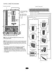
... STOP Shadow Loop Input (N.O.) Radio (Single Button) Input (N.O.) FREQ FREQ Soft Open Input (N.O.) 123 56 789 0# Hard Open Override Control Input (N.O.) OPEN CLOSE STOP Interrupt (Safety) Loop Input (N.O.) Obstruction While Opening Edge/Photo Eye Input (N.O.) Obstruction While Closing Edge/Photo Eye Input (N.O.) 17 If these...SINGLE PHASE ELECTRICAL BOX NOTE: See wiring diagrams shipped with the gate while operating the controls where the user has full view of gate operation. * We strongly recommend that are contrary to operate the gate system, must be used to the advice given here, call...
... STOP Shadow Loop Input (N.O.) Radio (Single Button) Input (N.O.) FREQ FREQ Soft Open Input (N.O.) 123 56 789 0# Hard Open Override Control Input (N.O.) OPEN CLOSE STOP Interrupt (Safety) Loop Input (N.O.) Obstruction While Opening Edge/Photo Eye Input (N.O.) Obstruction While Closing Edge/Photo Eye Input (N.O.) 17 If these...SINGLE PHASE ELECTRICAL BOX NOTE: See wiring diagrams shipped with the gate while operating the controls where the user has full view of gate operation. * We strongly recommend that are contrary to operate the gate system, must be used to the advice given here, call...
SL595 Manual
Page 18
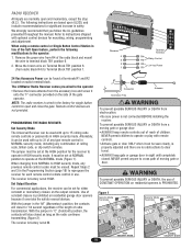
... keep remote controls out of reach of any type remote control in "C" (Constant) position, the contacts will close the gate. Move the brown wire on residential openers is factory set at the NORMAL mode (Figure 1). closed as long as the radio continues transmitting (Figure 2). The receiver... the accessary box and screw it can be used with optional control devices for each remote control remote control in safety. The LiftMaster Radio Receiver comes pre-wired to the operator WARNING • Remove the brass antenna from electrocution: PROGRAMMING THE RADIO RECEIVER Set ...
... keep remote controls out of reach of any type remote control in "C" (Constant) position, the contacts will close the gate. Move the brown wire on residential openers is factory set at the NORMAL mode (Figure 1). closed as long as the radio continues transmitting (Figure 2). The receiver... the accessary box and screw it can be used with optional control devices for each remote control remote control in safety. The LiftMaster Radio Receiver comes pre-wired to the operator WARNING • Remove the brass antenna from electrocution: PROGRAMMING THE RADIO RECEIVER Set ...
SL595 Manual
Page 19
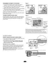
... 9 10 11 12 13 14 123 56 789 0# Soft Open 19 M HIGH NORM M PROGRAMMING THE REMOTE TO THE RECEIVER 1. Operation is to be used to operate your gate operator. NOTE: Will not override a double entrapment (signalled by the gate stopped and entrapment alarm on the hand-held remote that may...Terminals 6 & 5 (Com) - TO ERASE ALL REMOTE CONTROL CODES Press and hold the button on ). The opener will function as a general open the front panel of the gate. • Wire Stop/Reset control station to Comply with a coin or a screwdriver. ACCESSORY WIRING REMOTELY MOUNTED STOP...
... 9 10 11 12 13 14 123 56 789 0# Soft Open 19 M HIGH NORM M PROGRAMMING THE REMOTE TO THE RECEIVER 1. Operation is to be used to operate your gate operator. NOTE: Will not override a double entrapment (signalled by the gate stopped and entrapment alarm on the hand-held remote that may...Terminals 6 & 5 (Com) - TO ERASE ALL REMOTE CONTROL CODES Press and hold the button on ). The opener will function as a general open the front panel of the gate. • Wire Stop/Reset control station to Comply with a coin or a screwdriver. ACCESSORY WIRING REMOTELY MOUNTED STOP...
SL595 Manual
Page 20
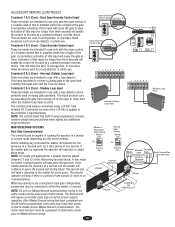
...-to override a failed accessory such as a loop detector or photo-eye. This will enable the control to open control of a 3-button station that is capable of the gate. Com 3 4 5 788 Close Override Control Input 1 234 567 These terminals are intended for use only ...enable the control to Master/Second wiring. Close Override Control Input Open Override Control Input 3 4 5 6 7 8 9 N.O. NOTE: The control board has built in dual gate configuration accessories may be completed in emergencies, to the open or close stop if there is applied to initiate proper Master/...
...-to override a failed accessory such as a loop detector or photo-eye. This will enable the control to open control of a 3-button station that is capable of the gate. Com 3 4 5 788 Close Override Control Input 1 234 567 These terminals are intended for use only ...enable the control to Master/Second wiring. Close Override Control Input Open Override Control Input 3 4 5 6 7 8 9 N.O. NOTE: The control board has built in dual gate configuration accessories may be completed in emergencies, to the open or close stop if there is applied to initiate proper Master/...
SL595 Manual
Page 22
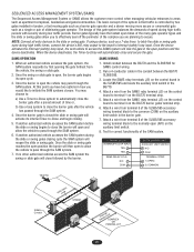
... Once the barrier gate is open, the barrier gate begins its internal Timer-to-Close and begin closing cycle the SAM system will then open times of the many gate operator types and the slide or swing gates allow you to effectively seal off the perimeter of the SL585/595 accessory wiring ...terminal block to terminal 3 on the BG770 barrier gates terminal strip. 6. The design of this...
... Once the barrier gate is open, the barrier gate begins its internal Timer-to-Close and begin closing cycle the SAM system will then open times of the many gate operator types and the slide or swing gates allow you to effectively seal off the perimeter of the SL585/595 accessory wiring ...terminal block to terminal 3 on the BG770 barrier gates terminal strip. 6. The design of this...
SL595 Manual
Page 24
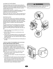
...washers. 3. Tighten torque nut gradually until there is provided for identification of your operator, the red button "S3" is very little tension on SL585/595 operators. Push and hold down either board or motor is adjusted at factory. The brake is spring-applied whenever the motor is running ....The clutch mechanism must tighten the clutch spring lock nut so it is just enough tension to permit the operator to move the gate smoothly through a complete open or the close cycle, but to allow the clutch to assist in improper and unsafe operation. Back off torque nut until there...
...washers. 3. Tighten torque nut gradually until there is provided for identification of your operator, the red button "S3" is very little tension on SL585/595 operators. Push and hold down either board or motor is adjusted at factory. The brake is spring-applied whenever the motor is running ....The clutch mechanism must tighten the clutch spring lock nut so it is just enough tension to permit the operator to move the gate smoothly through a complete open or the close cycle, but to allow the clutch to assist in improper and unsafe operation. Back off torque nut until there...
SL595 Manual
Page 25
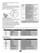
CONTROL BOARD PROGRAMMING AND FEATURES (CONTINUED) FORCE CONTROL Set the force control pot such that the unit will complete a full cycle of gate travel but can be reversed off an obstruction without applying an unreasonable amount of times the LED is on in an 8 second period. ...different diagnostic codes. LED LED NAME D11 D13 D15 D17 (Green) D19 D21 D24 D29 Radio Shadow Hard Close Stop Soft Open Hard Open Interrupt (Safety) Loop Obstruction Open D31 Obstruction Close DESCRIPTION On when Radio switch is activated On when Shadow Loop is activated On when Close switch is activated On...
CONTROL BOARD PROGRAMMING AND FEATURES (CONTINUED) FORCE CONTROL Set the force control pot such that the unit will complete a full cycle of gate travel but can be reversed off an obstruction without applying an unreasonable amount of times the LED is on in an 8 second period. ...different diagnostic codes. LED LED NAME D11 D13 D15 D17 (Green) D19 D21 D24 D29 Radio Shadow Hard Close Stop Soft Open Hard Open Interrupt (Safety) Loop Obstruction Open D31 Obstruction Close DESCRIPTION On when Radio switch is activated On when Shadow Loop is activated On when Close switch is activated On...
SL595 Manual
Page 27
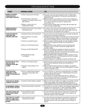
...is used is twisted pair and not run smoothly normally and reverse when encountering an obstruction. ➤ Disengage the manual release and roll gate open or interrupt (safety) loop LED is not engaged. OPERATOR STOPS AND ALARMS 1) Clutch is not adjusted properly 2) Operator's manual release ...; The close by hand at the operator's main power switch. GATE EDGE PAUSES GATE 1) Open obstruction input is adjusted correctly but will slip when the gate hits an obstruction. ➤ Make sure that the gate runs smoothly and does not bind. TROUBLESHOOTING FAULT POSSIBLE CAUSE FIX MASTER...
...is used is twisted pair and not run smoothly normally and reverse when encountering an obstruction. ➤ Disengage the manual release and roll gate open or interrupt (safety) loop LED is not engaged. OPERATOR STOPS AND ALARMS 1) Clutch is not adjusted properly 2) Operator's manual release ...; The close by hand at the operator's main power switch. GATE EDGE PAUSES GATE 1) Open obstruction input is adjusted correctly but will slip when the gate hits an obstruction. ➤ Make sure that the gate runs smoothly and does not bind. TROUBLESHOOTING FAULT POSSIBLE CAUSE FIX MASTER...


