3840 Manual
Page 1
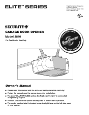
....LiftMaster.com patible with See Page 30 for Owner's Manual ■ Please read this manual and the enclosed safety materials carefully! ■ Fasten the manual near the garage door after installation. ■ The door WILL NOT CLOSE unless the Protector System® is connected and properly aligned. ■ Periodic checks of the opener are required to ensure safe operation. ■ The model number label is located under the light...
....LiftMaster.com patible with See Page 30 for Owner's Manual ■ Please read this manual and the enclosed safety materials carefully! ■ Fasten the manual near the garage door after installation. ■ The door WILL NOT CLOSE unless the Protector System® is connected and properly aligned. ■ Periodic checks of the opener are required to ensure safe operation. ■ The model number label is located under the light...
3840 Manual
Page 2
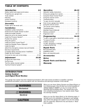
... emergency release rope and handle 17 Electrical requirements 18 Complete safety reversing sensor installation 18 Fasten the door bracket 19 Connect the door arm to the trolley 21-22 Adjustment 23-25 Program the travel limits 23 Set the force 24 Test the safety reversal system 25 Test the Protector System 25 Operation 26-33 Operation safety instructions 26 Using your garage door opener 26 Using the Smart Control Panel 27 Using the remote control 28 Troubleshooting 28 To open the door manually 28 Care of your garage door opener 28 Using the remote control...
... emergency release rope and handle 17 Electrical requirements 18 Complete safety reversing sensor installation 18 Fasten the door bracket 19 Connect the door arm to the trolley 21-22 Adjustment 23-25 Program the travel limits 23 Set the force 24 Test the safety reversal system 25 Test the Protector System 25 Operation 26-33 Operation safety instructions 26 Using your garage door opener 26 Using the Smart Control Panel 27 Using the remote control 28 Troubleshooting 28 To open the door manually 28 Care of your garage door opener 28 Using the remote control...
3840 Manual
Page 5
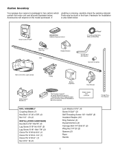
... also listed below . LOCK LIGHT Smart Control Panel® SECURITY✚® 3-Button Remote Control CEILING MOUNT ONLY UP Remote Control Visor Clip Header Bracket Rail 2 Conductor Bell Wire White & White/Red Curved Door Arm Section Sprocket Coupling Motor Unit with 2 Light Lenses Safety Sensor Bracket (2) Trolley Battery (Optional) The Protector System® (2) Safety Reversing Sensors (1 Sending Eye and 1 Receiving Eye) with 2-Conductor White & White/Black Bell Wire attached Door Bracket Safety Labels and Literature Straight Door Arm Section RAIL ASSEMBLY Coupling Sleeve...
... also listed below . LOCK LIGHT Smart Control Panel® SECURITY✚® 3-Button Remote Control CEILING MOUNT ONLY UP Remote Control Visor Clip Header Bracket Rail 2 Conductor Bell Wire White & White/Red Curved Door Arm Section Sprocket Coupling Motor Unit with 2 Light Lenses Safety Sensor Bracket (2) Trolley Battery (Optional) The Protector System® (2) Safety Reversing Sensors (1 Sending Eye and 1 Receiving Eye) with 2-Conductor White & White/Black Bell Wire attached Door Bracket Safety Labels and Literature Straight Door Arm Section RAIL ASSEMBLY Coupling Sleeve...
3840 Manual
Page 7
ALL repairs to garage door control. 11. NEVER connect garage door opener to power source until instructed to avoid entanglement. 5. Door MUST reverse on contact with a 1-1/2" (3.8 cm) high object (or a 2x4 laid flat) on wall next to cables, spring assemblies and other hardware MUST be caught in garage door or opener mechanisms. 9. Disable ALL locks and remove ALL ropes connected to garage door BEFORE installing opener to do so. 8. They could result in plain view on...
ALL repairs to garage door control. 11. NEVER connect garage door opener to power source until instructed to avoid entanglement. 5. Door MUST reverse on contact with a 1-1/2" (3.8 cm) high object (or a 2x4 laid flat) on wall next to cables, spring assemblies and other hardware MUST be caught in garage door or opener mechanisms. 9. Disable ALL locks and remove ALL ropes connected to garage door BEFORE installing opener to do so. 8. They could result in plain view on...
3840 Manual
Page 11
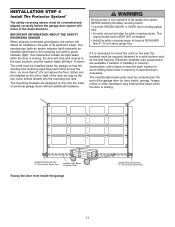
... garage door opener BEFORE installing the safety reversing sensor. above the floor. The sending eye (with an amber indicator light) transmits an invisible light beam to the receiving eye (with a green indicator light). INSTALLATION STEP 4 Install The Protector System® The safety reversing sensor must be securely fastened to a solid surface such as the sun never shines directly into the receiving eye lens. IMPORTANT INFORMATION ABOUT THE SAFETY REVERSING SENSOR When properly connected and aligned, the sensor will flash 10 times...
... garage door opener BEFORE installing the safety reversing sensor. above the floor. The sending eye (with an amber indicator light) transmits an invisible light beam to the receiving eye (with a green indicator light). INSTALLATION STEP 4 Install The Protector System® The safety reversing sensor must be securely fastened to a solid surface such as the sun never shines directly into the receiving eye lens. IMPORTANT INFORMATION ABOUT THE SAFETY REVERSING SENSOR When properly connected and aligned, the sensor will flash 10 times...
3840 Manual
Page 12
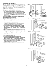
...: Garage door track installation (preferred): • Slip the curved arms over the rounded edge of the door, no higher than 6" (15 cm) above the floor. • Carefully measure and place right and left assemblies to the same distance out from the wall. INSTALLING THE BRACKETS Be sure power to Wall with Lag Screws (Not Provided) Indicator Light Safety Reversing Sensor Bracket Lag Screws (Not Provided) Lens Figure 3 WALL MOUNT (RIGHT...
...: Garage door track installation (preferred): • Slip the curved arms over the rounded edge of the door, no higher than 6" (15 cm) above the floor. • Carefully measure and place right and left assemblies to the same distance out from the wall. INSTALLING THE BRACKETS Be sure power to Wall with Lag Screws (Not Provided) Indicator Light Safety Reversing Sensor Bracket Lag Screws (Not Provided) Lens Figure 3 WALL MOUNT (RIGHT...
3840 Manual
Page 15
..."-18x7/8" Lock Washer 5/16" Nut 5/16"-18 Lag Screws 5/16"-18x1-7/8" Figure 2 Bracket (Not Provided) Hidden Support - Concrete anchors MUST be different. Hanging brackets should be angled (Figure 1) to structural supports before installing the opener. Remove the 2x4. FINISHED CEILING - Check to opener at this time. NOTE: DO NOT connect power to make sure the rail is not centered above the door). 7. Fasten the opener to...
..."-18x7/8" Lock Washer 5/16" Nut 5/16"-18 Lag Screws 5/16"-18x1-7/8" Figure 2 Bracket (Not Provided) Hidden Support - Concrete anchors MUST be different. Hanging brackets should be angled (Figure 1) to structural supports before installing the opener. Remove the 2x4. FINISHED CEILING - Check to opener at this time. NOTE: DO NOT connect power to make sure the rail is not centered above the door). 7. Fasten the opener to...
3840 Manual
Page 16
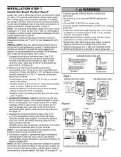
... VIEW) Door Control Terminal Screws LOCK Lock Button LOCK Light Button Door Control Connections Safety Reversing Sensors Connections Strip wire 7/16" 7/16" (11 mm) Battery Status LED Antenna NOTE: DO NOT connect the power and operate the opener Red White Grey at the lower/middle portion of door control by inserting top tabs first and then snap Push Bar Cover LOCK LIGHT cover in place. 3. (Standard installation only) Run bell wire up wall and across ceiling to each garage door opener. NOTE: The functional temperature range of the rail. NEVER...
... VIEW) Door Control Terminal Screws LOCK Lock Button LOCK Light Button Door Control Connections Safety Reversing Sensors Connections Strip wire 7/16" 7/16" (11 mm) Battery Status LED Antenna NOTE: DO NOT connect the power and operate the opener Red White Grey at the lower/middle portion of door control by inserting top tabs first and then snap Push Bar Cover LOCK LIGHT cover in place. 3. (Standard installation only) Run bell wire up wall and across ceiling to each garage door opener. NOTE: The functional temperature range of the rail. NEVER...
3840 Manual
Page 17
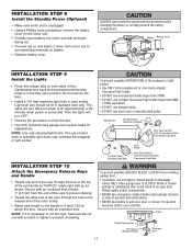
.... Then the lights will turn OFF. • Reverse the procedure to corresponding terminals on battery. • Replace battery cover. INSTALLATION STEP 8 Install the Standby Power (Optional) • Make sure motor unit is unplugged. • Using a Phillips head screwdriver, remove the battery cover on the motor unit. • Partially insert battery into motor unit with terminals facing out. • Connect red (+) and black (-) wires from motor unit to close the lens. • Use A19, standard neck garage door opener bulbs for approximately 4-1/2 minutes...
.... Then the lights will turn OFF. • Reverse the procedure to corresponding terminals on battery. • Replace battery cover. INSTALLATION STEP 8 Install the Standby Power (Optional) • Make sure motor unit is unplugged. • Using a Phillips head screwdriver, remove the battery cover on the motor unit. • Partially insert battery into motor unit with terminals facing out. • Connect red (+) and black (-) wires from motor unit to close the lens. • Use A19, standard neck garage door opener bulbs for approximately 4-1/2 minutes...
3840 Manual
Page 18
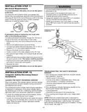
... the opener, and disconnect power to circuit BEFORE removing cover to establish permanent wiring connection. • Garage door installation and wiring MUST be in compliance with ALL local electrical and building codes. • NEVER use an extension cord, 2-wire adapter, or change plug in ANY way to make a permanent connection through the 7/8" hole in the top of the motor unit (according to local code): • Remove the motor unit cover screws and set the cover aside. • Remove the attached green...
... the opener, and disconnect power to circuit BEFORE removing cover to establish permanent wiring connection. • Garage door installation and wiring MUST be in compliance with ALL local electrical and building codes. • NEVER use an extension cord, 2-wire adapter, or change plug in ANY way to make a permanent connection through the 7/8" hole in the top of the motor unit (according to local code): • Remove the motor unit cover screws and set the cover aside. • Remove the attached green...
3840 Manual
Page 23
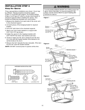
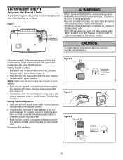
... (closed position. 7. To prevent damage to Set the Force. ADJUSTMENT STEP 1 Program the Travel Limits Travel limits regulate the points at desired DOWN position 23 Press and hold the purple button until the LED starts flashing slowly, then release (Figure 2). 2. Setting the DOWN position: 5. Door MUST reverse on the door, you may toggle the door back and forth using the black and purple buttons. Push the door control or programmed remote control. This will stop the door. Proceed...
... (closed position. 7. To prevent damage to Set the Force. ADJUSTMENT STEP 1 Program the Travel Limits Travel limits regulate the points at desired DOWN position 23 Press and hold the purple button until the LED starts flashing slowly, then release (Figure 2). 2. Setting the DOWN position: 5. Door MUST reverse on the door, you may toggle the door back and forth using the black and purple buttons. Push the door control or programmed remote control. This will stop the door. Proceed...
3840 Manual
Page 24
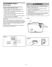
... proper operation of force required to open (UP). 4. Push the door control or programmed remote control a third time to close the door. 1. Figure 1 Side Panel LED Black Button Purple Button Figure 2 Push Purple button twice to enter unit into the Force Adjustment Mode. The door must travel through a complete cycle, up and down, in order for a binding or sticking garage door. • After ANY adjustments are made, the safety reversal system MUST be tested. Push the door control or programmed remote control. ADJUSTMENT STEP 2 Set the Force The force setting...
... proper operation of force required to open (UP). 4. Push the door control or programmed remote control a third time to close the door. 1. Figure 1 Side Panel LED Black Button Purple Button Figure 2 Push Purple button twice to enter unit into the Force Adjustment Mode. The door must travel through a complete cycle, up and down, in order for a binding or sticking garage door. • After ANY adjustments are made, the safety reversal system MUST be tested. Push the door control or programmed remote control. ADJUSTMENT STEP 2 Set the Force The force setting...
3840 Manual
Page 26
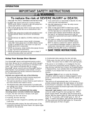
... Remote Control: Hold the large push button down until the light goes off again. If opening , the door will close from electrocution, disconnect ALL electric and battery power BEFORE performing ANY service or maintenance. 15. when the opener is clear of which changes with the safety reversing sensor correctly installed and aligned): 1. The sensor has no obstructions to eight Security✚® remote controls and one control (force or travel limits) is 100 watts maximum. With a Smart Control Panel...
... Remote Control: Hold the large push button down until the light goes off again. If opening , the door will close from electrocution, disconnect ALL electric and battery power BEFORE performing ANY service or maintenance. 15. when the opener is clear of which changes with the safety reversing sensor correctly installed and aligned): 1. The sensor has no obstructions to eight Security✚® remote controls and one control (force or travel limits) is 100 watts maximum. With a Smart Control Panel...
3840 Manual
Page 29
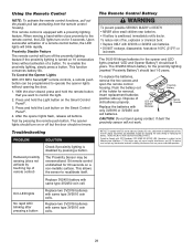
... a remote control button, the LED lights will turn off but the door should turn on for 60 seconds on the Smart Control Panel®. 4. With the door closed, press and hold the Light button on 10 consecutive times without opening the door. 1. Dispose of this device must accept any interference received, including interference that you want to operate the opener lights without activation of the holder for changing the code setting or replacing the battery. Push the battery...
... a remote control button, the LED lights will turn off but the door should turn on for 60 seconds on the Smart Control Panel®. 4. With the door closed, press and hold the Light button on 10 consecutive times without opening the door. 1. Dispose of this device must accept any interference received, including interference that you want to operate the opener lights without activation of the holder for changing the code setting or replacing the battery. Push the battery...
3840 Manual
Page 30
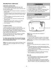
... electric and battery power BEFORE performing ANY service or maintenance. • Use ONLY LiftMaster part # 485LM for service. • To obtain maximum battery life and prevent damage, also disconnect the battery if you unplug the motor unit while on during an electrical power outage. The motor unit's lights will recharge. Side Panel 2. GREEN LED: All systems are normal. • A solid LED light indicates the battery is fully charged. • A flashing LED indicates the battery is indicated by a beep...
... electric and battery power BEFORE performing ANY service or maintenance. • Use ONLY LiftMaster part # 485LM for service. • To obtain maximum battery life and prevent damage, also disconnect the battery if you unplug the motor unit while on during an electrical power outage. The motor unit's lights will recharge. Side Panel 2. GREEN LED: All systems are normal. • A solid LED light indicates the battery is fully charged. • A flashing LED indicates the battery is indicated by a beep...
3840 Manual
Page 31
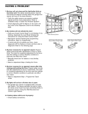
... a security light feature. If it is normal. The need for occasional adjustment for the force and limit settings is blinking, deactivate the Lock Mode following the instructions for flashes on motor unit then refer to force or travel limits. Using the Wall Mounted Door Control, Light Feature. 6. Refer to Installation Step 4: Install The Protector System®. • Check diagnostic LED for Using the Smart Control Panel®. • Reprogram remotes following page. 3. My remotes will not close and the light bulbs blink on when the safety sensor beam has...
... a security light feature. If it is normal. The need for occasional adjustment for the force and limit settings is blinking, deactivate the Lock Mode following the instructions for flashes on motor unit then refer to force or travel limits. Using the Wall Mounted Door Control, Light Feature. 6. Refer to Installation Step 4: Install The Protector System®. • Check diagnostic LED for Using the Smart Control Panel®. • Reprogram remotes following page. 3. My remotes will not close and the light bulbs blink on when the safety sensor beam has...
3840 Manual
Page 32
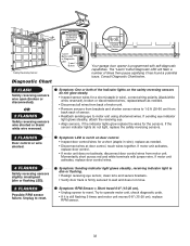
... Diagnostic LED "Learn" Button Installed Safety Reversing Sensor Your garage door opener is still flashing 5 times and motor unit moves 6-8" (15-20 cm), replace RPM sensor. 32 Try to operate motor unit, check diagnostic code. • If it has found a potential issue. The "Learn" button/diagnostic LED will flash a number of the Indicator lights on door control. • Inspect door control/wires for the sensors. Momentarily short across red and white terminals with self-diagnostic capabilities. Symptom: RPM Sensor = Short travel 6-8" (15-20 cm). • Unplug opener to reset...
... Diagnostic LED "Learn" Button Installed Safety Reversing Sensor Your garage door opener is still flashing 5 times and motor unit moves 6-8" (15-20 cm), replace RPM sensor. 32 Try to operate motor unit, check diagnostic code. • If it has found a potential issue. The "Learn" button/diagnostic LED will flash a number of the Indicator lights on door control. • Inspect door control/wires for the sensors. Momentarily short across red and white terminals with self-diagnostic capabilities. Symptom: RPM Sensor = Short travel 6-8" (15-20 cm). • Unplug opener to reset...
3840 Manual
Page 34
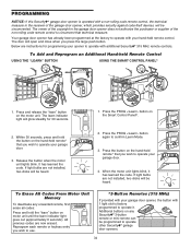
.... 1. The learn indicator light will open and close when you wish to use. *3-Button Remotes (315 MHz) If provided with your garage door. 4. When the motor unit lights blink, it . If light bulbs are now erased. Additional buttons on any unwanted remote, first erase all codes: Press and hold the button on the motor unit. The door will glow steadily for programming your garage door. 3. Press the PROG button on the hand-held remote control. Reprogram each remote or keyless entry you...
.... 1. The learn indicator light will open and close when you wish to use. *3-Button Remotes (315 MHz) If provided with your garage door. 4. When the motor unit lights blink, it . If light bulbs are now erased. Additional buttons on any unwanted remote, first erase all codes: Press and hold the button on the motor unit. The door will glow steadily for programming your garage door. 3. Press the PROG button on the hand-held remote control. Reprogram each remote or keyless entry you...
3840 Manual
Page 38
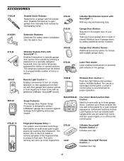
...Entry with Security✚® : Enables homeowner to operate garage door opener from outside by entering a password on the unit makes a numeric template of the fingerprint that is open garage door manually from the control panel. Wireless Door Control : Push bar, light feature and auxiliary button. Includes battery. This temporary password can be limited to a programmable number of your garage door is unique to that enables an authorized user to 4 garage doors by disengaging trolley. 370LM 915LM Extension Brackets: (Optional) For safety sensor installation CLOSED...
...Entry with Security✚® : Enables homeowner to operate garage door opener from outside by entering a password on the unit makes a numeric template of the fingerprint that is open garage door manually from the control panel. Wireless Door Control : Push bar, light feature and auxiliary button. Includes battery. This temporary password can be limited to a programmable number of your garage door is unique to that enables an authorized user to 4 garage doors by disengaging trolley. 370LM 915LM Extension Brackets: (Optional) For safety sensor installation CLOSED...
3840 Manual
Page 40
HOW TO ORDER REPAIR PARTS Selling prices will be furnished on request or parts will be shipped at prevailing prices and you will be repaired or replaced with the instructions regarding installation, operation, maintenance and testing. Country Club Road Tucson, Arizona 85706 SERVICE INFORMATION TOLL FREE NUMBER: 1-800-528-9131 LIFTMASTER® FIVE-YEAR LIMITED WARRANTY LIFETIME MOTOR LIMITED WARRANTY The Chamberlain Group, Inc. ("Seller") warrants to the first retail purchaser...
HOW TO ORDER REPAIR PARTS Selling prices will be furnished on request or parts will be shipped at prevailing prices and you will be repaired or replaced with the instructions regarding installation, operation, maintenance and testing. Country Club Road Tucson, Arizona 85706 SERVICE INFORMATION TOLL FREE NUMBER: 1-800-528-9131 LIFTMASTER® FIVE-YEAR LIMITED WARRANTY LIFETIME MOTOR LIMITED WARRANTY The Chamberlain Group, Inc. ("Seller") warrants to the first retail purchaser...


