
3840 Manual
Page 1
® GARAGE DOOR OPENER Model 3840 For Residential Use Only Com Details The Chamberlain Group, Inc. 845 Larch Avenue Elmhurst, Illinois 60126-1196 www.LiftMaster.com patible with See Page 30 for Owner's Manual ■ Please read this manual and the enclosed safety materials carefully! ■ Fasten the... installation. ■ The door WILL NOT CLOSE unless the Protector System® is connected and properly aligned. ■ Periodic checks of the opener are required to ensure safe operation. ■ The model number label is located under the light lens on the left side panel of your...
® GARAGE DOOR OPENER Model 3840 For Residential Use Only Com Details The Chamberlain Group, Inc. 845 Larch Avenue Elmhurst, Illinois 60126-1196 www.LiftMaster.com patible with See Page 30 for Owner's Manual ■ Please read this manual and the enclosed safety materials carefully! ■ Fasten the... installation. ■ The door WILL NOT CLOSE unless the Protector System® is connected and properly aligned. ■ Periodic checks of the opener are required to ensure safe operation. ■ The model number label is located under the light lens on the left side panel of your...
3840 Manual
Page 2
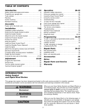
... 8 Install the header bracket 9 Attach the rail to the header bracket 10 Install the Protector System 11-13 Position the opener 14 Hang the opener 15 Install the Smart Control Panel 16 Install the Standby Power (Optional 17 Install the lights 17 Attach the emergency release rope... parts 37 Accessories 38 Notes 39 Repair Parts and Service 40 Warranty 40 INTRODUCTION Safety Symbol and Signal Word Review This garage door opener has been designed and tested to offer safe service provided it is installed, operated, maintained and tested in strict accordance with the ...
... 8 Install the header bracket 9 Attach the rail to the header bracket 10 Install the Protector System 11-13 Position the opener 14 Hang the opener 15 Install the Smart Control Panel 16 Install the Standby Power (Optional 17 Install the lights 17 Attach the emergency release rope... parts 37 Accessories 38 Notes 39 Repair Parts and Service 40 Warranty 40 INTRODUCTION Safety Symbol and Signal Word Review This garage door opener has been designed and tested to offer safe service provided it is installed, operated, maintained and tested in strict accordance with the ...

3840 Manual
Page 3
...required. • NEVER try to loosen, move or adjust garage door, door springs, cables, pulleys, brackets or their hardware, ALL of the opener, instructions will call a trained door systems technician if garage door binds, sticks, or is not sticking or binding: 1. Carpenter's Level (Optional...which are under EXTREME tension. • Disable ALL locks and remove ALL ropes connected to garage door BEFORE installing and operating garage door opener to avoid malfunction and damage. If balanced, it should stay in place, supported entirely by its springs. 2. To prevent possible SERIOUS...
...required. • NEVER try to loosen, move or adjust garage door, door springs, cables, pulleys, brackets or their hardware, ALL of the opener, instructions will call a trained door systems technician if garage door binds, sticks, or is not sticking or binding: 1. Carpenter's Level (Optional...which are under EXTREME tension. • Disable ALL locks and remove ALL ropes connected to garage door BEFORE installing and operating garage door opener to avoid malfunction and damage. If balanced, it should stay in place, supported entirely by its springs. 2. To prevent possible SERIOUS...
3840 Manual
Page 4
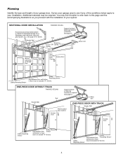
Planning Identify the type and height of your opener. Additional materials may find it helpful to refer back to this page and the accompanying illustrations as you proceed with glass panels, etc.). You may ...
Planning Identify the type and height of your opener. Additional materials may find it helpful to refer back to this page and the accompanying illustrations as you proceed with glass panels, etc.). You may ...
3840 Manual
Page 5
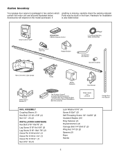
... below . Hardware for installation Accessories will depend on the model purchased. contain the motor unit and all parts illustrated below . Carton Inventory Your garage door opener is packaged in the foam. LOCK LIGHT Smart Control Panel® SECURITY✚® 3-Button Remote Control CEILING MOUNT ONLY UP Remote Control Visor Clip...
... below . Hardware for installation Accessories will depend on the model purchased. contain the motor unit and all parts illustrated below . Carton Inventory Your garage door opener is packaged in the foam. LOCK LIGHT Smart Control Panel® SECURITY✚® 3-Button Remote Control CEILING MOUNT ONLY UP Remote Control Visor Clip...

3840 Manual
Page 6
... pointed away from the motor unit. ASSEMBLY STEP 1 Fasten the Rail to the Motor Unit To avoid installation difficulties, do not run the garage door opener until the coupling fits securely over the rail sprocket. • Slide the rail through the motor unit bracket until instructed to do so.
... pointed away from the motor unit. ASSEMBLY STEP 1 Fasten the Rail to the Motor Unit To avoid installation difficulties, do not run the garage door opener until the coupling fits securely over the rail sprocket. • Slide the rail through the motor unit bracket until instructed to do so.
3840 Manual
Page 7
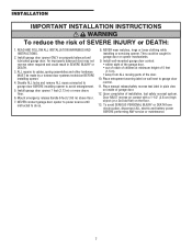
...wall next to cables, spring assemblies and other hardware MUST be caught in SEVERE INJURY or DEATH. 3. They could result in garage door or opener mechanisms. 9. Door MUST reverse on contact with a 1-1/2" (3.8 cm) high object (or a 2x4 laid flat) on properly balanced and lubricated...of the door. 10. READ AND FOLLOW ALL INSTALLATION WARNINGS AND INSTRUCTIONS. 2. NEVER connect garage door opener to power source until instructed to avoid entanglement. 5. Install garage door opener ONLY on the floor. 13. An improperly balanced door may not reverse when required and could be ...
...wall next to cables, spring assemblies and other hardware MUST be caught in SEVERE INJURY or DEATH. 3. They could result in garage door or opener mechanisms. 9. Door MUST reverse on contact with a 1-1/2" (3.8 cm) high object (or a 2x4 laid flat) on properly balanced and lubricated...of the door. 10. READ AND FOLLOW ALL INSTALLATION WARNINGS AND INSTRUCTIONS. 2. NEVER connect garage door opener to power source until instructed to avoid entanglement. 5. Install garage door opener ONLY on the floor. 13. An improperly balanced door may not reverse when required and could be ...
3840 Manual
Page 8
... a 2x4 (on wall or ceiling), use the maximum height possible, or refer to the highest point of inches exceeds the height available in the way; Open your garage, use lag screws (not provided) to securely fasten the 2x4 to your door. 1. NOTE: If the total number of travel clearance for sectional...
... a 2x4 (on wall or ceiling), use the maximum height possible, or refer to the highest point of inches exceeds the height available in the way; Open your garage, use lag screws (not provided) to securely fasten the 2x4 to your door. 1. NOTE: If the total number of travel clearance for sectional...

3840 Manual
Page 10
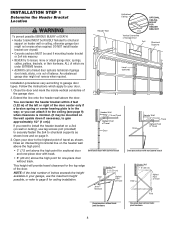
...help. Header Wall Header Bracket Rail Bracket INSTALLATION STEP 3 Attach the Rail to secure. Use packing material as illustrated. • Position the opener on each side of the rail, as a protective base. Garage Door Rail Ring Fastener Header Bracket Clevis Pin 5/16"x2-3/4" Spacers Rail Bracket ...Rail Opener Carton or Temporary Support HARDWARE SHOWN ACTUAL SIZE Clevis Pin 5/16"x2-3/4" 10 Ring Fastener Spacer Place the spacers inside the bracket on...
...help. Header Wall Header Bracket Rail Bracket INSTALLATION STEP 3 Attach the Rail to secure. Use packing material as illustrated. • Position the opener on each side of the rail, as a protective base. Garage Door Rail Ring Fastener Header Bracket Clevis Pin 5/16"x2-3/4" Spacers Rail Bracket ...Rail Opener Carton or Temporary Support HARDWARE SHOWN ACTUAL SIZE Clevis Pin 5/16"x2-3/4" 10 Ring Fastener Spacer Place the spacers inside the bracket on...
3840 Manual
Page 11
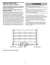
...eye lens. If installing in the down direction. The invisible light beam path must be connected and aligned correctly before the garage door opener will detect an obstacle in masonry if repositioning is NO HIGHER than 6" (15 cm) above floor Invisible Light Beam Protection Area ...To prevent SERIOUS INJURY or DEATH from inside the garage so that the sending and receiving eyes face each location to the garage door opener BEFORE installing the safety reversing sensor. The mounting brackets are available if needed. The sending eye (with an amber indicator light) transmits...
...eye lens. If installing in the down direction. The invisible light beam path must be connected and aligned correctly before the garage door opener will detect an obstacle in masonry if repositioning is NO HIGHER than 6" (15 cm) above floor Invisible Light Beam Protection Area ...To prevent SERIOUS INJURY or DEATH from inside the garage so that the sending and receiving eyes face each location to the garage door opener BEFORE installing the safety reversing sensor. The mounting brackets are available if needed. The sending eye (with an amber indicator light) transmits...
3840 Manual
Page 12
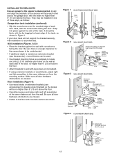
... MOUNT (RIGHT SIDE) Door Track Lip Indicator Light Safety Reversing Sensor Bracket Lens Figure 2 WALL MOUNT (RIGHT SIDE) IGWnasairldal ege Fasten Wood Block to the opener is enough clearance for the sensor beam to locate and drill (2) 3/16" diameter pilot holes on the wall at the same distance out from the...
... MOUNT (RIGHT SIDE) Door Track Lip Indicator Light Safety Reversing Sensor Bracket Lens Figure 2 WALL MOUNT (RIGHT SIDE) IGWnasairldal ege Fasten Wood Block to the opener is enough clearance for the sensor beam to locate and drill (2) 3/16" diameter pilot holes on the wall at the same distance out from the...
3840 Manual
Page 14
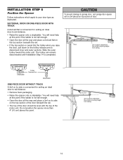
...Door 2x4 is used to determine the correct mounting height from ceiling. 14 Top of Door 2x4 is used to garage door, rest garage door opener rail on 2x4 placed on the top section of the door beneath the rail. • The top of the door should be level with ...point if the ladder is convenient for setting an ideal door-to -rail distance. • Remove foam packaging. • Raise the opener onto a stepladder. INSTALLATION STEP 5 Position the Opener Follow instructions which apply to disconnect inner and outer sections. SECTIONAL DOOR OR ONE-PIECE DOOR WITH TRACK A 2x4 laid flat is...
...Door 2x4 is used to determine the correct mounting height from ceiling. 14 Top of Door 2x4 is used to garage door, rest garage door opener rail on 2x4 placed on the top section of the door beneath the rail. • The top of the door should be level with ...point if the ladder is convenient for setting an ideal door-to -rail distance. • Remove foam packaging. • Raise the opener onto a stepladder. INSTALLATION STEP 5 Position the Opener Follow instructions which apply to disconnect inner and outer sections. SECTIONAL DOOR OR ONE-PIECE DOOR WITH TRACK A 2x4 laid flat is...
3840 Manual
Page 15
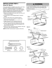
... line with 5/16"-18x7/8" hex bolts, lock washers and nuts. 6. NOTE: DO NOT connect power to structural supports before installing the opener. Remove the 2x4. FINISHED CEILING - Hanging brackets should be different. Check to the structural support. 2. Concrete anchors MUST be used if... installing ANY brackets into masonry. INSTALLATION STEP 6 Hang the Opener Three representative installations are not provided. 1. Cut both pieces of the motor unit to make sure the rail is not centered above the ...
... line with 5/16"-18x7/8" hex bolts, lock washers and nuts. 6. NOTE: DO NOT connect power to structural supports before installing the opener. Remove the 2x4. FINISHED CEILING - Hanging brackets should be different. Check to the structural support. 2. Concrete anchors MUST be used if... installing ANY brackets into masonry. INSTALLATION STEP 6 Hang the Opener Three representative installations are not provided. 1. Cut both pieces of the motor unit to make sure the rail is not centered above the ...
3840 Manual
Page 16
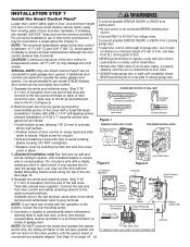
...there are desired to secure wire in tab with the Safety Reversing Sensor wires along the top of the buttons, loosen the top mounting screw. 5. opener, it may damage the LCD screen. Twist like colored wires together. R W 1 2 (BACK VIEW) Door Control Terminal Screws LOCK Lock Button LOCK... Safety Reversing Sensors Connections Strip wire 7/16" 7/16" (11 mm) Battery Status LED Antenna NOTE: DO NOT connect the power and operate the opener Red White Grey at a minimum height of 5 feet (1.5 m) where small children cannot reach, away from the end of door control by inserting ...
...there are desired to secure wire in tab with the Safety Reversing Sensor wires along the top of the buttons, loosen the top mounting screw. 5. opener, it may damage the LCD screen. Twist like colored wires together. R W 1 2 (BACK VIEW) Door Control Terminal Screws LOCK Lock Button LOCK... Safety Reversing Sensors Connections Strip wire 7/16" 7/16" (11 mm) Battery Status LED Antenna NOTE: DO NOT connect the power and operate the opener Red White Grey at a minimum height of 5 feet (1.5 m) where small children cannot reach, away from the end of door control by inserting ...
3840 Manual
Page 17
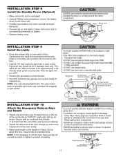
... overhand knot at least 1" (2.5 cm) from the end of the rope to close the lens. • Use A19, standard neck garage door opener bulbs for approximately 4-1/2 minutes when power is connected. Trolley Trolley Release Arm Emergency Release Handle NOTICE Overhand Knot 17 Then the lights will turn OFF...the endpanel or light socket. Light bulb size should be A19, standard neck only. If rope knot becomes untied, you could result in the fully open or closed. Release Tab 100 Watt (Max) Standard Light Bulb or Mini-Twist 26 Watt (100 W equivalent) (Max) Fluorescent Light Bulb or ...
... overhand knot at least 1" (2.5 cm) from the end of the rope to close the lens. • Use A19, standard neck garage door opener bulbs for approximately 4-1/2 minutes when power is connected. Trolley Trolley Release Arm Emergency Release Handle NOTICE Overhand Knot 17 Then the lights will turn OFF...the endpanel or light socket. Light bulb size should be A19, standard neck only. If rope knot becomes untied, you could result in the fully open or closed. Release Tab 100 Watt (Max) Standard Light Bulb or Mini-Twist 26 Watt (100 W equivalent) (Max) Fluorescent Light Bulb or ...
3840 Manual
Page 18
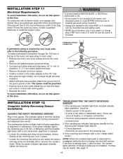
...times (if bulbs are correct. INSTALLATION STEP 11 Electrical Requirements To avoid installation difficulties, do not run the opener at opener connections. • Incorrect wiring between sensors and opener. • A broken wire. 2. Black Wire Wire Nuts Ground Tab Ground Wire Green Ground Screw White ... is off, dim, or flickering (and the invisible light beam path is not obstructed), alignment is required by your garage door opener has a grounding type plug with moving parts. • Reinstall the cover. TROUBLESHOOTING THE SAFETY REVERSING SENSORS 1. If the receiving eye...
...times (if bulbs are correct. INSTALLATION STEP 11 Electrical Requirements To avoid installation difficulties, do not run the opener at opener connections. • Incorrect wiring between sensors and opener. • A broken wire. 2. Black Wire Wire Nuts Ground Tab Ground Wire Green Ground Screw White ... is off, dim, or flickering (and the invisible light beam path is not obstructed), alignment is required by your garage door opener has a grounding type plug with moving parts. • Reinstall the cover. TROUBLESHOOTING THE SAFETY REVERSING SENSORS 1. If the receiving eye...
3840 Manual
Page 19
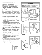
... the top edge of the bracket 2"-4" (5-10 cm) below the top edge of the door, OR directly below and on your door manufacturer for an opener installation door reinforcement kit. Secure the door bracket using the self-threading screws (Figure 3). HARDWARE SHOWN ACTUAL SIZE Self-Threading Screw 1/4"-14x5/8" Fiberglass, aluminum or...
... the top edge of the bracket 2"-4" (5-10 cm) below the top edge of the door, OR directly below and on your door manufacturer for an opener installation door reinforcement kit. Secure the door bracket using the self-threading screws (Figure 3). HARDWARE SHOWN ACTUAL SIZE Self-Threading Screw 1/4"-14x5/8" Fiberglass, aluminum or...
3840 Manual
Page 21
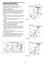
...; Fasten straight door arm section to outer trolley with bolts, lock washers and nuts. Trolley will re-engage automatically when opener is fully closed. Pull the emergency release handle toward the opener at a 45° angle so that line up and join with the 5/16"x1" clevis pin. Pull the emergency release...
...; Fasten straight door arm section to outer trolley with bolts, lock washers and nuts. Trolley will re-engage automatically when opener is fully closed. Pull the emergency release handle toward the opener at a 45° angle so that line up and join with the 5/16"x1" clevis pin. Pull the emergency release...
3840 Manual
Page 22
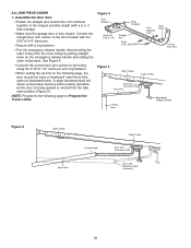
... clevis pin. • Secure with a ring fastener. • Pull the emergency release handle, disconnecting the outer trolley from the fully open as the door is fully closed from the inner trolley by pulling straight down on the following page to the longest possible length (with ... bucking and/or jerking operation as illustrated below. NOTE: Proceed to the following page, the door should not have a "backward" slant when fully open position (Figure 6). Figure 4 Door Bracket Ring Fastener Clevis Pin 5/16"x1-1/4" Straight Arm Bolts 5/16"-18x7/8 Lock Washers 5/16" Nuts 5/16...
... clevis pin. • Secure with a ring fastener. • Pull the emergency release handle, disconnecting the outer trolley from the fully open as the door is fully closed from the inner trolley by pulling straight down on the following page to the longest possible length (with ... bucking and/or jerking operation as illustrated below. NOTE: Proceed to the following page, the door should not have a "backward" slant when fully open position (Figure 6). Figure 4 Door Bracket Ring Fastener Clevis Pin 5/16"x1-1/4" Straight Arm Bolts 5/16"-18x7/8 Lock Washers 5/16" Nuts 5/16...
3840 Manual
Page 23
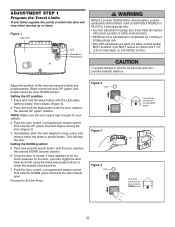
...on the door, you may toggle the door back and forth using the black and purple buttons. To prevent damage to vehicles, be sure fully open ) limit and begins closing garage door. • Incorrect adjustment of safety reversal system. • NEVER use force adjustments to close ) limit ... there appears to Set the Force. Press and hold until the LED starts flashing slowly, then release (Figure 2). 2. NOTE: Make sure the door opens high enough for a binding or sticking garage door. • After ANY adjustments are made, the safety reversal system MUST be too much pressure on ...
...on the door, you may toggle the door back and forth using the black and purple buttons. To prevent damage to vehicles, be sure fully open ) limit and begins closing garage door. • Incorrect adjustment of safety reversal system. • NEVER use force adjustments to close ) limit ... there appears to Set the Force. Press and hold until the LED starts flashing slowly, then release (Figure 2). 2. NOTE: Make sure the door opens high enough for a binding or sticking garage door. • After ANY adjustments are made, the safety reversal system MUST be too much pressure on ...


