Service Manual
Page 10
...). 3. Parts Catalog contains illustrations and part numbers for making scanner adjustments and removing and installing FRUs. 5. 4036-501 Preface This manual describes the Lexmark X7500 Scanner (4036-501) and contains maintenance procedures for service personnel only. General Information contains a general description of the scanner and the maintenance approach used to repair it. this chapter...
...). 3. Parts Catalog contains illustrations and part numbers for making scanner adjustments and removing and installing FRUs. 5. 4036-501 Preface This manual describes the Lexmark X7500 Scanner (4036-501) and contains maintenance procedures for service personnel only. General Information contains a general description of the scanner and the maintenance approach used to repair it. this chapter...

Service Manual
Page 12
4036-501 Acronyms ADF AGC AOC APS CCD CPU DADF DIMM E FTP GND HDD I/O JBIG JPEG KBS KL LDAP LVPS MFD MFP PDF PPM PWBA ROM S SE TIFF TTY UI VAC VDC Automatic Direction Finder Automatic Gain Control Abnormal Operating Condition Automatic Paper Size Charged Couple Device ... Per Minute Printed Wiring Board Assembly Read Only Memory Screw System Engineer Tagged Image File Format Teletypewriter User Interface Volts alternating current Volts direct current 1-2 Service Manual
4036-501 Acronyms ADF AGC AOC APS CCD CPU DADF DIMM E FTP GND HDD I/O JBIG JPEG KBS KL LDAP LVPS MFD MFP PDF PPM PWBA ROM S SE TIFF TTY UI VAC VDC Automatic Direction Finder Automatic Gain Control Abnormal Operating Condition Automatic Paper Size Charged Couple Device ... Per Minute Printed Wiring Board Assembly Read Only Memory Screw System Engineer Tagged Image File Format Teletypewriter User Interface Volts alternating current Volts direct current 1-2 Service Manual
Service Manual
Page 14
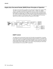
4036-501 Duplex Auto Document Feeder (DADF) Power Principles of the processing, the control card sends commands to the various DADF components. 1-4 Service Manual The voltage is then sent to the control card. The voltage travels from the scanner cable into the scanner system board where it to function. ...
4036-501 Duplex Auto Document Feeder (DADF) Power Principles of the processing, the control card sends commands to the various DADF components. 1-4 Service Manual The voltage is then sent to the control card. The voltage travels from the scanner cable into the scanner system board where it to function. ...
Service Manual
Page 16
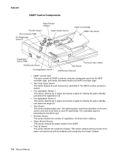
... Sensor The sensor detects paper size. This sensor utilizes a timing control of the paper conveyance as well as analyzes and recognizes the length of paper. 1-6 Service Manual 4036-501 DADF Control Components • DADF Control Card The card controls all DADF functions, executes commands sent from the MFD controller cage, and sends...
... Sensor The sensor detects paper size. This sensor utilizes a timing control of the paper conveyance as well as analyzes and recognizes the length of paper. 1-6 Service Manual 4036-501 DADF Control Components • DADF Control Card The card controls all DADF functions, executes commands sent from the MFD controller cage, and sends...
Service Manual
Page 18
... belt (6 mm). The registration roll drive motor provides the rotation power with the each gear of the gear (23T/48T), the rotation power is actuated. 1-8 Service Manual The DADF large roll drive assembly provides the rotation power with the center gear of the registration roll gear and the pick 2 roller assembly respectively...
... belt (6 mm). The registration roll drive motor provides the rotation power with the each gear of the gear (23T/48T), the rotation power is actuated. 1-8 Service Manual The DADF large roll drive assembly provides the rotation power with the center gear of the registration roll gear and the pick 2 roller assembly respectively...
Service Manual
Page 20
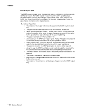
... moved to scan page 2 of the paper following page 1 using a combination of the exit/reverse roll discharges the paper onto the DADF output tray. 1-10 Service Manual 4036-501 DADF Paper Path The DADF moves the paper along the paper path using the gate change mechanism of the duplex function. 1. The DADF...
... moved to scan page 2 of the paper following page 1 using a combination of the exit/reverse roll discharges the paper onto the DADF output tray. 1-10 Service Manual 4036-501 DADF Paper Path The DADF moves the paper along the paper path using the gate change mechanism of the duplex function. 1. The DADF...
Service Manual
Page 22
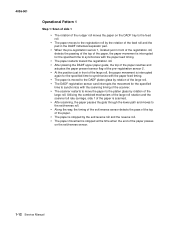
... exit/reverse roll and the reverse roll. • The paper movement is stopped by rotation of the paper passes on the exit/reverse sensor. 1-12 Service Manual 4036-501 Operational Pattern 1 Step 1: Scan of side 1 • The rotation of the nudger roll moves the paper on the DADF tray to the feed...
... exit/reverse roll and the reverse roll. • The paper movement is stopped by rotation of the paper passes on the exit/reverse sensor. 1-12 Service Manual 4036-501 Operational Pattern 1 Step 1: Scan of side 1 • The rotation of the nudger roll moves the paper on the DADF tray to the feed...
Service Manual
Page 24
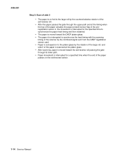
... at the timing when the top of the paper actuates the paper present sensor flag of the paper passes on the exit/reverse sensor. 1-14 Service Manual registration sensor 2, the movement is interrupted for the specified time to synchronize the paper feed timing and then restarted. • The paper is moved toward...
... at the timing when the top of the paper actuates the paper present sensor flag of the paper passes on the exit/reverse sensor. 1-14 Service Manual registration sensor 2, the movement is interrupted for the specified time to synchronize the paper feed timing and then restarted. • The paper is moved toward...
Service Manual
Page 26
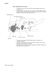
... pre- registration sensor #2. 4036-501 Step 3: High speed reverse rotation • The paper is then interrupted for a specific amount of the exit/reverse roll. 1-16 Service Manual
... pre- registration sensor #2. 4036-501 Step 3: High speed reverse rotation • The paper is then interrupted for a specific amount of the exit/reverse roll. 1-16 Service Manual

Service Manual
Page 28
... the passing the top of the paper, the paper movement is nipped by the rotation of the paper passes to the exit/reverse sensor. 1-18 Service Manual
... the passing the top of the paper, the paper movement is nipped by the rotation of the paper passes to the exit/reverse sensor. 1-18 Service Manual
Service Manual
Page 30
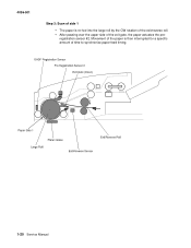
4036-501 Step 3: Scan of side 1 • The paper is then interrupted for a specific amount of the exit gate, the paper actuates the pre- Movement of the paper is re-fed into the large roll by the CW rotation of the exit/reverse roll. • After passing over the upper side of time to synchronize paper feed timing. 1-20 Service Manual registration sensor #2.
4036-501 Step 3: Scan of side 1 • The paper is then interrupted for a specific amount of the exit gate, the paper actuates the pre- Movement of the paper is re-fed into the large roll by the CW rotation of the exit/reverse roll. • After passing over the upper side of time to synchronize paper feed timing. 1-20 Service Manual registration sensor #2.
Service Manual
Page 32
... in the direction of the large roll to duplex. • Exit/Reverse Solenoid This solenoid separates the reverse roll from the upper exit roll. 1-22 Service Manual
... in the direction of the large roll to duplex. • Exit/Reverse Solenoid This solenoid separates the reverse roll from the upper exit roll. 1-22 Service Manual

Service Manual
Page 34
... status information to the various scanner components; The system card processes that is connected to function. Acting on /off the motor and exposure lamp. 1-24 Service Manual switching on the results of the processing, the system card sends commands to the system card. Sensors in ROM. Every electrical component within the scanner...
... status information to the various scanner components; The system card processes that is connected to function. Acting on /off the motor and exposure lamp. 1-24 Service Manual switching on the results of the processing, the system card sends commands to the system card. Sensors in ROM. Every electrical component within the scanner...
Service Manual
Page 36
... The lamp provides the electric power to light the exposure lamp. • Scanner Motor Card The card controls the rotation of the scanner motor. 1-26 Service Manual
... The lamp provides the electric power to light the exposure lamp. • Scanner Motor Card The card controls the rotation of the scanner motor. 1-26 Service Manual
Service Manual
Page 38
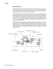
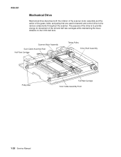
The purpose of the drive is to provide energy for movement of the gears, belts, and pulley that are used to transmit and control drive to the CCD card lens. 1-28 Service Manual 4036-501 Mechanical Drive Mechanical drive describes both the rotation of the scanner motor assembly and the action of the full and half rate carriages while maintaining the focus distance to the various components throughout the scanner.
The purpose of the drive is to provide energy for movement of the gears, belts, and pulley that are used to transmit and control drive to the CCD card lens. 1-28 Service Manual 4036-501 Mechanical Drive Mechanical drive describes both the rotation of the scanner motor assembly and the action of the full and half rate carriages while maintaining the focus distance to the various components throughout the scanner.

Service Manual
Page 40
Only the image projected through the left side DADF platen glass is obtained. 1-30 Service Manual The half rate carriage moves at half the rate of scan. DADF Mode Scans the document being fed through the DADF through the left side DADF platen glass. The half and full rate carriages are in a fixed position during this type of the full rate carriage to maintain the proper focal length from the document to the CCD card lens. 2. 4036-501 Scanning Methods 1. Platen Mode Scans the document placed on the platen glass by movement of the full rate carriage.
Only the image projected through the left side DADF platen glass is obtained. 1-30 Service Manual The half rate carriage moves at half the rate of scan. DADF Mode Scans the document being fed through the DADF through the left side DADF platen glass. The half and full rate carriages are in a fixed position during this type of the full rate carriage to maintain the proper focal length from the document to the CCD card lens. 2. 4036-501 Scanning Methods 1. Platen Mode Scans the document placed on the platen glass by movement of the full rate carriage.
Service Manual
Page 41
... codes, go to perform the repair. If the malfunction is detected. The service error codes for personal safety and to prevent damage to repair a malfunctioning scanner system. Refer to the printer's service manual for the printer attached to this scanner system can be displayed), the beep... and LED codes can further assist the servicer in this chapter to determine the corrective action necessary to the scanner system...
... codes, go to perform the repair. If the malfunction is detected. The service error codes for personal safety and to prevent damage to repair a malfunctioning scanner system. Refer to the printer's service manual for the printer attached to this scanner system can be displayed), the beep... and LED codes can further assist the servicer in this chapter to determine the corrective action necessary to the scanner system...

Service Manual
Page 42
.... Replace the flatbed lamp. Replace the flatbed lamp. Replace the flatbed lamp. Replace the main scanner board. If problem persists, replace the lamp power inverter. 2-2 Service Manual Replace if defective. If problem persists, replace the lamp power inverter. These errors are displayed on the user interface touch screen. Error message displayed to...
.... Replace the flatbed lamp. Replace the flatbed lamp. Replace the flatbed lamp. Replace the main scanner board. If problem persists, replace the lamp power inverter. 2-2 Service Manual Replace if defective. If problem persists, replace the lamp power inverter. These errors are displayed on the user interface touch screen. Error message displayed to...

Service Manual
Page 44
... LEDs. Use caution when removing the lid while the system is powered down. The LEDs are visible with the CPU Replace the MFD controller board. 2-4 Service Manual There are posted to be produced three times. Error number 21 Number of the MFD controller card). All errors are two rows of audible beeps...
... LEDs. Use caution when removing the lid while the system is powered down. The LEDs are visible with the CPU Replace the MFD controller board. 2-4 Service Manual There are posted to be produced three times. Error number 21 Number of the MFD controller card). All errors are two rows of audible beeps...

Service Manual
Page 46
... The memory DIMM was detected with the user interface. Check the connection of the 120 pin scanner cable. If problem persists, replace MFD controller board. 2-6 Service Manual If problem persists, check scanner and repair as necessary. Repair or replace the DADF as necessary. 71 7 User interface failure A problem was found, but not...
... The memory DIMM was detected with the user interface. Check the connection of the 120 pin scanner cable. If problem persists, replace MFD controller board. 2-6 Service Manual If problem persists, check scanner and repair as necessary. Repair or replace the DADF as necessary. 71 7 User interface failure A problem was found, but not...


