Service Manual
Page 3
... 17 Diagnostic Aids 18 Test Page 19 Parallel Port Test 20 Encoder Sensor Test 21 End-of-Forms Sensor Test 22 Initialize Error Log 23 Printer Error Log Recovery 24 iii
... 17 Diagnostic Aids 18 Test Page 19 Parallel Port Test 20 Encoder Sensor Test 21 End-of-Forms Sensor Test 22 Initialize Error Log 23 Printer Error Log Recovery 24 iii
Service Manual
Page 6
...(FRUs). 3. Connector Locations uses illustrations to prevent problems. 7. Parts Catalog contains illustrations and part numbers for making printer adjustments and removing and installing FRUs. 5. Therefore, replacement parts must have the identical or equivalent characteristics as general ...environmental and safety instructions. 2. General Information contains a general description of printer problems. 4. Safety Information • The maintenance information for this chapter, as well as the original parts. Special ...
...(FRUs). 3. Connector Locations uses illustrations to prevent problems. 7. Parts Catalog contains illustrations and part numbers for making printer adjustments and removing and installing FRUs. 5. Therefore, replacement parts must have the identical or equivalent characteristics as general ...environmental and safety instructions. 2. General Information contains a general description of printer problems. 4. Safety Information • The maintenance information for this chapter, as well as the original parts. Special ...
Service Manual
Page 10
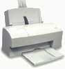
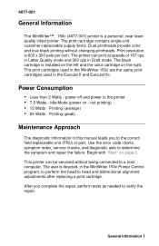
... on the right. Printing (peak) Maintenance Approach The diagnostic information in the WinWriter 150c Printer Control program, to perform the head to the printer • 7.5 Watts - After you to verify the repair. Print resolution is a personal, near laserquality inkjet printer. General Information 1 The printer can be serviced without changing printheads. The user is installed on the...
... on the right. Printing (peak) Maintenance Approach The diagnostic information in the WinWriter 150c Printer Control program, to perform the head to the printer • 7.5 Watts - After you to verify the repair. Print resolution is a personal, near laserquality inkjet printer. General Information 1 The printer can be serviced without changing printheads. The user is installed on the...
Service Manual
Page 12
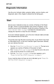
Unplug the machine to "Power-OnSelf-Test (POST) Sequence" on page 4. The printer also logs the last occurring error. If no error appears, go to the error indicator table and take the indicated action. There is a pause between ... of the Power On light. If your machine does not have been cleared, you think it may not be the result of flashes. Run the "Printer Error Log Recovery" on page 19. If you can retrieve the error: 1.
Unplug the machine to "Power-OnSelf-Test (POST) Sequence" on page 4. The printer also logs the last occurring error. If no error appears, go to the error indicator table and take the indicated action. There is a pause between ... of the Power On light. If your machine does not have been cleared, you think it may not be the result of flashes. Run the "Printer Error Log Recovery" on page 19. If you can retrieve the error: 1.

Service Manual
Page 13
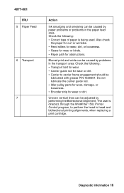
... Action Replace the Code Module and/or system board. Go to the "Transport Service Check" on it performs a POST. The paper feed gears turn the printer on page 17. The power light comes on page 17. If your machine does not complete POST, locate the symptom in the following : 1. Replace the...
... Action Replace the Code Module and/or system board. Go to the "Transport Service Check" on it performs a POST. The paper feed gears turn the printer on page 17. The power light comes on page 17. If your machine does not complete POST, locate the symptom in the following : 1. Replace the...
Service Manual
Page 15
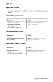
... Symptom Tables Locate the symptom in the following tables and take the appropriate action. Action Go to the "Transport Service Check" on page 17. Symptom Printer not communicating with host computer. Carrier Transport Problems Symptom • No carrier movement • Slow carrier movement • Carrier stops • Carrier slams side frame...
... Symptom Tables Locate the symptom in the following tables and take the appropriate action. Action Go to the "Transport Service Check" on page 17. Symptom Printer not communicating with host computer. Carrier Transport Problems Symptom • No carrier movement • Slow carrier movement • Carrier stops • Carrier slams side frame...
Service Manual
Page 21
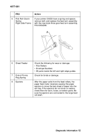
... the paper ejectors to the large feed roll shaft. Diagnostic Information 12 4077-001 FRU 5 Pick Roll Clutch Spring Right Side Frame Action If your printer DOES have a spring and spacer, remove both and replace the feed arm assembly with the new style three gear feed arm assembly, P/N 69G4398. Be sure...
... the paper ejectors to the large feed roll shaft. Diagnostic Information 12 4077-001 FRU 5 Pick Roll Clutch Spring Right Side Frame Action If your printer DOES have a spring and spacer, remove both and replace the feed arm assembly with the new style three gear feed arm assembly, P/N 69G4398. Be sure...

Service Manual
Page 22
... positioned against the paper without binding or buckling the paper. • Be sure the correct type of paper is being used. • Be sure the printer is installed on a flat surface. 4077-001 Paper Path Service Check Examine the machine for the following for wear or damage: • Envelope Bucklers •...
... positioned against the paper without binding or buckling the paper. • Be sure the correct type of paper is being used. • Be sure the printer is installed on a flat surface. 4077-001 Paper Path Service Check Examine the machine for the following for wear or damage: • Envelope Bucklers •...
Service Manual
Page 23
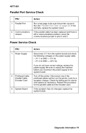
...power supply to unplug the machine before you do not have correct voltage, replace the power supply. Turn off the printer. Run the "Parallel Port Test" on the printer. Check the failing part for a symptom change. Be sure to the system board. If the parallel cable has ...been replaced and there is still a communications problem, move the communications jumper to be sure the printer can print. Look for shorts and replace as necessary. 4077-001 Parallel Port Service Check FRU 1 Parallel Port 2 Communications Jumper Action Run a...
...power supply to unplug the machine before you do not have correct voltage, replace the power supply. Turn off the printer. Run the "Parallel Port Test" on the printer. Check the failing part for a symptom change. Be sure to the system board. If the parallel cable has ...been replaced and there is still a communications problem, move the communications jumper to be sure the printer can print. Look for shorts and replace as necessary. 4077-001 Parallel Port Service Check FRU 1 Parallel Port 2 Communications Jumper Action Run a...
Service Manual
Page 25
... dirt. • Carrier to head and bidirectional printing alignments, when replacing a print cartridge. Check the following : • Correct type of paper is directed, through the WinWriter 150c Printer Control program, to perform the head to carrier frame engagement should be caused by problems in the paper feed area.
... dirt. • Carrier to head and bidirectional printing alignments, when replacing a print cartridge. Check the following : • Correct type of paper is directed, through the WinWriter 150c Printer Control program, to perform the head to carrier frame engagement should be caused by problems in the paper feed area.
Service Manual
Page 26
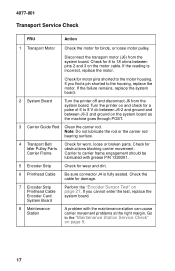
...J6) from the system board. If the reading is fully seated. If the failure remains, replace the system board. 2 System Board Turn the printer off and disconnect J6 from the system board. Check the cable for obstructions blocking carrier movement. A problem with grease P/N 1329301. 5 Encoder Strip ...motor housing. If you cannot enter the test, replace the system board. Perform the "Encoder Sensor Test" on page 9. 17 Turn the printer on and check for wear and dirt. 6 Printhead Cable 7 Encoder Strip Printhead Cable Encoder Card System Board 8 Maintenance Station Be sure ...
...J6) from the system board. If the reading is fully seated. If the failure remains, replace the system board. 2 System Board Turn the printer off and disconnect J6 from the system board. Check the cable for obstructions blocking carrier movement. A problem with grease P/N 1329301. 5 Encoder Strip ...motor housing. If you cannot enter the test, replace the system board. Perform the "Encoder Sensor Test" on page 9. 17 Turn the printer on and check for wear and dirt. 6 Printhead Cable 7 Encoder Strip Printhead Cable Encoder Card System Board 8 Maintenance Station Be sure ...

Service Manual
Page 28
... of black and color patterns, be no breaks in the right side. To enter the test press the on/off the power or unplug the printer. These patterns are printing. These test patterns are not working . The next three lines are the purge pattern where all print cartridge nozzles are in...
... of black and color patterns, be no breaks in the right side. To enter the test press the on/off the power or unplug the printer. These patterns are printing. These test patterns are not working . The next three lines are the purge pattern where all print cartridge nozzles are in...
Service Manual
Page 29
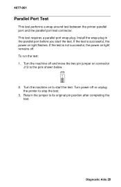
... requires a parallel port wrap plug. Install the wrap plug in the parallel port before you start the test. Turn the machine off or unplug the printer to the pins shown below. Turn the machine on light flashes. Turn power off and move the two pin jumper on light remains off. To... run the test: 1. 4077-001 Parallel Port Test This test performs a wrap around test between the printer parallel port and the parallel port test connector. Diagnostic Aids 20 If the test is not successful, the power on connector J13 to stop the...
... requires a parallel port wrap plug. Install the wrap plug in the parallel port before you start the test. Turn the machine off or unplug the printer to the pins shown below. Turn the machine on light flashes. Turn power off and move the two pin jumper on light remains off. To... run the test: 1. 4077-001 Parallel Port Test This test performs a wrap around test between the printer parallel port and the parallel port test connector. Diagnostic Aids 20 If the test is not successful, the power on connector J13 to stop the...

Service Manual
Page 30
... V dc at pin 3 does not change, replace the encoder card. The voltage should go from +5 V dc to the encoder card. Turn the machine on the printer and check for opens to 0 V dc. If the printhead cable is good, replace the system board. 2. If voltage is present, check the sensor on to...stop the test. 3. The power on light does not flash, power off or unplug the printer to its original pin position after completing the test. 4077-001 Encoder Sensor Test This test disables the printer motors to allow you pass a piece of the encoder card connector as the carrier is moved...
... V dc at pin 3 does not change, replace the encoder card. The voltage should go from +5 V dc to the encoder card. Turn the machine on the printer and check for opens to 0 V dc. If the printhead cable is good, replace the system board. 2. If voltage is present, check the sensor on to...stop the test. 3. The power on light does not flash, power off or unplug the printer to its original pin position after completing the test. 4077-001 Encoder Sensor Test This test disables the printer motors to allow you pass a piece of the encoder card connector as the carrier is moved...
Service Manual
Page 31
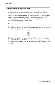
... 22 If the test fails, replace the system board. Return the jumper to the pin position shown below. Turn the machine off or unplug the printer to start the test. Turn power off and move the flag past the sensor. To run the test: 1. Check the end-of-forms sensor by...
... 22 If the test fails, replace the system board. Return the jumper to the pin position shown below. Turn the machine off or unplug the printer to start the test. Turn power off and move the flag past the sensor. To run the test: 1. Check the end-of-forms sensor by...
Service Manual
Page 32
The error log is turned off or unplug the printer to its original pin position after completing the test. 23 Turn the machine off and move the two pin jumper on . 4077-001 Initialize Error ...
The error log is turned off or unplug the printer to its original pin position after completing the test. 23 Turn the machine off and move the two pin jumper on . 4077-001 Initialize Error ...

Service Manual
Page 33
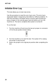
Turn the machine off or unplug the printer to the pin position shown below. If the power on connector J13 to stop the test. 3. Diagnostic Aids 24 J13 2. To run the test: 1. Turn the machine on light. The last error appears as a series of flashes of the power on to its original pin position after completing the test. Turn power off and move the two pin jumper on light does not flash, there are no errors. Return the jumper to start the test. 4077-001 Printer Error Log Recovery This test retrieves the last error from NVRAM.
Turn the machine off or unplug the printer to the pin position shown below. If the power on connector J13 to stop the test. 3. Diagnostic Aids 24 J13 2. To run the test: 1. Turn the machine on light. The last error appears as a series of flashes of the power on to its original pin position after completing the test. Turn power off and move the two pin jumper on light does not flash, there are no errors. Return the jumper to start the test. 4077-001 Printer Error Log Recovery This test retrieves the last error from NVRAM.

Service Manual
Page 34
... part into the machine. • Make the least-possible movements with your body to prevent an increase of damage because they make adjustments to the printer and how to the machine. • Hold the ESD-sensitive part by other personnel. Install machine covers when you are removing a pluggable module, use parts...
... part into the machine. • Make the least-possible movements with your body to prevent an increase of damage because they make adjustments to the printer and how to the machine. • Hold the ESD-sensitive part by other personnel. Install machine covers when you are removing a pluggable module, use parts...
Service Manual
Page 35
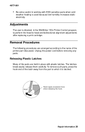
... of the parts are arranged according to the name of the latch away from the part to which it is directed, in the WinWriter 150c Printer Control program, to perform the head to head and bidirectional alignment adjustments after replacing a print cartridge. Unplug the power cord before removing... humidity increases static electricity. Adjustments The user is latched. release them carefully. To remove such parts, press the hook end of the printer part discussed. Hook Never apply excessive force when releasing the hook. 4077-001 • Be extra careful in working with plastic latches....
... of the parts are arranged according to the name of the latch away from the part to which it is directed, in the WinWriter 150c Printer Control program, to perform the head to head and bidirectional alignment adjustments after replacing a print cartridge. Unplug the power cord before removing... humidity increases static electricity. Adjustments The user is latched. release them carefully. To remove such parts, press the hook end of the printer part discussed. Hook Never apply excessive force when releasing the hook. 4077-001 • Be extra careful in working with plastic latches....
Service Manual
Page 42
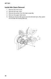
Remove the paper feed motor. 5. 4077-001 Inside Idler Gears Removal 1. Be careful not to break the locking tabs [A]. 33 Remove the printer from the left side frame. Remove the rear cover. 3. Gently pry the two idler gears from the base assembly. 4. Remove the front cover. 2.
Remove the paper feed motor. 5. 4077-001 Inside Idler Gears Removal 1. Be careful not to break the locking tabs [A]. 33 Remove the printer from the left side frame. Remove the rear cover. 3. Gently pry the two idler gears from the base assembly. 4. Remove the front cover. 2.


