C77x - Setup Guide
Page 6
... Getting started 7 Conventions ...7 Using this book ...7 Turning off the printer ...7 Selecting a location for your printer and MFP 7 Customizing your MFP option ...8 Drivers and options ...9 Where to begin ...9 Chapter 2: Caster base setup 10 Installing the caster base ...10 Installing the scanner shelf ......the printer 16 Removing the print cartridge packaging ...16 Loading paper ...18 Chapter 6: Installing printer memory or option cards 19 Accessing the printer system board ...19 Installing a memory card ...20 Installing a firmware card ...21 Installing the interface card ...22 Replacing...
... Getting started 7 Conventions ...7 Using this book ...7 Turning off the printer ...7 Selecting a location for your printer and MFP 7 Customizing your MFP option ...8 Drivers and options ...9 Where to begin ...9 Chapter 2: Caster base setup 10 Installing the caster base ...10 Installing the scanner shelf ......the printer 16 Removing the print cartridge packaging ...16 Loading paper ...18 Chapter 6: Installing printer memory or option cards 19 Accessing the printer system board ...19 Installing a memory card ...20 Installing a firmware card ...21 Installing the interface card ...22 Replacing...
C77x - Setup Guide
Page 20
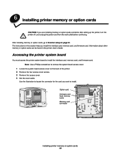
...section help you install the interface card, memory card, and firmware card. After installing memory or option cards, go to remove the system board access cover. 1 Locate the system board access cover on page 24. Option card Firmware and flash memory cards Memory card connector Installing printer memory or... 3 Remove the access cover. 4 Set the cover aside. Accessing the printer system board You must access the printer system board to locate the connector for the card you are installing memory or option cards sometime after setting up the printer, turn the printer off, and unplug the power...
...section help you install the interface card, memory card, and firmware card. After installing memory or option cards, go to remove the system board access cover. 1 Locate the system board access cover on page 24. Option card Firmware and flash memory cards Memory card connector Installing printer memory or... 3 Remove the access cover. 4 Set the cover aside. Accessing the printer system board You must access the printer system board to locate the connector for the card you are installing memory or option cards sometime after setting up the printer, turn the printer off, and unplug the power...
C77x - Setup Guide
Page 21
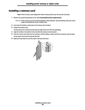
... of the card with the printer. 1 Remove the system board access cover. (See Accessing the printer system board.) Warning: Printer memory cards are easily damaged by static electricity. Installing printer memory or option cards Installing a memory card Note: Printer memory cards designed for other Lexmark printers may require some force to fully seat the...
... of the card with the printer. 1 Remove the system board access cover. (See Accessing the printer system board.) Warning: Printer memory cards are easily damaged by static electricity. Installing printer memory or option cards Installing a memory card Note: Printer memory cards designed for other Lexmark printers may require some force to fully seat the...
C77x - Setup Guide
Page 22
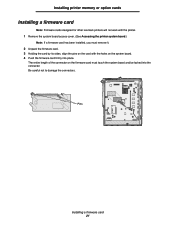
... align the pins on the system board. 4 Push the firmware card firmly into the connector. Be careful not to damage the connectors. Installing printer memory or option cards Installing a firmware card Note: Firmware cards designed for other Lexmark printers will not work with the holes... on the card with the printer. 1 Remove the system board access cover. (See Accessing the printer system board.) Note: If a firmware card...
... align the pins on the system board. 4 Push the firmware card firmly into the connector. Be careful not to damage the connectors. Installing printer memory or option cards Installing a firmware card Note: Firmware cards designed for other Lexmark printers will not work with the holes... on the card with the printer. 1 Remove the system board access cover. (See Accessing the printer system board.) Note: If a firmware card...
C77x - Setup Guide
Page 23
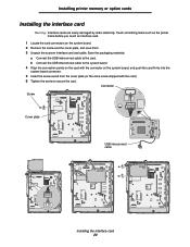
.... Installing printer memory or option cards Installing the interface card Warning: Interface cards are easily damaged by static electricity. Touch something metal such as the printer frame before you touch an interface card. 1 Locate the card connectors on the system board, and push the card ...the scanner interface card and cable. a Connect the USB interconnect cable to secure the card. b Connect the USB interconnect cable to the system board. 4 Align the connection points on the card with the card). 6 Tighten the screw to the card. Connector Screw Cover plate USB interconnect...
.... Installing printer memory or option cards Installing the interface card Warning: Interface cards are easily damaged by static electricity. Touch something metal such as the printer frame before you touch an interface card. 1 Locate the card connectors on the system board, and push the card ...the scanner interface card and cable. a Connect the USB interconnect cable to secure the card. b Connect the USB interconnect cable to the system board. 4 Align the connection points on the card with the card). 6 Tighten the screw to the card. Connector Screw Cover plate USB interconnect...
C77x - Setup Guide
Page 24
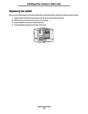
Installing printer memory or option cards Replacing the shield After you have installed options on the printer system board, follow these steps to reattach the shield and close the doors. 1 Align the slots at the top of the access cover with the screws near the top of the printer. 2 Slide the cover up under the top cover lip as far as it will go. 3 Insert and tighten the screws at the top of the cover. 4 Insert and tighten the screws at the bottom of the cover. Replacing the shield 23
Installing printer memory or option cards Replacing the shield After you have installed options on the printer system board, follow these steps to reattach the shield and close the doors. 1 Align the slots at the top of the access cover with the screws near the top of the printer. 2 Slide the cover up under the top cover lip as far as it will go. 3 Insert and tighten the screws at the top of the cover. 4 Insert and tighten the screws at the bottom of the cover. Replacing the shield 23

C77x - User's Guide
Page 6
...print media ...63 Selecting print media ...67 Storing print media ...71 Avoiding jams ...71 Chapter 9: Installing and removing options 73 Accessing the printer system board ...73 Installing a memory card ...74 Installing a firmware card ...75 Installing the interface card ...76 Replacing the access... cover plate ...77 Chapter 10: Maintaining the MFP 78 Determining the status of supplies ...79 Ordering supplies ...79 Recycling Lexmark products ...80...
...print media ...63 Selecting print media ...67 Storing print media ...71 Avoiding jams ...71 Chapter 9: Installing and removing options 73 Accessing the printer system board ...73 Installing a memory card ...74 Installing a firmware card ...75 Installing the interface card ...76 Replacing the access... cover plate ...77 Chapter 10: Maintaining the MFP 78 Determining the status of supplies ...79 Ordering supplies ...79 Recycling Lexmark products ...80...

C77x - User's Guide
Page 73
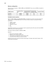
... access the printer system board to remove the system board access cover. 1 Locate the system board access cover on the back of the printer. 2 Remove the four access cover screws. 3 Remove the access cover. 4 Set the cover aside. Option card Firmware and flash memory cards Memory card connector Installing and removing options 73 Information about...
... access the printer system board to remove the system board access cover. 1 Locate the system board access cover on the back of the printer. 2 Remove the four access cover screws. 3 Remove the access cover. 4 Set the cover aside. Option card Firmware and flash memory cards Memory card connector Installing and removing options 73 Information about...

C77x - User's Guide
Page 74
Save the packaging. 4 Align the notches on the bottom of the card with the printer. 1 Remove the system board access cover. (See Accessing the printer system board.) Warning: Printer memory cards are easily damaged by static electricity. It may not work with the notches on the connector. 5 Push... into the connector until the latches on either end of the connector snap into place. Installing and removing options Installing a memory card Note: Printer memory cards designed for other Lexmark printers may require some force to fully seat the card. 6 Make sure each latch fits over the ...
Save the packaging. 4 Align the notches on the bottom of the card with the printer. 1 Remove the system board access cover. (See Accessing the printer system board.) Warning: Printer memory cards are easily damaged by static electricity. It may not work with the notches on the connector. 5 Push... into the connector until the latches on either end of the connector snap into place. Installing and removing options Installing a memory card Note: Printer memory cards designed for other Lexmark printers may require some force to fully seat the card. 6 Make sure each latch fits over the ...

C77x - User's Guide
Page 75
... card with the holes on the system board. 4 Push the firmware card firmly into the connector. Be careful not to damage the connectors. Installing and removing options Installing a firmware card Note: Firmware cards designed for other Lexmark printers will not work with the printer.... 1 Remove the system board access cover. (See Accessing the printer system board.) Note: If a firmware card has been installed...
... card with the holes on the system board. 4 Push the firmware card firmly into the connector. Be careful not to damage the connectors. Installing and removing options Installing a firmware card Note: Firmware cards designed for other Lexmark printers will not work with the printer.... 1 Remove the system board access cover. (See Accessing the printer system board.) Note: If a firmware card has been installed...

C77x - User's Guide
Page 76
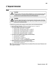
Connector USB interconnect cable Installing the interface card 76 Touch something metal such as the printer frame before you touch an interface card. 1 Remove the system board access cover. 2 Remove the screw and cover plate, and save them. Installing and removing options Installing the interface card Warning: Interface cards are easily damaged by static electricity. Save the packaging materials. b Connect the USB interconnect cable to the card. a Connect the USB interconnect cable to the system board. Screw Cover plate 3 Unpack the scanner interface card and cable.
Connector USB interconnect cable Installing the interface card 76 Touch something metal such as the printer frame before you touch an interface card. 1 Remove the system board access cover. 2 Remove the screw and cover plate, and save them. Installing and removing options Installing the interface card Warning: Interface cards are easily damaged by static electricity. Save the packaging materials. b Connect the USB interconnect cable to the card. a Connect the USB interconnect cable to the system board. Screw Cover plate 3 Unpack the scanner interface card and cable.

C77x - User's Guide
Page 77
Replacing the access cover plate After you have installed options on the system board, and push the card firmly into the system board connector. 5 Insert and tighten the screws to reattach the access cover plate. 1 Align the slots at the top and bottom of the cover. Replacing the ...access cover plate 77 Installing and removing options 4 Align the connection points on the card with the screws near...
Replacing the access cover plate After you have installed options on the system board, and push the card firmly into the system board connector. 5 Insert and tighten the screws to reattach the access cover plate. 1 Align the slots at the top and bottom of the cover. Replacing the ...access cover plate 77 Installing and removing options 4 Align the connection points on the card with the screws near...

C77x - User's Guide
Page 110
.... Notices China RoHS Part Name Hazardous Substances or Elements Lead (Pb) Mercury (Hg) Cadmium Hexavalent (Cd) Chromium (CrVI) Polybrominated Polybrominated biphenyl (PBB) diphenylether (PBDE) Circuit boards X O O O O O Power supply X O O O O O Connectors X O O O O O Mechanical assemblies - shafts, X O O O O O rollers Mechanical assemblies - others X O O O O O Scanner assembly O X O O O O LCD display O X O O O O O: Indicates that the content of the toxic and hazardous substance in...
.... Notices China RoHS Part Name Hazardous Substances or Elements Lead (Pb) Mercury (Hg) Cadmium Hexavalent (Cd) Chromium (CrVI) Polybrominated Polybrominated biphenyl (PBB) diphenylether (PBDE) Circuit boards X O O O O O Power supply X O O O O O Connectors X O O O O O Mechanical assemblies - shafts, X O O O O O rollers Mechanical assemblies - others X O O O O O Scanner assembly O X O O O O LCD display O X O O O O O: Indicates that the content of the toxic and hazardous substance in...
Service Manual
Page 7
5061 Auto Color Adjust 3-34 Paper Prompts 3-34 Env Prompts 3-34 Font Sharpening 3-34 Jobs On Disk 3-35 Disk Encryption 3-35 Exit Config Menu 3-35 Paper jams 3-36 Identifying jams 3-36 Access doors and trays 3-36 Understanding jam messages 3-37 Paper jam messages 3-37 Clearing the entire paper path 3-38 Area A 3-38 Area B 3-39 Area C 3-39 Area D 3-40 Area T1 3-40 Area E 3-41 Area T
5061 Auto Color Adjust 3-34 Paper Prompts 3-34 Env Prompts 3-34 Font Sharpening 3-34 Jobs On Disk 3-35 Disk Encryption 3-35 Exit Config Menu 3-35 Paper jams 3-36 Identifying jams 3-36 Access doors and trays 3-36 Understanding jam messages 3-37 Paper jam messages 3-37 Clearing the entire paper path 3-38 Area A 3-38 Area B 3-39 Area C 3-39 Area D 3-40 Area T1 3-40 Area E 3-41 Area T
Service Manual
Page 8
...removal 4-62 Multipurpose feeder (MPF) motor removal 4-64 Nip relief handle removal 4-65 Operator panel assembly removal 4-68 Outer system board shield removal 4-69 Pick rolls removal 4-70 Printhead removal and adjustments 4-72 Mechanical alignment 4-72 Black printhead electronic alignment 4-77 ... cable removal 4-87 S2/narrow media/transparency/multipurpose feeder sensors removal 4-88 Second transfer roll removal 4-88 System board removal 4-89 Transfer HVPS board removal 4-91 Transfer plate assembly removal 4-94 Vacuum transport belt (VTB) removal 4-95 Vacuum transport belt (VTB...
...removal 4-62 Multipurpose feeder (MPF) motor removal 4-64 Nip relief handle removal 4-65 Operator panel assembly removal 4-68 Outer system board shield removal 4-69 Pick rolls removal 4-70 Printhead removal and adjustments 4-72 Mechanical alignment 4-72 Black printhead electronic alignment 4-77 ... cable removal 4-87 S2/narrow media/transparency/multipurpose feeder sensors removal 4-88 Second transfer roll removal 4-88 System board removal 4-89 Transfer HVPS board removal 4-91 Transfer plate assembly removal 4-94 Vacuum transport belt (VTB) removal 4-95 Vacuum transport belt (VTB...
Service Manual
Page 9
5061 Low voltage power supply (LVPS 5-23 LVPS cable connectors to system board 5-23 LVPS fuser connectors 5-24 Media size sensing board 5-25 High-capacity input tray (HCIT 5-26 StapleSmart finisher 5-28 Preventive maintenance 6-1 Safety inspection guide 6-1 Scheduled maintenance 6-1 Standard fusers...-cabling interconnections 4 7-41 Assembly 27: Output expander 7-42 Assembly 28: 5-Bin mailbox 7-46 Assembly 29: 500-Sheet drawer option 7-50 Assembly 30: Duplex option 7-54 Assembly 31: High-capacity input tray (HCIT 7-58 Assembly 32: StapleSmart finisher 7-62 Assembly 33: Envelope...
5061 Low voltage power supply (LVPS 5-23 LVPS cable connectors to system board 5-23 LVPS fuser connectors 5-24 Media size sensing board 5-25 High-capacity input tray (HCIT 5-26 StapleSmart finisher 5-28 Preventive maintenance 6-1 Safety inspection guide 6-1 Scheduled maintenance 6-1 Standard fusers...-cabling interconnections 4 7-41 Assembly 27: Output expander 7-42 Assembly 28: 5-Bin mailbox 7-46 Assembly 29: 500-Sheet drawer option 7-50 Assembly 30: Duplex option 7-54 Assembly 31: High-capacity input tray (HCIT 7-58 Assembly 32: StapleSmart finisher 7-62 Assembly 33: Envelope...
Service Manual
Page 28
... Memory Options available are available from Lexmark. The memory options are 168-pin synchronous DRAM DIMMs (dual in 128MB, 256MB, and 512MB DIMM. Expansion • Memory slot for extra flash or DRAM • Expansion slot for optional interface cards • Code expansion slot (application solution firmware cards) • On-board hard disk interface (for optional hard...
... Memory Options available are available from Lexmark. The memory options are 168-pin synchronous DRAM DIMMs (dual in 128MB, 256MB, and 512MB DIMM. Expansion • Memory slot for extra flash or DRAM • Expansion slot for optional interface cards • Code expansion slot (application solution firmware cards) • On-board hard disk interface (for optional hard...
Service Manual
Page 43
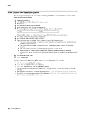
... information Start CAUTION Unplug the power cord from the electrical outlet before lifting the printer. Disconnect any cable or electronic board or assembly for assistance. Make sure your next level of support for personal safety and to prevent damage to lift ...117 - "Understanding the printer operator panel" on page 2-124 - Check the "POR (Power-On Reset) sequence" on page 2-4 - "Symptom table-HCIT 2000-sheet option" on page 2-2 • Do you have a symptom, rather than an error message? - Diagnostic information 2-1 "1xx service errors" on page 2-14 for the following ...
... information Start CAUTION Unplug the power cord from the electrical outlet before lifting the printer. Disconnect any cable or electronic board or assembly for assistance. Make sure your next level of support for personal safety and to prevent damage to lift ...117 - "Understanding the printer operator panel" on page 2-124 - Check the "POR (Power-On Reset) sequence" on page 2-4 - "Symptom table-HCIT 2000-sheet option" on page 2-2 • Do you have a symptom, rather than an error message? - Diagnostic information 2-1 "1xx service errors" on page 2-14 for the following ...
Service Manual
Page 44
...is below 60° C. • When coming out of power saver if power saver has been active for the base machine with no paper handling options installed. 1. Color calibration may appear during the POR sequence for eight hours or longer. • If the printer is turned on . 4. Various ...messages may be initiated. Power the machine on. 2. +5 V LED (Power ON) on the system board comes on the display. 8. While loading code, dots scroll across the display. 6. The image of a clock face appears on . 3. This is displayed if one ...
...is below 60° C. • When coming out of power saver if power saver has been active for the base machine with no paper handling options installed. 1. Color calibration may appear during the POR sequence for eight hours or longer. • If the printer is turned on . 4. Various ...messages may be initiated. Power the machine on. 2. +5 V LED (Power ON) on the system board comes on the display. 8. While loading code, dots scroll across the display. 6. The image of a clock face appears on . 3. This is displayed if one ...
Service Manual
Page 49
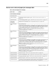
... "Printhead diagnostics" on page 3-1. Go to "122.02 error code service check" on page 2-19. Fuser over temperature-go to "System board" on page 5-8. Fuser cold-go to "System board" on page 5-8. Go to "122.04 error code service check" on page 2-20. If the cables are connected correctly to the system... Error 122.02 Fuser Error 122.03 Fuser Error 122.04 Fuser Error 122.05 Fuser Error ITU belt track direction problem-go to "System board" on page 5-8. See "ITU assembly removal" on page 2-17. Fuser error-go to "100.02 ITU error service check" on page 4-49. Check for the...
... "Printhead diagnostics" on page 3-1. Go to "122.02 error code service check" on page 2-19. Fuser over temperature-go to "System board" on page 5-8. Fuser cold-go to "System board" on page 5-8. Go to "122.04 error code service check" on page 2-20. If the cables are connected correctly to the system... Error 122.02 Fuser Error 122.03 Fuser Error 122.04 Fuser Error 122.05 Fuser Error ITU belt track direction problem-go to "System board" on page 5-8. See "ITU assembly removal" on page 2-17. Fuser error-go to "100.02 ITU error service check" on page 4-49. Check for the...


