User's Guide
Page 66
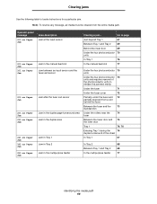
Note: To resolve any message, all media must be cleared from a slot behind the fuser Between the fuser and the 73 standard bin Under the rollers near the 74 fuser Between the lower door and 75 the inner door Tray 1 76, 76 Entering Tray 1 during the 76 duplex turnaround of the ...
Note: To resolve any message, all media must be cleared from a slot behind the fuser Between the fuser and the 73 standard bin Under the rollers near the 74 fuser Between the lower door and 75 the inner door Tray 1 76, 76 Entering Tray 1 during the 76 duplex turnaround of the ...
User's Guide
Page 74
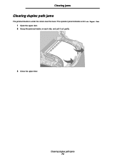
Clearing duplex path jams 74 The operator panel indicates a 203.xx Paper Jam. 1 Open the upper door. 2 Grasp the jammed media on each side, and pull it out gently. 3 Close the upper door. Clearing jams Clearing duplex path jams The jammed media is under the rollers near the fuser.
Clearing duplex path jams 74 The operator panel indicates a 203.xx Paper Jam. 1 Open the upper door. 2 Grasp the jammed media on each side, and pull it out gently. 3 Close the upper door. Clearing jams Clearing duplex path jams The jammed media is under the rollers near the fuser.
Service Manual
Page 15
... Power-On Self Test Pulse Width Modulation Raster Imaging Processor Synchronous Dual Random Access Memory Single Inline Memory Module Static Random Access Memory Toner Adder Roller Volts alternating current Volts direct current Yellow 1-14 Service Manual
... Power-On Self Test Pulse Width Modulation Raster Imaging Processor Synchronous Dual Random Access Memory Single Inline Memory Module Static Random Access Memory Toner Adder Roller Volts alternating current Volts direct current Yellow 1-14 Service Manual

Service Manual
Page 20
... the display. 13. The main drive motor turns on . 3. Diagnostic information 2-5 The main fan turns on . 14. The operator panel display clears again. 8. The exit rollers turn the printer on . 2. 5022-xxx Power-on self test (POST) sequence When you turn . 16. The operator panel display clears. 6. Check for correct POST...
... the display. 13. The main drive motor turns on . 3. Diagnostic information 2-5 The main fan turns on . 14. The operator panel display clears again. 8. The exit rollers turn the printer on . 2. 5022-xxx Power-on self test (POST) sequence When you turn . 16. The operator panel display clears. 6. Check for correct POST...

Service Manual
Page 107
5022-xxx Theory of operation Paper path Paper exit flag Fuser Transfer belt System card Bump roller align Input flag Paper pick mechanism Duplex MPF pick 3-30 Service Manual
5022-xxx Theory of operation Paper path Paper exit flag Fuser Transfer belt System card Bump roller align Input flag Paper pick mechanism Duplex MPF pick 3-30 Service Manual

Service Manual
Page 112
... flag Fuser backup roll Fuser exit idler roll Fuser hot roll Diagnostic aids 3-35 Once the print media reaches the fuser output drive roll, the roller pushes the print media into the output bin. 5022-xxx Once the print media exits the transfer belt, it enters the fuser where heat and... bond the toner permanently to turn and pull the print media through the paper path until it to the fuser output drive roll. The fuser rollers continue to the media. The exit drive roll pulls the print media from the fuser...
... flag Fuser backup roll Fuser exit idler roll Fuser hot roll Diagnostic aids 3-35 Once the print media reaches the fuser output drive roll, the roller pushes the print media into the output bin. 5022-xxx Once the print media exits the transfer belt, it enters the fuser where heat and... bond the toner permanently to turn and pull the print media through the paper path until it to the fuser output drive roll. The fuser rollers continue to the media. The exit drive roll pulls the print media from the fuser...

Service Manual
Page 113
The media is then routed down through the duplex path until it clears the paper exit flag and then reverses the rotation of the roller in this position, it to either the output bin or the duplex paper path. 3-36 Service Manual Fuser output drive roll Paper exit flag The ...
The media is then routed down through the duplex path until it clears the paper exit flag and then reverses the rotation of the roller in this position, it to either the output bin or the duplex paper path. 3-36 Service Manual Fuser output drive roll Paper exit flag The ...

Service Manual
Page 114
Paper pick mechanism drive When printing from Tray 1 or Tray 2, the paper pick motor drives the paper pick gears which causes the pick roller to turn . Diagnostic aids 3-37 During an MPF print, the paper pick motor drives the swing arm assembly for the MPF and causes the MPF paper pick roller to turn . 5022-xxx Mechanical drive In order for the print media to move through the paper path, there are illustrated and discussed in the following paragraphs. The drives for these components are several drive motors that supply the mechanical power to the rollers discussed previously.
Paper pick mechanism drive When printing from Tray 1 or Tray 2, the paper pick motor drives the paper pick gears which causes the pick roller to turn . Diagnostic aids 3-37 During an MPF print, the paper pick motor drives the swing arm assembly for the MPF and causes the MPF paper pick roller to turn . 5022-xxx Mechanical drive In order for the print media to move through the paper path, there are illustrated and discussed in the following paragraphs. The drives for these components are several drive motors that supply the mechanical power to the rollers discussed previously.

Service Manual
Page 117
5022-xxx Transfer belt drive The transfer belt unit receives drive from a motor located on the EP drive assembly. Outside Inside Transfer belt motor Coupler Fuser drive The fuser drive (motor) is open, the coupler for the transfer belt disengages. When the top access door is built into the fuser assembly and drives the fuser rollers to turn. 3-40 Service Manual
5022-xxx Transfer belt drive The transfer belt unit receives drive from a motor located on the EP drive assembly. Outside Inside Transfer belt motor Coupler Fuser drive The fuser drive (motor) is open, the coupler for the transfer belt disengages. When the top access door is built into the fuser assembly and drives the fuser rollers to turn. 3-40 Service Manual
Service Manual
Page 122
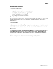
... : • The charge roll located in the photoconductor unit • The photoconductor drum located in the photoconductor unit • The toner adder roller (TAR) located in the toner cartridge • The developer roll located in the toner cartridge • The doctor blade located in the toner ...• The four transfer rolls located in the transfer belt Printhead assembly The printhead receives control and image data from the cartridge developer roller and then transferring the image to prepare it for the latent image "drawn" by the laser, it is responsible for transfer onto ...
... : • The charge roll located in the photoconductor unit • The photoconductor drum located in the photoconductor unit • The toner adder roller (TAR) located in the toner cartridge • The developer roll located in the toner cartridge • The doctor blade located in the toner ...• The four transfer rolls located in the transfer belt Printhead assembly The printhead receives control and image data from the cartridge developer roller and then transferring the image to prepare it for the latent image "drawn" by the laser, it is responsible for transfer onto ...
Service Manual
Page 125
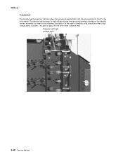
5022-xxx Transfer belt The transfer belt houses four transfer rollers that provide image transfer from the photoconductor drum to the print media. The transfer belt receives its high voltage charge through spring contacts located on the transfer contact assembly as well. This path is shown. Transfer belt high voltage path 3-48 Service Manual For the sake of simplicity, only one of the roller's high voltage paths is typical for the other three rollers as shown in the following illustration.
5022-xxx Transfer belt The transfer belt houses four transfer rollers that provide image transfer from the photoconductor drum to the print media. The transfer belt receives its high voltage charge through spring contacts located on the transfer contact assembly as well. This path is shown. Transfer belt high voltage path 3-48 Service Manual For the sake of simplicity, only one of the roller's high voltage paths is typical for the other three rollers as shown in the following illustration.

Service Manual
Page 134
...-sensitive part in its special bag. • Printer covers and metal tables are ready to install the part in revolving parts such as the gears, rollers and fan motor. • Never touch the terminals of static electricity from your clothing to unplug the printer from being accidentally touched by holding the...
...-sensitive part in its special bag. • Printer covers and metal tables are ready to install the part in revolving parts such as the gears, rollers and fan motor. • Never touch the terminals of static electricity from your clothing to unplug the printer from being accidentally touched by holding the...

Service Manual
Page 135
Handling • The optical photoconductor roller in the photoconductor unit exhibits the greatest light fatigue after being exposed to meet a printer alignment set at ...light over an extended period of time. Cover the photoconductor unit when you will have to contaminate the surface of the optical photoconductor roller with an oil-based solvent, fingerprints, and other foreign matter. • Do not scratch the surface of the repair procedures: ...4-2 Service Manual Never expose it from the printer. • Use care not to remove during some of the optical photoconductor roller.
Handling • The optical photoconductor roller in the photoconductor unit exhibits the greatest light fatigue after being exposed to meet a printer alignment set at ...light over an extended period of time. Cover the photoconductor unit when you will have to contaminate the surface of the optical photoconductor roller with an oil-based solvent, fingerprints, and other foreign matter. • Do not scratch the surface of the repair procedures: ...4-2 Service Manual Never expose it from the printer. • Use care not to remove during some of the optical photoconductor roller.

Service Manual
Page 175
Lower the bump aligner spring to relase the bump aligner spring. 3. Remove the paper tray. 2. 5022-xxx Bump aligner rollers and springs removal-models C53x See "Bump aligner roller and spring" on page 7-5 for the part number. 1. Push up and back to remove it. 4-42 Service Manual
Lower the bump aligner spring to relase the bump aligner spring. 3. Remove the paper tray. 2. 5022-xxx Bump aligner rollers and springs removal-models C53x See "Bump aligner roller and spring" on page 7-5 for the part number. 1. Push up and back to remove it. 4-42 Service Manual

Service Manual
Page 176
Remove the bump aligner roller. 5022-xxx Installation note: Make sure to support the bump aligner roller in the arms of the bump aligner spring. Repair information 4-43 4.
Remove the bump aligner roller. 5022-xxx Installation note: Make sure to support the bump aligner roller in the arms of the bump aligner spring. Repair information 4-43 4.
Service Manual
Page 228
... not working with your body to prevent an increase of static electricity from your clothing to be caught in revolving parts such as the gears, rollers and fan motor. • Never touch the terminals of electrical parts or high-voltage parts such as the high-voltage power supply. • After part...
... not working with your body to prevent an increase of static electricity from your clothing to be caught in revolving parts such as the gears, rollers and fan motor. • Never touch the terminals of electrical parts or high-voltage parts such as the high-voltage power supply. • After part...

Service Manual
Page 229
... photoconductor unit. Cover the photoconductor unit when you will have to contaminate the surface of the optical photoconductor roller with an oil-based solvent, fingerprints, and other foreign matter. • Do not scratch the surface of the optical photoconductor... roller. Handling • The optical photoconductor roller in the photoconductor unit exhibits the greatest light fatigue after being exposed to direct sunlight. Never expose it from the ...
... photoconductor unit. Cover the photoconductor unit when you will have to contaminate the surface of the optical photoconductor roller with an oil-based solvent, fingerprints, and other foreign matter. • Do not scratch the surface of the optical photoconductor... roller. Handling • The optical photoconductor roller in the photoconductor unit exhibits the greatest light fatigue after being exposed to direct sunlight. Never expose it from the ...

Service Manual
Page 269
Remove the paper tray. 2. Lower the bump aligner spring to relase the bump aligner spring. 3. 5022-xxx Bump aligner rollers and springs removal-models C53x See "Bump aligner roller and spring" on page 7-5 for the part number. 1. Push up and back to remove it. 4-42 Service Manual
Remove the paper tray. 2. Lower the bump aligner spring to relase the bump aligner spring. 3. 5022-xxx Bump aligner rollers and springs removal-models C53x See "Bump aligner roller and spring" on page 7-5 for the part number. 1. Push up and back to remove it. 4-42 Service Manual

Service Manual
Page 270
Repair information 4-43 Remove the bump aligner roller. 5022-xxx Installation note: Make sure to support the bump aligner roller in the arms of the bump aligner spring. 4.
Repair information 4-43 Remove the bump aligner roller. 5022-xxx Installation note: Make sure to support the bump aligner roller in the arms of the bump aligner spring. 4.

Service Manual
Page 352
... assembly, C524dn Front door assembly, C520n/C522n/C524n Duplex front door assembly, C530dn/C532dn/C534dn Front door assembly, C532n/C534n Deflector assembly, C53x Bump aligner roller and spring MPF swing arm assembly, C52x Left bellcrank assembly Paper pick mechanism assembly, C52x Paper pick mechanism assembly, C53x Bump aligner...
... assembly, C524dn Front door assembly, C520n/C522n/C524n Duplex front door assembly, C530dn/C532dn/C534dn Front door assembly, C532n/C534n Deflector assembly, C53x Bump aligner roller and spring MPF swing arm assembly, C52x Left bellcrank assembly Paper pick mechanism assembly, C52x Paper pick mechanism assembly, C53x Bump aligner...


