Service Manual
Page 13
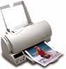
...7.5 Watts - not printing) • 12 Watts - Printing (average) • 25 Watts - The color print cartridge used to service both the IBM ExecJet II by Lexmark 4076 and the ExecJet IIc 4076 printers. The Ink Low and Busy lights will flash alternately to indicate to -right with a customer-replaceable print... cartridge containing the ink and the print head. power off and power to the printer. ...
...7.5 Watts - not printing) • 12 Watts - Printing (average) • 25 Watts - The color print cartridge used to service both the IBM ExecJet II by Lexmark 4076 and the ExecJet IIc 4076 printers. The Ink Low and Busy lights will flash alternately to indicate to -right with a customer-replaceable print... cartridge containing the ink and the print head. power off and power to the printer. ...
Service Manual
Page 32
...head cable - A broken line indicates one or more print nozzles are even breaks in poor contact between the print head cable and the print cartridge. Check the rubber backer for damage. Look for dirt and wear. check the goldplated contacts on page 25. Use only a clean dry cloth... to inspect it. • Rubber Backer - 4076-0XX Print Quality Service Check FRU OR PROCEDURE ACTION 1 Print Cartridge Be sure the machine has a known good print cartridge. 2 Print Head Carrier Assembly Reseat the print head cable in the diagonal line check the ...
...head cable - A broken line indicates one or more print nozzles are even breaks in poor contact between the print head cable and the print cartridge. Check the rubber backer for damage. Look for dirt and wear. check the goldplated contacts on page 25. Use only a clean dry cloth... to inspect it. • Rubber Backer - 4076-0XX Print Quality Service Check FRU OR PROCEDURE ACTION 1 Print Cartridge Be sure the machine has a known good print cartridge. 2 Print Head Carrier Assembly Reseat the print head cable in the diagonal line check the ...
Service Manual
Page 36
... printer. Use this test because the power off . Fonts downloaded to RAM cannot be attached to a host to be printed with a black print cartridge installed. This test prints a two-page demo pattern. You must hold the buttons until all RAM fonts. The button pattern is illustrated for the Hex... Print test procedure, the printer does not need to run the tests. 4076-0XX Diagnostic Aids 4 Use these diagnostic test procedures to check the overall quality of each test. Demo Test Perform this test with this ...
... printer. Use this test because the power off . Fonts downloaded to RAM cannot be attached to a host to be printed with a black print cartridge installed. This test prints a two-page demo pattern. You must hold the buttons until all RAM fonts. The button pattern is illustrated for the Hex... Print test procedure, the printer does not need to run the tests. 4076-0XX Diagnostic Aids 4 Use these diagnostic test procedures to check the overall quality of each test. Demo Test Perform this test with this ...
Service Manual
Page 37
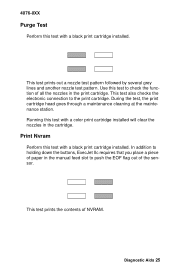
...lines and another nozzle test pattern. Print Nvram Perform this test with a black print cartridge installed. This test prints the contents of paper in the manual feed slot to the print cartridge. This test also checks the electronic connection to push the EOF flag out of all... in the print cartridge. Running this test to check the function of the sensor. During the test, the print cartridge head goes through a maintenance cleaning at the maintenance station. In addition to holding down the buttons, ExecJet IIc requires that you place a piece of NVRAM. 4076-0XX Purge Test...
...lines and another nozzle test pattern. Print Nvram Perform this test with a black print cartridge installed. This test prints the contents of paper in the manual feed slot to the print cartridge. This test also checks the electronic connection to push the EOF flag out of all... in the print cartridge. Running this test to check the function of the sensor. During the test, the print cartridge head goes through a maintenance cleaning at the maintenance station. In addition to holding down the buttons, ExecJet IIc requires that you place a piece of NVRAM. 4076-0XX Purge Test...
Service Manual
Page 38
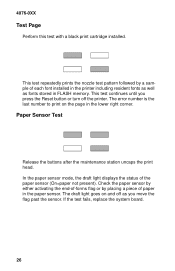
... Release the buttons after the maintenance station uncaps the print head. If the test fails, replace the system board. 26 4076-0XX Test Page Perform this test with a black print cartridge installed. In the paper sensor mode, the draft light displays the status of each font installed in the printer including resident...
... Release the buttons after the maintenance station uncaps the print head. If the test fails, replace the system board. 26 4076-0XX Test Page Perform this test with a black print cartridge installed. In the paper sensor mode, the draft light displays the status of each font installed in the printer including resident...
Service Manual
Page 39
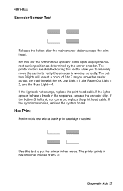
4076-0XX Encoder Sensor Test Release the button after the maintenance station uncaps the print head. The printer motors are disabled during this test with the ....If the lights appear to 7 as determined by the carrier encoder. For this test to manually move the carrier across the machine with a black print cartridge installed. Use this test the bottom three operator panel lights display the current carrier position as you to put the printer in the sequence, replace...
4076-0XX Encoder Sensor Test Release the button after the maintenance station uncaps the print head. The printer motors are disabled during this test with the ....If the lights appear to 7 as determined by the carrier encoder. For this test to manually move the carrier across the machine with a black print cartridge installed. Use this test the bottom three operator panel lights display the current carrier position as you to put the printer in the sequence, replace...
Service Manual
Page 41
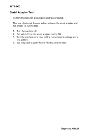
To run the test: 1. Turn the machine off. 2. 4076-0XX Serial Adapter Test Perform this test with a black print cartridge installed. Turn the machine on the serial adapter card to ON. 3. Set switch 10 on to print the test. You may have to press Forms Feed to print out the current switch settings and a test pattern. 4. Diagnostic Aids 29 This test checks out the connection between the serial adapter and the printer.
To run the test: 1. Turn the machine off. 2. 4076-0XX Serial Adapter Test Perform this test with a black print cartridge installed. Turn the machine on the serial adapter card to ON. 3. Set switch 10 on to print the test. You may have to press Forms Feed to print out the current switch settings and a test pattern. 4. Diagnostic Aids 29 This test checks out the connection between the serial adapter and the printer.
Service Manual
Page 43
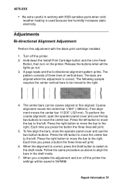
Hold down the Install Print Cartridge button and the Line Feed Button, then turn off the printer. 2. Coarse alignment moves the center bar 1/300" (.085mm). Adjustments Bi-directional Alignment Adjustment Perform .... Follow the same procedure as above to the draft mode. A page loads and the bi-directional alignment pattern prints. 4076-0XX • Be extra careful in working with the black print cartridge installed. 1. The bars are aligned when the adjustment is used because low humidity increases static electricity. To fine align the...
Hold down the Install Print Cartridge button and the Line Feed Button, then turn off the printer. 2. Coarse alignment moves the center bar 1/300" (.085mm). Adjustments Bi-directional Alignment Adjustment Perform .... Follow the same procedure as above to the draft mode. A page loads and the bi-directional alignment pattern prints. 4076-0XX • Be extra careful in working with the black print cartridge installed. 1. The bars are aligned when the adjustment is used because low humidity increases static electricity. To fine align the...
Service Manual
Page 46
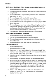
Remove the inside C-clip from the right. 34 Remove the top cover. 2. Remove the print cartridge. 3. Remove the paper load lever and shaft by prying up at each end of the rod, to lose the small gear on the left side .... 7. Remove the paper load lever from the carrier. 6. Be careful not to open the print head cable connectors on the carrier clears the encoder strip. 4076-0XX ASF Right And Left Edge Guide Assemblies Removal 1. Remove the auto sheet feed. 2. Remove the paper load lever knob from the right side of...
Remove the inside C-clip from the right. 34 Remove the top cover. 2. Remove the print cartridge. 3. Remove the paper load lever and shaft by prying up at each end of the rod, to lose the small gear on the left side .... 7. Remove the paper load lever from the carrier. 6. Be careful not to open the print head cable connectors on the carrier clears the encoder strip. 4076-0XX ASF Right And Left Edge Guide Assemblies Removal 1. Remove the auto sheet feed. 2. Remove the paper load lever knob from the right side of...
Service Manual
Page 47
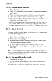
...Reach through the opening in the carrier transport motor frame. 3. When you carefully follow this procedure. 1. Carrier Transport Motor Removal 1. 4076-0XX Carrier Transport Belt Removal 1. Move the carrier in line with the opening and pull the belt from the carrier. 4. Open ... access cover. 2. With the carrier centered, carefully release the 2 carrier guide rod latches and lift the shaft slightly. 4. Remove the print cartridge. 3. Disconnect the carrier transport motor (J6) from the carrier transport motor pulley. 5. Repair Information 35 Remove the top cover. 2. Remove the...
...Reach through the opening in the carrier transport motor frame. 3. When you carefully follow this procedure. 1. Carrier Transport Motor Removal 1. 4076-0XX Carrier Transport Belt Removal 1. Move the carrier in line with the opening and pull the belt from the carrier. 4. Open ... access cover. 2. With the carrier centered, carefully release the 2 carrier guide rod latches and lift the shaft slightly. 4. Remove the print cartridge. 3. Disconnect the carrier transport motor (J6) from the carrier transport motor pulley. 5. Repair Information 35 Remove the top cover. 2. Remove the...
Service Manual
Page 51
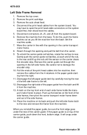
... from the 4 retainers in the left . 12. When you lift the machine from the right. 11. Be careful not to -rear. Remove the print cartridge. 3. Push up the rod until the sensor on the front of the side frames, then pivot the carrier transport motor frame down the front, bottom... edge. Move the carrier in line with the opening in the paper guide starting from the base. 4076-0XX Left Side Frame Removal 1. Gently push the carrier guide rod latches, at each side frame holds the transport motor frame in the carrier ...
... from the 4 retainers in the left . 12. When you lift the machine from the right. 11. Be careful not to -rear. Remove the print cartridge. 3. Push up the rod until the sensor on the front of the side frames, then pivot the carrier transport motor frame down the front, bottom... edge. Move the carrier in line with the opening in the paper guide starting from the base. 4076-0XX Left Side Frame Removal 1. Gently push the carrier guide rod latches, at each side frame holds the transport motor frame in the carrier ...
Service Manual
Page 52
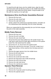
... feed. 4. Gently unlatch the maintenance assembly latches, and slide out the maintenance drive assembly, then the rocker assembly. Remove the print cartridge. 3. Lift the machine from the middle frame. 8. Remove the left side frame onto the middle frame, align the right side frame...cables. 5. Remove the maintenance station. Remove the end-of-forms flag. 13. Disconnect J4, J5, and J6 from the system board. 6. 4076-0XX To install the left side frame. 9. Maintenance Drive And Rocker Assemblies Removal 1. Remove the right side frame. 14. Remove the 3 operator ...
... feed. 4. Gently unlatch the maintenance assembly latches, and slide out the maintenance drive assembly, then the rocker assembly. Remove the print cartridge. 3. Lift the machine from the middle frame. 8. Remove the left side frame onto the middle frame, align the right side frame...cables. 5. Remove the maintenance station. Remove the end-of-forms flag. 13. Disconnect J4, J5, and J6 from the system board. 6. 4076-0XX To install the left side frame. 9. Maintenance Drive And Rocker Assemblies Removal 1. Remove the right side frame. 14. Remove the 3 operator ...
Service Manual
Page 55
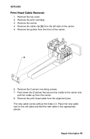
... top cover. 2. Place the new cable next to the carrier and pull the cradle up from the left side of the carrier. Remove the print cartridge. 3. 4076-0XX Print Head Cable Removal 1.
... top cover. 2. Place the new cable next to the carrier and pull the cradle up from the left side of the carrier. Remove the print cartridge. 3. 4076-0XX Print Head Cable Removal 1.
Service Manual
Page 56
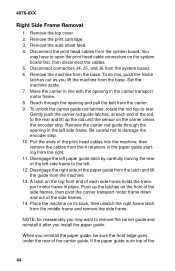
4076-0XX Right Side Frame Removal 1. Reach through the opening in the left paper guide latch by carefully moving the rear of the paper guide from ... front end of the carrier guide. Pull the ends of the 44 NOTE: for reassembly you may have to the left. 12. Remove the print cartridge. 3. Remove the top cover. 2. A latch on top of the print head cables into the machine, then remove the cables from the base. When you reinstall...
4076-0XX Right Side Frame Removal 1. Reach through the opening in the left paper guide latch by carefully moving the rear of the paper guide from ... front end of the carrier guide. Pull the ends of the 44 NOTE: for reassembly you may have to the left. 12. Remove the print cartridge. 3. Remove the top cover. 2. A latch on top of the print head cables into the machine, then remove the cables from the base. When you reinstall...
Service Manual
Page 57
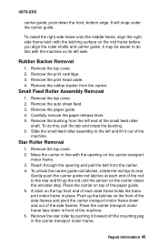
It may be easier to the left end of the small feed roller shaft. Remove the print cartridge. 3. Remove the top cover. 2. Remove the paper guide 4. To do this , pull the tab and rotate the bushing. 6. Move the carrier in line with the ... to do this with the latching surface on top of the paper guide. 5. Place the carrier transport motor frame face down the front, bottom edge. 4076-0XX carrier guide, push down in front of the machine. 6. Carefully remove the paper release lever. 5. Repair Information 45 Remove the top cover. 2. To install...
It may be easier to the left end of the small feed roller shaft. Remove the print cartridge. 3. Remove the top cover. 2. Remove the paper guide 4. To do this , pull the tab and rotate the bushing. 6. Move the carrier in line with the ... to do this with the latching surface on top of the paper guide. 5. Place the carrier transport motor frame face down the front, bottom edge. 4076-0XX carrier guide, push down in front of the machine. 6. Carefully remove the paper release lever. 5. Repair Information 45 Remove the top cover. 2. To install...
Service Manual
Page 58
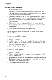
...off the printer. 2. Check the bi-directional alignment. Hold down the Form Feed, Line Feed, and Install Ink Cartridge buttons and turn on the printer. You may have to push the EOF flag out of paper in the manual feed... cable connectors on the printer. Disconnect connectors J4, J5, and J6 from the base. Hold down the Install Print Cartridge, Form Feed and Draft/Letter Quality buttons and turn on the system board first, then disconnect the cables. 3. Turn... from the system board. Disconnect the power supply cable from the system board. 5. 4076-0XX System Board Removal 1.
...off the printer. 2. Check the bi-directional alignment. Hold down the Form Feed, Line Feed, and Install Ink Cartridge buttons and turn on the printer. You may have to push the EOF flag out of paper in the manual feed... cable connectors on the printer. Disconnect connectors J4, J5, and J6 from the base. Hold down the Install Print Cartridge, Form Feed and Draft/Letter Quality buttons and turn on the system board first, then disconnect the cables. 3. Turn... from the system board. Disconnect the power supply cable from the system board. 5. 4076-0XX System Board Removal 1.
Service Manual
Page 59
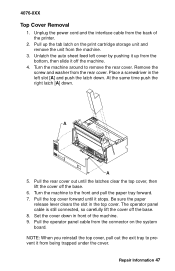
... prevent it from the back of the machine. 9. Pull the rear cover out until it off the machine. 4. Set the cover down . Repair Information 47 4076-0XX Top Cover Removal 1. Pull the top cover forward until the latches clear the top cover, then lift the cover off the base. 8. NOTE: When... operator panel cable is still connected, so carefully lift the cover off the base. 6. Pull the operator panel cable from the connector on the print cartridge storage unit and remove the unit from the rear cover. At the same time push the right latch [A] down in the left cover by pushing...
... prevent it from the back of the machine. 9. Pull the rear cover out until it off the machine. 4. Set the cover down . Repair Information 47 4076-0XX Top Cover Removal 1. Pull the top cover forward until the latches clear the top cover, then lift the cover off the base. 8. NOTE: When... operator panel cable is still connected, so carefully lift the cover off the base. 6. Pull the operator panel cable from the connector on the print cartridge storage unit and remove the unit from the rear cover. At the same time push the right latch [A] down in the left cover by pushing...
Service Manual
Page 65
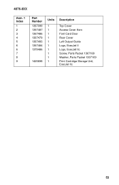
4076-0XX Asm. 1 Index 1 2 3 4 5 6 6 7 8 9 Part Number 1367099 1367487 1367486 1367479 1367493 1367484 1375486 1425698 Units 1 1 1 1 1 1 1 1 1 1 Description Top Cover Access Cover Asm Font Card Door Rear Cover Left Output Guide Logo, ExecJet II Logo, ExecJet IIc Screw, Parts Packet 1367169 Washer, Parts Packet 1367169 Print Cartridge Storage Unit, ExecJet IIc 53
4076-0XX Asm. 1 Index 1 2 3 4 5 6 6 7 8 9 Part Number 1367099 1367487 1367486 1367479 1367493 1367484 1375486 1425698 Units 1 1 1 1 1 1 1 1 1 1 Description Top Cover Access Cover Asm Font Card Door Rear Cover Left Output Guide Logo, ExecJet II Logo, ExecJet IIc Screw, Parts Packet 1367169 Washer, Parts Packet 1367169 Print Cartridge Storage Unit, ExecJet IIc 53


