Service Manual
Page 3
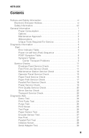
... Transport Problems 9 Service Checks 11 Envelope Feed Service Check 11 First Print Line Service Check 11 Maintenance Station Service Check 12 Operator Panel Service Check 13 Paper Feed Service Check 14 Paper Path Service Check 17 Parallel Port Service Check 18 Power Service Check 19 Print Quality Service Check 20 Simm Service Check 22 Transport Service Check 22 Diagnostic Aids 24 Demo Test 24 Print Fonts Test 24 Purge Test 25 Print Nvram 25 Test Page 26 Paper Sensor Test 26 Encoder Sensor Test 27 Hex Print 27 Parallel Port Test 28 Initialize Nvram 28 Serial Adapter Test...
... Transport Problems 9 Service Checks 11 Envelope Feed Service Check 11 First Print Line Service Check 11 Maintenance Station Service Check 12 Operator Panel Service Check 13 Paper Feed Service Check 14 Paper Path Service Check 17 Parallel Port Service Check 18 Power Service Check 19 Print Quality Service Check 20 Simm Service Check 22 Transport Service Check 22 Diagnostic Aids 24 Demo Test 24 Print Fonts Test 24 Purge Test 25 Print Nvram 25 Test Page 26 Paper Sensor Test 26 Encoder Sensor Test 27 Hex Print 27 Parallel Port Test 28 Initialize Nvram 28 Serial Adapter Test...
Service Manual
Page 4
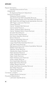
... Maintenance Drive And Rocker Assemblies Removal . . . 40 Middle Frame Removal 40 Operator Panel Removal 40 Outside Idler Gears Removal 41 Paper Ejectors Removal 41 Paper Feed Motor Removal 41 Paper Guide Removal 41 Paper Release Lever Removal 42 Power Supply Removal 42 Print Head Cable Removal 43 Right Side Frame Removal 44 Rubber Backer Removal 45 Small Feed Roller Assembly Removal 45 Star Roller Removal 45 System Board Removal 46 Top Cover Removal 47 Connector Locations 48 System Board Connectors 48 Preventive Maintenance 50 Lubrication Specifications...
... Maintenance Drive And Rocker Assemblies Removal . . . 40 Middle Frame Removal 40 Operator Panel Removal 40 Outside Idler Gears Removal 41 Paper Ejectors Removal 41 Paper Feed Motor Removal 41 Paper Guide Removal 41 Paper Release Lever Removal 42 Power Supply Removal 42 Print Head Cable Removal 43 Right Side Frame Removal 44 Rubber Backer Removal 45 Small Feed Roller Assembly Removal 45 Star Roller Removal 45 System Board Removal 46 Top Cover Removal 47 Connector Locations 48 System Board Connectors 48 Preventive Maintenance 50 Lubrication Specifications...
Service Manual
Page 13
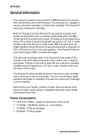
...-to-right with the color print cartridge installed and print speeds are general purpose highquality ink jet printers with a resolution of 300 x 300 pels per inch in text and graphics. The black print cartridge has a total of paper sizes as well as envelopes and other media using three major colors; Printing is used in the ExecJet IIc has a total of 48 nozzles in the print head using an integrated automatic sheet feeder and manual insert tray. Idle Mode (power on -
...-to-right with the color print cartridge installed and print speeds are general purpose highquality ink jet printers with a resolution of 300 x 300 pels per inch in text and graphics. The black print cartridge has a total of paper sizes as well as envelopes and other media using three major colors; Printing is used in the ExecJet IIc has a total of 48 nozzles in the print head using an integrated automatic sheet feeder and manual insert tray. Idle Mode (power on -
Service Manual
Page 15
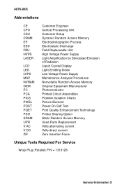
... Unit Customer Setup Dynamic Random Access Memory Electrophotographic Process Electrostatic Discharge Field Replaceable Unit High Voltage Power Supply Light Amplification by Stimulated Emission of Radiation Liquid Crystal Display Light-Emitting Diode Low Voltage Power Supply Maintenance Analysis Procedures Nonvolatile Random Access Memory Original Equipment Manufacturer Photoconductor Printed Circuit Assemblies Problem Isolation Charts Picture Element Power-On Self Test Print Quality Enhancement Technology Printer Sharing Option Static Random Access Memory Used Parts Replacement Volts...
... Unit Customer Setup Dynamic Random Access Memory Electrophotographic Process Electrostatic Discharge Field Replaceable Unit High Voltage Power Supply Light Amplification by Stimulated Emission of Radiation Liquid Crystal Display Light-Emitting Diode Low Voltage Power Supply Maintenance Analysis Procedures Nonvolatile Random Access Memory Original Equipment Manufacturer Photoconductor Printed Circuit Assemblies Problem Isolation Charts Picture Element Power-On Self Test Print Quality Enhancement Technology Printer Sharing Option Static Random Access Memory Used Parts Replacement Volts...
Service Manual
Page 16
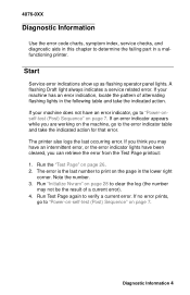
... error. The error is the last number to print on page 7. Diagnostic Information 4 The printer also logs the last occurring error. Run "Initialize Nvram" on page 28 to clear the log (the number may have an intermittent error, or the error indicator lights have an error indicator, go to "Power-onself-test (Post) Sequence" on the page in a malfunctioning printer. 4076-0XX Diagnostic Information 4 Use the error code charts, symptom index, service checks, and...
... error. The error is the last number to print on page 7. Diagnostic Information 4 The printer also logs the last occurring error. Run "Initialize Nvram" on page 28 to clear the log (the number may have an intermittent error, or the error indicator lights have an error indicator, go to "Power-onself-test (Post) Sequence" on the page in a malfunctioning printer. 4076-0XX Diagnostic Information 4 Use the error code charts, symptom index, service checks, and...
Service Manual
Page 20
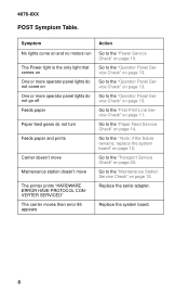
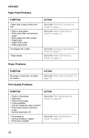
... operator panel lights do not go off Feeds paper Paper feed gears do not turn Go to the "Paper Feed Service Check" on page 13. Go to the "Maintenance Station Service Check" on page 13. Go to the "Operator Panel Service Check" on page 12. Replace the system board. 8 Carrier doesn't move Maintenance station doesn't move The printer prints "HARDWARE ERROR HAVE PROTOCOL CONVERTER SERVICED" The carrier moves then error 85 appears Go to the "Power Service Check" on page 19...
... operator panel lights do not go off Feeds paper Paper feed gears do not turn Go to the "Paper Feed Service Check" on page 13. Go to the "Maintenance Station Service Check" on page 13. Go to the "Operator Panel Service Check" on page 12. Replace the system board. 8 Carrier doesn't move Maintenance station doesn't move The printer prints "HARDWARE ERROR HAVE PROTOCOL CONVERTER SERVICED" The carrier moves then error 85 appears Go to the "Power Service Check" on page 19...
Service Manual
Page 21
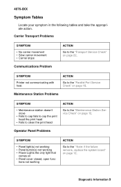
... • Fails to cap fails to cap the print head the print head • Fails to clean the print head ACTION Go to the "Parallel Port Service Check" on page 18. Diagnostic Information 9 SYMPTOM Printer not communicating with host. ACTION Go to the "Maintenance Station Service Check" on page 22. Operator Panel Problems SYMPTOM • Panel light(s) not working • Panel button(s) not working ACTION Go to the "Transport Service Check" on page 12. tions not working • Power Lights the only light that...
... • Fails to cap fails to cap the print head the print head • Fails to clean the print head ACTION Go to the "Parallel Port Service Check" on page 18. Diagnostic Information 9 SYMPTOM Printer not communicating with host. ACTION Go to the "Maintenance Station Service Check" on page 22. Operator Panel Problems SYMPTOM • Panel light(s) not working • Panel button(s) not working ACTION Go to the "Transport Service Check" on page 12. tions not working • Power Lights the only light that...
Service Manual
Page 22
... the "Power Service Check" on page 11. Go to the "Envelope Feed Service Check" on page 19. SYMPTOM No power in characters • Light print • Prints off • Ink smearing • Vertical streaks on paper • Print lines crowded ACTION Go to the "Print Quality Service Check" on page 14. 10 Go to the "Paper Path Service Check" on page 14. Go to the "Paper Feed Service Check" on page 17. Go to the "Paper Feed Service Check" on page 20. 4076-0XX Paper Feed Problems SYMPTOM Paper fails to stop...
... the "Power Service Check" on page 11. Go to the "Envelope Feed Service Check" on page 19. SYMPTOM No power in characters • Light print • Prints off • Ink smearing • Vertical streaks on paper • Print lines crowded ACTION Go to the "Print Quality Service Check" on page 14. 10 Go to the "Paper Path Service Check" on page 14. Go to the "Paper Feed Service Check" on page 17. Go to the "Paper Feed Service Check" on page 20. 4076-0XX Paper Feed Problems SYMPTOM Paper fails to stop...

Service Manual
Page 23
... sensor. Check all parts of -Forms Sensor 3 System Board 4 Feed Arm Assembly 5 Software Setting 6 Operator Panel ACTION Check the flag for dirt. Check the sensor for binds or damage. Use Toolkit, on page 22. 4076-0XX SIMM Problem SYMPTOM Can't write to SIMM ACTION Go to the "Simm Service Check" on the setup diskette, to adjust the Top of Form setting. Service Checks Envelope Feed Service Check FRU OR PROCEDURE 1 Envelope Loading ACTION Be sure the envelope guides have been turned...
... sensor. Check all parts of -Forms Sensor 3 System Board 4 Feed Arm Assembly 5 Software Setting 6 Operator Panel ACTION Check the flag for dirt. Check the sensor for binds or damage. Use Toolkit, on page 22. 4076-0XX SIMM Problem SYMPTOM Can't write to SIMM ACTION Go to the "Simm Service Check" on the setup diskette, to adjust the Top of Form setting. Service Checks Envelope Feed Service Check FRU OR PROCEDURE 1 Envelope Loading ACTION Be sure the envelope guides have been turned...
Service Manual
Page 26
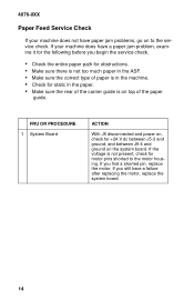
... service check. 4076-0XX Paper Feed Service Check If your machine does have a paper jam problem, examine it for the following before you begin the service check. • Check the entire paper path for obstructions. • Make sure there is not too much paper in the ASF. • Make sure the correct type of paper is in the machine. • Check for static in the paper. • Make sure the rear of the paper guide...
... service check. 4076-0XX Paper Feed Service Check If your machine does have a paper jam problem, examine it for the following before you begin the service check. • Check the entire paper path for obstructions. • Make sure there is not too much paper in the ASF. • Make sure the correct type of paper is in the machine. • Check for static in the paper. • Make sure the rear of the paper guide...
Service Manual
Page 36
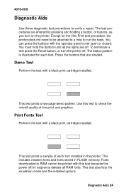
... the tests. To terminate a test press the Reset button, or turn on sequence deletes all the lights are off . The test procedures are shaded. Print Fonts Test Perform this test with a black print cartridge installed. 4076-0XX Diagnostic Aids 4 Use these diagnostic test procedures to RAM cannot be attached to a host to check the overall quality of each test. Fonts downloaded to verify a repair. You can press the buttons with the operator panel cover open or...
... the tests. To terminate a test press the Reset button, or turn on sequence deletes all the lights are off . The test procedures are shaded. Print Fonts Test Perform this test with a black print cartridge installed. 4076-0XX Diagnostic Aids 4 Use these diagnostic test procedures to RAM cannot be attached to a host to check the overall quality of each test. Fonts downloaded to verify a repair. You can press the buttons with the operator panel cover open or...
Service Manual
Page 37
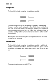
... checks the electronic connection to push the EOF flag out of all the nozzles in the print cartridge. In addition to holding down the buttons, ExecJet IIc requires that you place a piece of paper in the cartridge. 4076-0XX Purge Test Perform this test with a black print cartridge installed. This test prints out a nozzle test pattern followed by several grey lines and another nozzle test pattern. This test prints the contents of NVRAM. Running this test with a color print cartridge installed will clear...
... checks the electronic connection to push the EOF flag out of all the nozzles in the print cartridge. In addition to holding down the buttons, ExecJet IIc requires that you place a piece of paper in the cartridge. 4076-0XX Purge Test Perform this test with a black print cartridge installed. This test prints out a nozzle test pattern followed by several grey lines and another nozzle test pattern. This test prints the contents of NVRAM. Running this test with a color print cartridge installed will clear...
Service Manual
Page 38
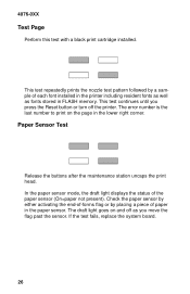
... each font installed in FLASH memory. Paper Sensor Test Release the buttons after the maintenance station uncaps the print head. This test continues until you press the Reset button or turn off as fonts stored in the printer including resident fonts as well as you move the flag past the sensor. 4076-0XX Test Page Perform this test with a black print cartridge installed. This test repeatedly prints the nozzle test pattern followed by placing a piece of the paper sensor (On=paper not...
... each font installed in FLASH memory. Paper Sensor Test Release the buttons after the maintenance station uncaps the print head. This test continues until you press the Reset button or turn off as fonts stored in the printer including resident fonts as well as you move the flag past the sensor. 4076-0XX Test Page Perform this test with a black print cartridge installed. This test repeatedly prints the nozzle test pattern followed by placing a piece of the paper sensor (On=paper not...
Service Manual
Page 39
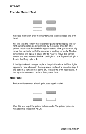
... a black print cartridge installed. Diagnostic Aids 27 4076-0XX Encoder Sensor Test Release the button after the maintenance station uncaps the print head. If the symptom remains, replace the system board. Hex Print Perform this test the bottom three operator panel lights display the current carrier position as you to verify the encoder is working correctly. The printer prints in hex mode. If the lights do not come on, replace the print head cable. If the bottom 3 lights...
... a black print cartridge installed. Diagnostic Aids 27 4076-0XX Encoder Sensor Test Release the button after the maintenance station uncaps the print head. If the symptom remains, replace the system board. Hex Print Perform this test the bottom three operator panel lights display the current carrier position as you to verify the encoder is working correctly. The printer prints in hex mode. If the lights do not come on, replace the print head cable. If the bottom 3 lights...
Service Manual
Page 40
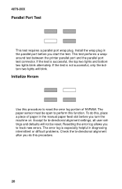
... bottom two lights will not be open to track new errors. To do this function. Except for bi-directional alignment settings, all user settings and defaults will blink. This test performs a wraparound test between the printer parallel port and the parallel port test connector. The paper sensor must be reset. Resetting the error log allows you do this procedure to reset the error log portion of paper in the manual paper feed slot before you turn the machine...
... bottom two lights will not be open to track new errors. To do this function. Except for bi-directional alignment settings, all user settings and defaults will blink. This test performs a wraparound test between the printer parallel port and the parallel port test connector. The paper sensor must be reset. Resetting the error log allows you do this procedure to reset the error log portion of paper in the manual paper feed slot before you turn the machine...

Service Manual
Page 41
To run the test: 1. This test checks out the connection between the serial adapter and the printer. Turn the machine on the serial adapter card to ON. 3. Diagnostic Aids 29 Turn the machine off. 2. Set switch 10 on to print the test. You may have to press Forms Feed to print out the current switch settings and a test pattern. 4. 4076-0XX Serial Adapter Test Perform this test with a black print cartridge installed.
To run the test: 1. This test checks out the connection between the serial adapter and the printer. Turn the machine on the serial adapter card to ON. 3. Diagnostic Aids 29 Turn the machine off. 2. Set switch 10 on to print the test. You may have to press Forms Feed to print out the current switch settings and a test pattern. 4. 4076-0XX Serial Adapter Test Perform this test with a black print cartridge installed.
Service Manual
Page 43
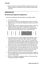
... in NVRAM. Repair Information 31 Hold down the Install Print Cartridge button and the Line Feed Button, then turn off the printer. 2. A page loads and the bi-directional alignment pattern prints. When the alignment is correct, press the Draft button to switch to the right. The bars are aligned when the adjustment is used because low humidity increases static electricity. Each time you press the button the three lines will print. 6. Press the left button to move the...
... in NVRAM. Repair Information 31 Hold down the Install Print Cartridge button and the Line Feed Button, then turn off the printer. 2. A page loads and the bi-directional alignment pattern prints. When the alignment is correct, press the Draft button to switch to the right. The bars are aligned when the adjustment is used because low humidity increases static electricity. Each time you press the button the three lines will print. 6. Press the left button to move the...
Service Manual
Page 56
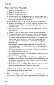
... 4 retainers in the carrier transport motor frame. 8. 4076-0XX Right Side Frame Removal 1. Remove the print cartridge. 3. You may want to damage the encoder strip. 10. Set the machine aside. 7. Be careful not to remove the carrier guide and reinstall it after you install the paper guide. Disconnect the print head cables from the machine. 13. Remove the top cover. 2. Place the machine on top of the...
... 4 retainers in the carrier transport motor frame. 8. 4076-0XX Right Side Frame Removal 1. Remove the print cartridge. 3. You may want to damage the encoder strip. 10. Set the machine aside. 7. Be careful not to remove the carrier guide and reinstall it after you install the paper guide. Disconnect the print head cables from the machine. 13. Remove the top cover. 2. Place the machine on top of the...
Service Manual
Page 58
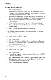
... board. 5. Disconnect the power supply cable from the system board. 4. Hold down the Form Feed, Line Feed, and Install Ink Cartridge buttons and turn on the system board first, then disconnect the cables. 3. Turn off the printer. 2. Check the bi-directional alignment. Check the bi-directional alignment adjustment. You may have to push the EOF flag out of paper in the manual feed slot to open the print head cable connectors on the printer. To do this...
... board. 5. Disconnect the power supply cable from the system board. 4. Hold down the Form Feed, Line Feed, and Install Ink Cartridge buttons and turn on the system board first, then disconnect the cables. 3. Turn off the printer. 2. Check the bi-directional alignment. Check the bi-directional alignment adjustment. You may have to push the EOF flag out of paper in the manual feed slot to open the print head cable connectors on the printer. To do this...
Service Manual
Page 88
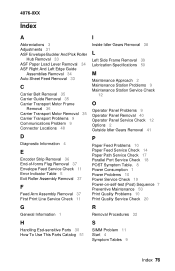
... 38 L Left Side Frame Removal 39 Lubrication Specifications 50 M Maintenance Approach 2 Maintenance Station Problems 9 Maintenance Station Service Check 12 O Operator Panel Problems 9 Operator Panel Removal 40 Operator Panel Service Check 12 Options 2 Outside Idler Gears Removal 41 P Paper Feed Problems 10 Paper Feed Service Check 14 Paper Path Service Check 17 Parallel Port Service Check 18 POST Symptom Table. 8 Power Consumption 1 Power Problems 10 Power Service Check 19 Power-on-self-test (Post) Sequence 7 Preventive Maintenance 50 Print Quality Problems 10 Print Quality Service Check 20...
... 38 L Left Side Frame Removal 39 Lubrication Specifications 50 M Maintenance Approach 2 Maintenance Station Problems 9 Maintenance Station Service Check 12 O Operator Panel Problems 9 Operator Panel Removal 40 Operator Panel Service Check 12 Options 2 Outside Idler Gears Removal 41 P Paper Feed Problems 10 Paper Feed Service Check 14 Paper Path Service Check 17 Parallel Port Service Check 18 POST Symptom Table. 8 Power Consumption 1 Power Problems 10 Power Service Check 19 Power-on-self-test (Post) Sequence 7 Preventive Maintenance 50 Print Quality Problems 10 Print Quality Service Check 20...


