
Service Manual
Page 5
Push Tractor Assembly Removal 4-53 Ribbon Drive Rack Gear Removal 4-54 Right Side Frame Removal 4-56 Right Side Frame Gears Removal 4-58 Sub Logic Board Removal 4-59 Tension Pulley Plate Assembly 4-60 Top ... 5-3 Tractor 2 Cable Connectors 5-4 Wiring Diagrams 5-5 Block Diagram 238X-001 5-5 Block Diagram 239X-001 5-6 Block Diagram 238X-002 5-7 Block Diagram 239X-002 5-8 Block Diagram 238X-003 5-9 Block Diagram 239X-003 5-10 Signal Connections 5-11 Connector Locations 5-20 Main Logic Board 23XX-001 5-20 Main Logic Board 23XX-002 5-21 Main Logic Board 23XX...
Push Tractor Assembly Removal 4-53 Ribbon Drive Rack Gear Removal 4-54 Right Side Frame Removal 4-56 Right Side Frame Gears Removal 4-58 Sub Logic Board Removal 4-59 Tension Pulley Plate Assembly 4-60 Top ... 5-3 Tractor 2 Cable Connectors 5-4 Wiring Diagrams 5-5 Block Diagram 238X-001 5-5 Block Diagram 239X-001 5-6 Block Diagram 238X-002 5-7 Block Diagram 239X-002 5-8 Block Diagram 238X-003 5-9 Block Diagram 239X-003 5-10 Signal Connections 5-11 Connector Locations 5-20 Main Logic Board 23XX-001 5-20 Main Logic Board 23XX-002 5-21 Main Logic Board 23XX...

Service Manual
Page 42
If the bind is getting to -platen gap. • Clean and lubricated carrier shaft. • Idler pulley not binding. • Ribbon drive rack gear teeth not damaged. If the carrier moves manually without binding but the Home Position Error still occurs, verify that the 5 V dc home position sensor ...
If the bind is getting to -platen gap. • Clean and lubricated carrier shaft. • Idler pulley not binding. • Ribbon drive rack gear teeth not damaged. If the carrier moves manually without binding but the Home Position Error still occurs, verify that the 5 V dc home position sensor ...

Service Manual
Page 76
... sure a gap exists between the printhead and the right end of the following parts: • Carrier • Platen • Pinch Roller (Lower) • Ribbon Drive Rack Gear • Side Frame (Left) • Side Frame (Right) • Paper Separator • Feed Roller (Lower) • Paper Guide. Perform the printhead-to-platen gap... WARNING: To prevent damage to the printhead when this adjustment is installed. 4-2 Adjustments CAUTION: Be sure to unplug the power cord whenever you turn the printer on the printer with one of the covers removed.
... sure a gap exists between the printhead and the right end of the following parts: • Carrier • Platen • Pinch Roller (Lower) • Ribbon Drive Rack Gear • Side Frame (Left) • Side Frame (Right) • Paper Separator • Feed Roller (Lower) • Paper Guide. Perform the printhead-to-platen gap... WARNING: To prevent damage to the printhead when this adjustment is installed. 4-2 Adjustments CAUTION: Be sure to unplug the power cord whenever you turn the printer on the printer with one of the covers removed.

Service Manual
Page 92
... Removal" on page 4-42. 4. Remove the carrier see "Lower Pinch Roller Removal" on page 4-12. 11. 23XX-002, 003: Remove the tractor idler gear. 12. 23XX-002, 003: Remove the support plate. 13. Release the latch, and then remove the release slider cam [4] from the right side frame. ... 9. Remove the sub slider cam and the slider cam from the right side frame. 23XX-003 - Remove the tension pulley plate assembly see "Carrier Motor Assembly Removal" on page 4-60. 10. Remove the ribbon drive rack gear see "Paper Guide / Platen Assembly Removal" on page 4-54. 16. Remove the ...
... Removal" on page 4-42. 4. Remove the carrier see "Lower Pinch Roller Removal" on page 4-12. 11. 23XX-002, 003: Remove the tractor idler gear. 12. 23XX-002, 003: Remove the support plate. 13. Release the latch, and then remove the release slider cam [4] from the right side frame. ... 9. Remove the sub slider cam and the slider cam from the right side frame. 23XX-003 - Remove the tension pulley plate assembly see "Carrier Motor Assembly Removal" on page 4-60. 10. Remove the ribbon drive rack gear see "Paper Guide / Platen Assembly Removal" on page 4-54. 16. Remove the ...

Service Manual
Page 122
... • Be sure to avoid getting your finger stuck between the carrier and ribbon drive rack gear while moving the carrier. • Firmly grip the latch for the ribbon cartridge to move the carrier. 3. Turn the printer off. 2. Remove the ribbon access cover. 5. Disconnect the power cord at the... printer. • Let the printhead cool for 15 minutes before touching it from the printhead connector. Release the ...
... • Be sure to avoid getting your finger stuck between the carrier and ribbon drive rack gear while moving the carrier. • Firmly grip the latch for the ribbon cartridge to move the carrier. 3. Turn the printer off. 2. Remove the ribbon access cover. 5. Disconnect the power cord at the... printer. • Let the printhead cool for 15 minutes before touching it from the printhead connector. Release the ...

Service Manual
Page 128
Remove the stop [2], if present. 5. Position the carrier midway between the two rack mounting tabs [1] shown. 4. Move the forms thickness lever to the right. 6. Release the snap [3] and move the rack down to disengage the rack from the ribbon drive gear. 4-54 Remove the top cover see "Top Cover Removal" on the right, and move the rack [4] to position 1. 3. Press the tab on page 4-61. 2. Ribbon Drive Rack Gear Removal 1.
Remove the stop [2], if present. 5. Position the carrier midway between the two rack mounting tabs [1] shown. 4. Move the forms thickness lever to the right. 6. Release the snap [3] and move the rack down to disengage the rack from the ribbon drive gear. 4-54 Remove the top cover see "Top Cover Removal" on the right, and move the rack [4] to position 1. 3. Press the tab on page 4-61. 2. Ribbon Drive Rack Gear Removal 1.

Service Manual
Page 141
Connector Locations This chapter shows the locations of specific parts of the printer. Reference A B C D E F G H I J K L M N O P Q R S T U V W Part Name Form Thickness Lever Paper Select Lever Carrier Motor Paper Feed Motor Parallel Interface Connector Main Logic Board Sub Logic Board Power Supply Tractor Unit Pull Tractor Actuator Ribbon Cartridge Ribbon Drive Rack Gear Pinch Roller, Lower Feed Roller, Lower Printhead Printhead Cables Carrier Tension Pulley Plate Feed Roller, Upper Platen Side Frame, Right Side Frame, Left Carrier Plate Connector Locations 5-1 5.
Connector Locations This chapter shows the locations of specific parts of the printer. Reference A B C D E F G H I J K L M N O P Q R S T U V W Part Name Form Thickness Lever Paper Select Lever Carrier Motor Paper Feed Motor Parallel Interface Connector Main Logic Board Sub Logic Board Power Supply Tractor Unit Pull Tractor Actuator Ribbon Cartridge Ribbon Drive Rack Gear Pinch Roller, Lower Feed Roller, Lower Printhead Printhead Cables Carrier Tension Pulley Plate Feed Roller, Upper Platen Side Frame, Right Side Frame, Left Carrier Plate Connector Locations 5-1 5.
Service Manual
Page 187
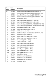
...) Feed Roller (Upper) (2380-002, 003 & 2390-002, 003) Feed Roller (Upper) (2381-002, 003 & 2391-002, 003) Pinch Roller (Lower) (2380 & 2390) Pinch Roller (Lower) (2381 & 2391) Pull Tractor Actuator Kit Side Frame (Right) with Slider Cam (23XX-001, 002) Side Frame (Right) (23XX-003) Ribbon Drive Rack Gear (2380 & 2390) Ribbon Drive Rack Gear (2381 & 2391) Carrier Plate...
...) Feed Roller (Upper) (2380-002, 003 & 2390-002, 003) Feed Roller (Upper) (2381-002, 003 & 2391-002, 003) Pinch Roller (Lower) (2380 & 2390) Pinch Roller (Lower) (2381 & 2391) Pull Tractor Actuator Kit Side Frame (Right) with Slider Cam (23XX-001, 002) Side Frame (Right) (23XX-003) Ribbon Drive Rack Gear (2380 & 2390) Ribbon Drive Rack Gear (2381 & 2391) Carrier Plate...

Service Manual
Page 203
... Print Buffer 4-21 Print Unit 4-47 Printhead 4-48 Printhead Cables 4-49 Pull Tractor Actuator 4-51 Pull Tractor Sensor 4-52 Push Tractor Assembly 4-53 Ribbon Drive Rack Gear 4-54 Right Side Frame 4-56 Side Frame (Right) Gears 4-58 Sub Logic Card 4-59 Tension Pulley Plate 4-60 Top Cover 4-61 Top of Form...
... Print Buffer 4-21 Print Unit 4-47 Printhead 4-48 Printhead Cables 4-49 Pull Tractor Actuator 4-51 Pull Tractor Sensor 4-52 Push Tractor Assembly 4-53 Ribbon Drive Rack Gear 4-54 Right Side Frame 4-56 Side Frame (Right) Gears 4-58 Sub Logic Card 4-59 Tension Pulley Plate 4-60 Top Cover 4-61 Top of Form...