Hardware Maintenance Manual
Page 38
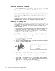
... not turn on , replace the system board. See the following : 1. Power off the computer. 2. If the voltage is correct, replace the system board. 30 ThinkPad X200 and X200s Hardware Maintenance Manual If the resistance is more than 50% of the total power remains; Then reinstall the battery pack. To check your battery, move... room temperature for a moment (but do the following figure: 7(-) 3 4 5 6(-) 2(+) 1(+) Terminal 1 7 Voltage (V dc) + 0 to charge. If the voltage is displayed. The resistance must be able to + 12.6 Ground (-) 3.
... not turn on , replace the system board. See the following : 1. Power off the computer. 2. If the voltage is correct, replace the system board. 30 ThinkPad X200 and X200s Hardware Maintenance Manual If the resistance is more than 50% of the total power remains; Then reinstall the battery pack. To check your battery, move... room temperature for a moment (but do the following figure: 7(-) 3 4 5 6(-) 2(+) 1(+) Terminal 1 7 Voltage (V dc) + 0 to charge. If the voltage is displayed. The resistance must be able to + 12.6 Ground (-) 3.
Hardware Maintenance Manual
Page 56
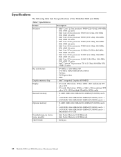
... ThinkPad X200 and X200s Hardware Maintenance Manual Specifications Feature Processor Bus architecture Graphic memory chip Display Standard memory Optional memory Extended memory device (some models) CMOS RAM Description v Intel® Core™ 2 Duo processor P8400 (2.26 GHz), 1066-MHz FSB, 3-MB L2 cache v Intel Core 2 Duo processor P8600 (2.4 GHz), 1066-MHz FSB, 3-MB L2 cache v Intel Core 2 Duo processor P8700 (2.53 GHz...
... ThinkPad X200 and X200s Hardware Maintenance Manual Specifications Feature Processor Bus architecture Graphic memory chip Display Standard memory Optional memory Extended memory device (some models) CMOS RAM Description v Intel® Core™ 2 Duo processor P8400 (2.26 GHz), 1066-MHz FSB, 3-MB L2 cache v Intel Core 2 Duo processor P8600 (2.4 GHz), 1066-MHz FSB, 3-MB L2 cache v Intel Core 2 Duo processor P8700 (2.53 GHz...
Hardware Maintenance Manual
Page 73
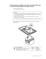
... or SSD and storage converter 1 2 Step 1 Screw (quantity) Hard disk drive screw, M3 × 3 mm, wafer-head, nylon-coated (1) Color Black Torque 0.392 Nm (4 kgfcm) ThinkPad X200 and X200s 65 Table 12. Removal steps of data. The hard disk drive is in suspend mode.
... or SSD and storage converter 1 2 Step 1 Screw (quantity) Hard disk drive screw, M3 × 3 mm, wafer-head, nylon-coated (1) Color Black Torque 0.392 Nm (4 kgfcm) ThinkPad X200 and X200s 65 Table 12. Removal steps of data. The hard disk drive is in suspend mode.
Hardware Maintenance Manual
Page 74
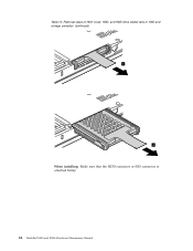
Removal steps of HDD cover, HDD, and HDD drive rubber rails or SSD and storage converter (continued) 3 4 When installing: Make sure that the HDD connector or SSD connector is attached firmly. 66 ThinkPad X200 and X200s Hardware Maintenance Manual Table 12.
Removal steps of HDD cover, HDD, and HDD drive rubber rails or SSD and storage converter (continued) 3 4 When installing: Make sure that the HDD connector or SSD connector is attached firmly. 66 ThinkPad X200 and X200s Hardware Maintenance Manual Table 12.
Hardware Maintenance Manual
Page 75
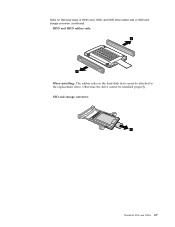
SSD and storage converter: 5 ThinkPad X200 and X200s 67 Table 12. Otherwise the drive cannot be attached to the replacement drive. Removal steps of HDD cover, HDD, and HDD drive rubber rails or SSD and storage converter (continued) HDD and HDD rubber rails: 5 5 When installing: The rubber rails on the hard disk drive must be installed properly.
SSD and storage converter: 5 ThinkPad X200 and X200s 67 Table 12. Otherwise the drive cannot be attached to the replacement drive. Removal steps of HDD cover, HDD, and HDD drive rubber rails or SSD and storage converter (continued) HDD and HDD rubber rails: 5 5 When installing: The rubber rails on the hard disk drive must be installed properly.
Hardware Maintenance Manual
Page 76
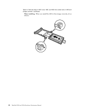
Table 12. Removal steps of HDD cover, HDD, and HDD drive rubber rails or SSD and storage converter (continued) When installing: When you install the SSD in the storage converter, do as follows. 1 68 ThinkPad X200 and X200s Hardware Maintenance Manual
Table 12. Removal steps of HDD cover, HDD, and HDD drive rubber rails or SSD and storage converter (continued) When installing: When you install the SSD in the storage converter, do as follows. 1 68 ThinkPad X200 and X200s Hardware Maintenance Manual
Hardware Maintenance Manual
Page 115
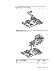
Removal steps of system board, DC-in connector, fan, and ExpressCard slot assembly for ThinkPad X200s (continued) Note: The DC-in connector and the fan assembly are attached to the underside of the system board. 8 9 When installing: Make sure that the DC-in connector and the fan connector are attached to the system board firmly. 10 10 10 11 12 Step 4 Screw (quantity) Color M2 × 3.5 mm, wafer-head, nylon-coated (1) Silver Torque 0.181 Nm (1.85 kgfcm) ThinkPad X200 and X200s 107 Table 27.
Removal steps of system board, DC-in connector, fan, and ExpressCard slot assembly for ThinkPad X200s (continued) Note: The DC-in connector and the fan assembly are attached to the underside of the system board. 8 9 When installing: Make sure that the DC-in connector and the fan connector are attached to the system board firmly. 10 10 10 11 12 Step 4 Screw (quantity) Color M2 × 3.5 mm, wafer-head, nylon-coated (1) Silver Torque 0.181 Nm (1.85 kgfcm) ThinkPad X200 and X200s 107 Table 27.
Hardware Maintenance Manual
Page 118
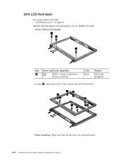
WXGA LCD model: 1 1 1 Step 1 Screw cap Screw (quantity) M2.5 × 4 mm, wafer-head, nylon-coated (3) Color Black Torque 0.392 Nm (4 kgfcm) In step 2 , detach the claws. Then remove the LCD front bezel. 2 2 2 2 2 2 2 2 When installing: Make sure that all the claws are attached firmly. 110 ThinkPad X200 and X200s Hardware Maintenance Manual 2010 LCD front bezel For access, remove this FRU: v "1010 Battery pack" on page 64 Table 28. Removal steps of LCD front bezel for 12.1-in . WXGA LCD model 12.1-in .
WXGA LCD model: 1 1 1 Step 1 Screw cap Screw (quantity) M2.5 × 4 mm, wafer-head, nylon-coated (3) Color Black Torque 0.392 Nm (4 kgfcm) In step 2 , detach the claws. Then remove the LCD front bezel. 2 2 2 2 2 2 2 2 When installing: Make sure that all the claws are attached firmly. 110 ThinkPad X200 and X200s Hardware Maintenance Manual 2010 LCD front bezel For access, remove this FRU: v "1010 Battery pack" on page 64 Table 28. Removal steps of LCD front bezel for 12.1-in . WXGA LCD model 12.1-in .
Hardware Maintenance Manual
Page 119
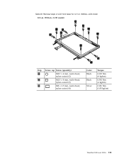
Table 29. WXGA+ LCD model 12.1-in . Removal steps of LCD front bezel for 12.1-in . WXGA+ LCD model: 2 1 3 2 3 2 2 2 1 3 3 Step 1 2 3 Screw cap Screw (quantity) M2.5 × 4 mm, wafer-head, nylon-coated (2) M2.5 × 4 mm, wafer-head, nylon-coated (5) M2 × 3.5 mm, wafer-head, nylon-coated (4) Color Black Black Silver Torque 0.392 Nm (4 kgfcm) 0.392 Nm (4 kgfcm) 0.181 Nm (1.85 kgfcm) ThinkPad X200 and X200s 111
Table 29. WXGA+ LCD model 12.1-in . Removal steps of LCD front bezel for 12.1-in . WXGA+ LCD model: 2 1 3 2 3 2 2 2 1 3 3 Step 1 2 3 Screw cap Screw (quantity) M2.5 × 4 mm, wafer-head, nylon-coated (2) M2.5 × 4 mm, wafer-head, nylon-coated (5) M2 × 3.5 mm, wafer-head, nylon-coated (4) Color Black Black Silver Torque 0.392 Nm (4 kgfcm) 0.392 Nm (4 kgfcm) 0.181 Nm (1.85 kgfcm) ThinkPad X200 and X200s 111
Hardware Maintenance Manual
Page 120
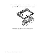
Table 29. Then remove the LCD front bezel. 4 4 4 4 4 4 6 6 5 5 When installing: Make sure that all the claws are attached firmly. 112 ThinkPad X200 and X200s Hardware Maintenance Manual Removal steps of LCD front bezel for 12.1-in. WXGA+ LCD model (continued) In step 4 and 5 , detach the claws.
Table 29. Then remove the LCD front bezel. 4 4 4 4 4 4 6 6 5 5 When installing: Make sure that all the claws are attached firmly. 112 ThinkPad X200 and X200s Hardware Maintenance Manual Removal steps of LCD front bezel for 12.1-in. WXGA+ LCD model (continued) In step 4 and 5 , detach the claws.
Hardware Maintenance Manual
Page 121
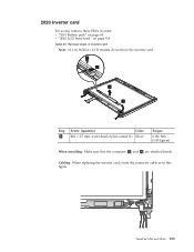
Cabling: When replacing the inverter card, route the connector cable as in . Removal steps of inverter card Note: 12.1-in this figure. ThinkPad X200 and X200s 113 2020 Inverter card For access, remove these FRUs in order: v "1010 Battery pack" on page 64 v "2010 LCD front bezel" on page 110 Table 30. WXGA+ LCD models do not have the inverter card. 1 2 3 4 Step 1 Screw (quantity) Color M2 × 3.5 mm, wafer-head, nylon-coated (1) Silver Torque 0.181 Nm (1.85 kgfcm) When installing: Make sure that the connector 2 and 4 are attached firmly.
Cabling: When replacing the inverter card, route the connector cable as in . Removal steps of inverter card Note: 12.1-in this figure. ThinkPad X200 and X200s 113 2020 Inverter card For access, remove these FRUs in order: v "1010 Battery pack" on page 64 v "2010 LCD front bezel" on page 110 Table 30. WXGA+ LCD models do not have the inverter card. 1 2 3 4 Step 1 Screw (quantity) Color M2 × 3.5 mm, wafer-head, nylon-coated (1) Silver Torque 0.181 Nm (1.85 kgfcm) When installing: Make sure that the connector 2 and 4 are attached firmly.

Hardware Maintenance Manual
Page 124
WXGA LCD model 12.1-in . WXGA LCD model: 2 2 1 2 2 1 Step 1 Screw (quantity) Color M2.5 × 4 mm, wafer-head, nylon-coated (2) Black 2 M2 × 3.5 mm, wafer-head, nylon-coated (4) Silver Torque 0.392 Nm (4 kgfcm) 0.181 Nm (1.85 kgfcm) 116 ThinkPad X200 and X200s Hardware Maintenance Manual Removal steps of LCD panel, LCD brackets, and LCD cable for... palm rest with fingerprint reader" on page 74 v "1070 PCI Express Mini Card for wireless LAN" on page 79 v "1080 PCI Express Mini Card for 12.1-in .
WXGA LCD model 12.1-in . WXGA LCD model: 2 2 1 2 2 1 Step 1 Screw (quantity) Color M2.5 × 4 mm, wafer-head, nylon-coated (2) Black 2 M2 × 3.5 mm, wafer-head, nylon-coated (4) Silver Torque 0.392 Nm (4 kgfcm) 0.181 Nm (1.85 kgfcm) 116 ThinkPad X200 and X200s Hardware Maintenance Manual Removal steps of LCD panel, LCD brackets, and LCD cable for... palm rest with fingerprint reader" on page 74 v "1070 PCI Express Mini Card for wireless LAN" on page 79 v "1080 PCI Express Mini Card for 12.1-in .
Hardware Maintenance Manual
Page 125
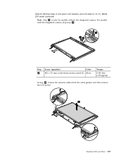
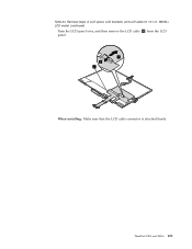
For models with the integrated camera, skip step 3 . 4 33 Step 3 Screw (quantity) Color M2 × 3.5 mm, wafer-head, nylon-coated (2) Silver Torque 0.181 Nm (1.85 kgfcm) In step 5 , release the antenna cables from the cable guides, and then remove the LCD panel. 5 ThinkPad X200 and X200s 117 WXGA LCD model (continued) Note: Step 3 is only for 12.1-in. Table 33. Removal steps of LCD panel, LCD brackets, and LCD cable for models without the integrated camera.
For models with the integrated camera, skip step 3 . 4 33 Step 3 Screw (quantity) Color M2 × 3.5 mm, wafer-head, nylon-coated (2) Silver Torque 0.181 Nm (1.85 kgfcm) In step 5 , release the antenna cables from the cable guides, and then remove the LCD panel. 5 ThinkPad X200 and X200s 117 WXGA LCD model (continued) Note: Step 3 is only for 12.1-in. Table 33. Removal steps of LCD panel, LCD brackets, and LCD cable for models without the integrated camera.
Hardware Maintenance Manual
Page 126
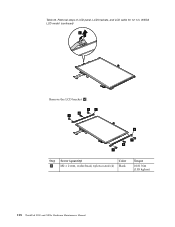
Removal steps of LCD panel, LCD brackets, and LCD cable for 12.1-in. Table 33. WXGA LCD model (continued) 6 Remove the LCD bracket a . 7 a 8 7 a 7 8 7 Step 7 Screw (quantity) M2 × 2 mm, wafer-head, nylon-coated (4) Color Black Torque 0.181 Nm (1.85 kgfcm) 118 ThinkPad X200 and X200s Hardware Maintenance Manual
Removal steps of LCD panel, LCD brackets, and LCD cable for 12.1-in. Table 33. WXGA LCD model (continued) 6 Remove the LCD bracket a . 7 a 8 7 a 7 8 7 Step 7 Screw (quantity) M2 × 2 mm, wafer-head, nylon-coated (4) Color Black Torque 0.181 Nm (1.85 kgfcm) 118 ThinkPad X200 and X200s Hardware Maintenance Manual
Hardware Maintenance Manual
Page 127
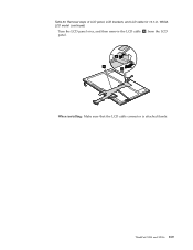
Table 33. WXGA LCD model (continued) Turn the LCD panel over, and then remove the LCD cable b from the LCD panel. 9 b 10 When installing: Make sure that the LCD cable connector is attached firmly. Removal steps of LCD panel, LCD brackets, and LCD cable for 12.1-in. ThinkPad X200 and X200s 119
Table 33. WXGA LCD model (continued) Turn the LCD panel over, and then remove the LCD cable b from the LCD panel. 9 b 10 When installing: Make sure that the LCD cable connector is attached firmly. Removal steps of LCD panel, LCD brackets, and LCD cable for 12.1-in. ThinkPad X200 and X200s 119
Hardware Maintenance Manual
Page 128
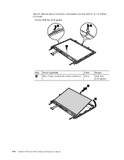
Table 34. WXGA+ LCD model 12.1-in . WXGA+ LCD model: 2 3 1 Step 1 Screw (quantity) M2 x 2 mm, wafer-head, nylon-coated (1) Color Silver Torque 0.181 Nm (1.85 kgfcm) 5 4 120 ThinkPad X200 and X200s Hardware Maintenance Manual Removal steps of LCD panel, LCD brackets, and LCD cable for 12.1-in .
Table 34. WXGA+ LCD model 12.1-in . WXGA+ LCD model: 2 3 1 Step 1 Screw (quantity) M2 x 2 mm, wafer-head, nylon-coated (1) Color Silver Torque 0.181 Nm (1.85 kgfcm) 5 4 120 ThinkPad X200 and X200s Hardware Maintenance Manual Removal steps of LCD panel, LCD brackets, and LCD cable for 12.1-in .
Hardware Maintenance Manual
Page 129
Table 34. WXGA+ LCD model (continued) Turn the LCD panel over, and then remove the LCD cable c from the LCD panel. 7 6 c When installing: Make sure that the LCD cable connector is attached firmly. Removal steps of LCD panel, LCD brackets, and LCD cable for 12.1-in. ThinkPad X200 and X200s 121
Table 34. WXGA+ LCD model (continued) Turn the LCD panel over, and then remove the LCD cable c from the LCD panel. 7 6 c When installing: Make sure that the LCD cable connector is attached firmly. Removal steps of LCD panel, LCD brackets, and LCD cable for 12.1-in. ThinkPad X200 and X200s 121
Hardware Maintenance Manual
Page 130
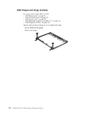
WXGA LCD model: Remove the hinges. 1 1 122 ThinkPad X200 and X200s Hardware Maintenance Manual WXGA LCD model 12.1-in order: v "1010 Battery pack" on page 64 v "2010 LCD front bezel" on page 110 v "2020 Inverter card" on page 113 v "2030 Bluetooth daughter card (BDC-2.1)" on page 114 v "2040 Integrated camera" on page 115 Table 35. 2060 Hinges and hinge brackets For access, remove these FRUs in . Removal steps of hinges for 12.1-in.
WXGA LCD model: Remove the hinges. 1 1 122 ThinkPad X200 and X200s Hardware Maintenance Manual WXGA LCD model 12.1-in order: v "1010 Battery pack" on page 64 v "2010 LCD front bezel" on page 110 v "2020 Inverter card" on page 113 v "2030 Bluetooth daughter card (BDC-2.1)" on page 114 v "2040 Integrated camera" on page 115 Table 35. 2060 Hinges and hinge brackets For access, remove these FRUs in . Removal steps of hinges for 12.1-in.
Hardware Maintenance Manual
Page 131
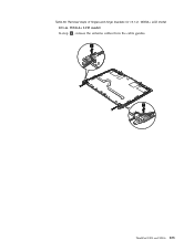
Table 36. Removal steps of hinges and hinge brackets for 12.1-in . WXGA+ LCD model 12.1-in . WXGA+ LCD model: In step 1 , release the antenna cables from the cable guides. 1 1 ThinkPad X200 and X200s 123
Table 36. Removal steps of hinges and hinge brackets for 12.1-in . WXGA+ LCD model 12.1-in . WXGA+ LCD model: In step 1 , release the antenna cables from the cable guides. 1 1 ThinkPad X200 and X200s 123
Hardware Maintenance Manual
Page 132
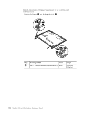
WXGA+ LCD model (continued) Remove the hinges a and the hinge brackets b . 2 3 b a 3 2 b a Step 2 Screw (quantity) Color M2.5 x 4 mm, wafer-head, nylon-coated (2) Black Torque 0.392 Nm (4 kgfcm) 124 ThinkPad X200 and X200s Hardware Maintenance Manual Table 36. Removal steps of hinges and hinge brackets for 12.1-in.
WXGA+ LCD model (continued) Remove the hinges a and the hinge brackets b . 2 3 b a 3 2 b a Step 2 Screw (quantity) Color M2.5 x 4 mm, wafer-head, nylon-coated (2) Black Torque 0.392 Nm (4 kgfcm) 124 ThinkPad X200 and X200s Hardware Maintenance Manual Table 36. Removal steps of hinges and hinge brackets for 12.1-in.


