User Manual
Page 5
...1. General information . . . . 39 The ThinkVantage Productivity Center program . . 39 Additional information resources 39 Specifications 40 Types (6423, 6427, 6483, and 6493 40 Chapter 4. General Checkout . . . . . 41 Problem determination tips 42 Chapter 5. Installing and ...fan assembly 119 Replacing the internal speaker 120 Replacing the front panel connector assembly . . 121 Completing the FRU replacement 123 © Copyright Lenovo 2006, 2008 iii Safety information . . . . . 3 General safety 3 Electrical safety 3 Voltage-selection switch 5 Safety inspection guide...
...1. General information . . . . 39 The ThinkVantage Productivity Center program . . 39 Additional information resources 39 Specifications 40 Types (6423, 6427, 6483, and 6493 40 Chapter 4. General Checkout . . . . . 41 Problem determination tips 42 Chapter 5. Installing and ...fan assembly 119 Replacing the internal speaker 120 Replacing the front panel connector assembly . . 121 Completing the FRU replacement 123 © Copyright Lenovo 2006, 2008 iii Safety information . . . . . 3 General safety 3 Electrical safety 3 Voltage-selection switch 5 Safety inspection guide...
User Manual
Page 6
Chapter 10. FRU lists 159 Machine Type 6423 159 Machine Type 6427 175 Machine Type 6483 192 Machine Type 6493 215 Chapter 12. Notices 239 Television output notice 240 Trademarks 240 iv Hardware Maintenance Manual Additional Service Information 235 Security .../BIOS update failure . . 236 Power management 238 Automatic configuration and power interface (ACPI) BIOS 238 Automatic Power-On features 238 Appendix. Replacing FRUs (types 6427 and 6493 125 Locations 126 Controls and connectors on the front of the computer 126 Connectors on the rear of the computer . . . 127...
Chapter 10. FRU lists 159 Machine Type 6423 159 Machine Type 6427 175 Machine Type 6483 192 Machine Type 6493 215 Chapter 12. Notices 239 Television output notice 240 Trademarks 240 iv Hardware Maintenance Manual Additional Service Information 235 Security .../BIOS update failure . . 236 Power management 238 Automatic configuration and power interface (ACPI) BIOS 238 Automatic Power-On features 238 Appendix. Replacing FRUs (types 6427 and 6493 125 Locations 126 Controls and connectors on the front of the computer 126 Connectors on the rear of the computer . . . 127...

User Manual
Page 46
... in.) Height: 478 mm (18.8 in.) floor to top of handle Depth: 460 mm (18.1 in.) Weight machine types 6423 and 6483: Maximum configuration: 16.33 kg (36 lbs) Dimensions machine types 6427 and 6493: Width: 210 mm (8 in.) Height: 485 mm (19.1 in.) Depth: 579 mm (22.8 in.)...: Operating: 10% to 80% Non-operating: 10% to 90% Transit: 10% to 90% Maximum altitude: 7000 ft (2133.6 m) Electrical input machine types 6423 and 6483 Input voltage: Range 100 V - 240 V Input kilovolt-amperes (kVA) (approximate) Minimum configuration as shipped: 0.17 kVA Maximum configuration: 0.8 kVA Electrical input machine...
... in.) Height: 478 mm (18.8 in.) floor to top of handle Depth: 460 mm (18.1 in.) Weight machine types 6423 and 6483: Maximum configuration: 16.33 kg (36 lbs) Dimensions machine types 6427 and 6493: Width: 210 mm (8 in.) Height: 485 mm (19.1 in.) Depth: 579 mm (22.8 in.)...: Operating: 10% to 80% Non-operating: 10% to 90% Transit: 10% to 90% Maximum altitude: 7000 ft (2133.6 m) Electrical input machine types 6423 and 6483 Input voltage: Range 100 V - 240 V Input kilovolt-amperes (kVA) (approximate) Minimum configuration as shipped: 0.17 kVA Maximum configuration: 0.8 kVA Electrical input machine...

User Manual
Page 95
FRU replacements are documented. © Copyright Lenovo 2006, 2008 89 Only the major FRUs are to be done by trained service technicians only. These precautions and guidelines will help you replace any FRU, read Chapter 2, "Safety information," on page 3. Replacing FRUs (types 6423 and 6483) Important Before you work safely. This chapter does not contain a remove and replace procedure for all FRUs. Chapter 9.
FRU replacements are documented. © Copyright Lenovo 2006, 2008 89 Only the major FRUs are to be done by trained service technicians only. These precautions and guidelines will help you replace any FRU, read Chapter 2, "Safety information," on page 3. Replacing FRUs (types 6423 and 6483) Important Before you work safely. This chapter does not contain a remove and replace procedure for all FRUs. Chapter 9.

User Manual
Page 97
Replacing FRUs (types 6423 and 6483) 91 Connectors on the rear of the computer Some connectors on the rear of your computer are color-coded to help you determine where to ...
Replacing FRUs (types 6423 and 6483) 91 Connectors on the rear of the computer Some connectors on the rear of your computer are color-coded to help you determine where to ...

User Manual
Page 99
... SAS LED connector Auxiliary LEDs connector Front panel connector Cover tamper switch connector Ambient temperature connector Front audio connector Internal speaker Chapter 9. Replacing FRUs (types 6423 and 6483) 93 System board connectors and components 1 COM2 14 2 Battery 15 3 12 volt power connector, 16 graphics 4 Rear fan connector 17 5 Microprocessor heat sink fan...
... SAS LED connector Auxiliary LEDs connector Front panel connector Cover tamper switch connector Ambient temperature connector Front audio connector Internal speaker Chapter 9. Replacing FRUs (types 6423 and 6483) 93 System board connectors and components 1 COM2 14 2 Battery 15 3 12 volt power connector, 16 graphics 4 Rear fan connector 17 5 Microprocessor heat sink fan...

User Manual
Page 101
Replacing FRUs (types 6423 and 6483) 95 See "Opening the cover" on a flat surface. 4. Disengage the bezel latches 1 , one at a time while rotating the bezel away from the computer just enough to replace the front bezel. Lay the front bezel on page 94. 2. Removing the front bezel To remove the front bezel: 1. Reverse these steps to keep the latches disengaged. 3. Chapter 9. Open the cover.
Replacing FRUs (types 6423 and 6483) 95 See "Opening the cover" on a flat surface. 4. Disengage the bezel latches 1 , one at a time while rotating the bezel away from the computer just enough to replace the front bezel. Lay the front bezel on page 94. 2. Removing the front bezel To remove the front bezel: 1. Reverse these steps to keep the latches disengaged. 3. Chapter 9. Open the cover.

User Manual
Page 103
Replacing FRUs (types 6423 and 6483) 97 Chapter 9.
Replacing FRUs (types 6423 and 6483) 97 Chapter 9.

User Manual
Page 105
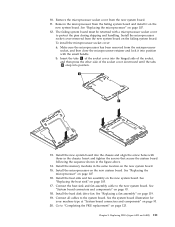
Open the computer cover. Locate the power-supply assembly. See "Internal components" on page 94. 2. Remove the power-supply cables from all adapter cards (some models) and from the cable clips and ties. 5. See "Opening the cover" on page 92. 3. Disconnect the power-supply cables 1 , 2 , and 3 from the system-board connectors, all drives. 4. Remove the four screws at the rear of the chassis that secure the power supply. Replacing FRUs (types 6423 and 6483) 99 Replacing the power supply assembly To replace the power-supply assembly: 1. Chapter 9.
Open the computer cover. Locate the power-supply assembly. See "Internal components" on page 94. 2. Remove the power-supply cables from all adapter cards (some models) and from the cable clips and ties. 5. See "Opening the cover" on page 92. 3. Disconnect the power-supply cables 1 , 2 , and 3 from the system-board connectors, all drives. 4. Remove the four screws at the rear of the chassis that secure the power supply. Replacing FRUs (types 6423 and 6483) 99 Replacing the power supply assembly To replace the power-supply assembly: 1. Chapter 9.

User Manual
Page 107
Depress the power supply latch 1 . Install and tighten the four screws at the rear of the computer, remove it from the chassis. 7. Install the new power-supply assembly into the chassis so that the screw holes in the power-supply assembly align with those in the chassis. Slide the power-supply assembly toward the front of the chassis to secure the power-supply assembly. Note: Use only the screws provided by Lenovo. 8. Replacing FRUs (types 6423 and 6483) 101 Chapter 9. 6.
Depress the power supply latch 1 . Install and tighten the four screws at the rear of the computer, remove it from the chassis. 7. Install the new power-supply assembly into the chassis so that the screw holes in the power-supply assembly align with those in the chassis. Slide the power-supply assembly toward the front of the chassis to secure the power-supply assembly. Note: Use only the screws provided by Lenovo. 8. Replacing FRUs (types 6423 and 6483) 101 Chapter 9. 6.

User Manual
Page 109
.... Disconnect all cable connections on page 93. 6. Push the retention feature toward the front of all cables connected to the adapter card. Replacing FRUs (types 6423 and 6483) 103 Replacing an adapter card 1. Take note of the location of the chassis before removing the adapter card. Some models have: v A screw installed in...
.... Disconnect all cable connections on page 93. 6. Push the retention feature toward the front of all cables connected to the adapter card. Replacing FRUs (types 6423 and 6483) 103 Replacing an adapter card 1. Take note of the location of the chassis before removing the adapter card. Some models have: v A screw installed in...

User Manual
Page 111
... 3 , and fully remove screw 1 . Notes: a. Do not remove the plastic cover until you are ready to replace and install the heat sink. Replacing FRUs (types 6423 and 6483) 105 Remove the heat sink and fan assembly cable from the system board: a. To replace the heat sink: 1. See "Opening the cover" on the...
... 3 , and fully remove screw 1 . Notes: a. Do not remove the plastic cover until you are ready to replace and install the heat sink. Replacing FRUs (types 6423 and 6483) 105 Remove the heat sink and fan assembly cable from the system board: a. To replace the heat sink: 1. See "Opening the cover" on the...

User Manual
Page 113
... to let the computer cool before opening the computer cover. Important Touch only the sides of the socket. To replace the microprocessor: 1. Replacing FRUs (types 6423 and 6483) 107 Turn off the computer and wait three to five minutes to replace the microprocessor. See "Replacing the heat sink" on the bottom. 5. Place...
... to let the computer cool before opening the computer cover. Important Touch only the sides of the socket. To replace the microprocessor: 1. Replacing FRUs (types 6423 and 6483) 107 Turn off the computer and wait three to five minutes to replace the microprocessor. See "Replacing the heat sink" on the bottom. 5. Place...

User Manual
Page 115
Lower the microprocessor straight down into position and replace the 4 screws to secure the heat sink to "Completing the FRU replacement" on page 123. Reconnect the heat sink fan cable. 11. Replacing FRUs (types 6423 and 6483) 109 Go to the system board. 10. 7. Place the heat sink into the microprocessor socket of the system board. 8. Close the microprocessor retainer and clamp it with the small handle. 9. Chapter 9.
Lower the microprocessor straight down into position and replace the 4 screws to secure the heat sink to "Completing the FRU replacement" on page 123. Reconnect the heat sink fan cable. 11. Replacing FRUs (types 6423 and 6483) 109 Go to the system board. 10. 7. Place the heat sink into the microprocessor socket of the system board. 8. Close the microprocessor retainer and clamp it with the small handle. 9. Chapter 9.
User Manual
Page 117
...the heat sink and fan assembly cable to protect the pins during shipping and handling. Install the hard disk drive fan. Replacing FRUs (types 6423 and 6483) 111 Remove the microprocessor from the new system board. 11. See "Replacing the heat sink" on page 107 16. Remove the ..."Completing the FRU replacement" on page 93. 18. b. To install the microprocessor socket cover: a. See the system board illustration for your machine type at "System board connectors and components" on page 107. 12. 10. Install the memory modules in the same location on the new system board....
...the heat sink and fan assembly cable to protect the pins during shipping and handling. Install the hard disk drive fan. Replacing FRUs (types 6423 and 6483) 111 Remove the microprocessor from the new system board. 11. See "Replacing the heat sink" on page 107 16. Remove the ..."Completing the FRU replacement" on page 93. 18. b. To install the microprocessor socket cover: a. See the system board illustration for your machine type at "System board connectors and components" on page 107. 12. 10. Install the memory modules in the same location on the new system board....

User Manual
Page 119
Install the new drive into the drive bay. 7. Install the hard disk drive and bracket into the bracket, flex the bracket, and align the pins 1 through 4 on page 123. Chapter 9. Go to the rear of the hard disk drive. 6. Replacing FRUs (types 6423 and 6483) 113 5. Connect the signal and power cables to "Completing the FRU replacement" on the bracket with the holes in the hard disk drive. Do not touch the circuit board 5 on the bottom of the new hard disk drive. 8.
Install the new drive into the drive bay. 7. Install the hard disk drive and bracket into the bracket, flex the bracket, and align the pins 1 through 4 on page 123. Chapter 9. Go to the rear of the hard disk drive. 6. Replacing FRUs (types 6423 and 6483) 113 5. Connect the signal and power cables to "Completing the FRU replacement" on the bracket with the holes in the hard disk drive. Do not touch the circuit board 5 on the bottom of the new hard disk drive. 8.

User Manual
Page 121
... drive cables from the chassis. See "Removing the front bezel" on page 93. 3. See "System board connectors and components" on page 95. 5. Replacing FRUs (types 6423 and 6483) 115 Replacing the diskette drive or optional card reader This section provides instructions on page 94. 2. See "Opening the cover" on how to replace...
... drive cables from the chassis. See "Removing the front bezel" on page 93. 3. See "System board connectors and components" on page 95. 5. Replacing FRUs (types 6423 and 6483) 115 Replacing the diskette drive or optional card reader This section provides instructions on page 94. 2. See "Opening the cover" on how to replace...

User Manual
Page 123
Chapter 9. Replacing FRUs (types 6423 and 6483) 117 See "Opening the cover" on how to replace a memory module. 1. Remove the memory module being replaced by opening the retaining clips. Replacing a memory module This section provides instructions on page 94. 2. Open the computer cover. Locate the memory-module connectors 1 and 2 . 3.
Chapter 9. Replacing FRUs (types 6423 and 6483) 117 See "Opening the cover" on how to replace a memory module. 1. Remove the memory module being replaced by opening the retaining clips. Replacing a memory module This section provides instructions on page 94. 2. Open the computer cover. Locate the memory-module connectors 1 and 2 . 3.

User Manual
Page 125
... "System board connectors and components" on page 92. 1. See "Internal components" on page 93. See "Removing the front bezel" on page 93. 8. Replacing FRUs (types 6423 and 6483) 119 Disconnect the fan-assembly-wiring connector from the system board. 4. Open the computer cover. If you are replacing the front fan, remove the...
... "System board connectors and components" on page 92. 1. See "Internal components" on page 93. See "Removing the front bezel" on page 93. 8. Replacing FRUs (types 6423 and 6483) 119 Disconnect the fan-assembly-wiring connector from the system board. 4. Open the computer cover. If you are replacing the front fan, remove the...
User Manual
Page 198
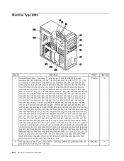
... 2 Duo E6550 - 2.33GHz, 2MBx2 L2, 1333MHz FSB, G0 (models CTO 51A 51Q 51T 51K 51R) FRU# 71Y4884 43C3833 CRU Tier N N 192 Hardware Maintenance Manual Machine Type 6483 Item # 6483 FRUs 1 System Board, Islay -
... 2 Duo E6550 - 2.33GHz, 2MBx2 L2, 1333MHz FSB, G0 (models CTO 51A 51Q 51T 51K 51R) FRU# 71Y4884 43C3833 CRU Tier N N 192 Hardware Maintenance Manual Machine Type 6483 Item # 6483 FRUs 1 System Board, Islay -


