User Manual
Page 5
... 110 Replacing a hard disk drive 112 Replacing an optical drive 114 Replacing the diskette drive or optional card reader 115 Replacing a memory module 117 Replacing a fan assembly 119 Replacing the internal speaker 120 Replacing the front panel connector assembly . . 121 Completing the... FRU replacement 123 © Copyright Lenovo 2006, 2008 iii General Checkout . . . . . 41 Problem determination tips 42 Chapter 5. Using the Setup Utility . . . 49 Starting...
... 110 Replacing a hard disk drive 112 Replacing an optical drive 114 Replacing the diskette drive or optional card reader 115 Replacing a memory module 117 Replacing a fan assembly 119 Replacing the internal speaker 120 Replacing the front panel connector assembly . . 121 Completing the... FRU replacement 123 © Copyright Lenovo 2006, 2008 iii General Checkout . . . . . 41 Problem determination tips 42 Chapter 5. Using the Setup Utility . . . 49 Starting...
User Manual
Page 6
... Replacing the system board 145 Replacing a hard disk drive 148 Replacing an optical drive 150 Replacing the diskette drive or optional card reader 151 Replacing a memory module 153 Replacing a fan assembly 156 Replacing the internal speaker 157 Completing the FRU replacement 158 Chapter 11. Additional Service Information 235 Security features 235...
... Replacing the system board 145 Replacing a hard disk drive 148 Replacing an optical drive 150 Replacing the diskette drive or optional card reader 151 Replacing a memory module 153 Replacing a fan assembly 156 Replacing the internal speaker 157 Completing the FRU replacement 158 Chapter 11. Additional Service Information 235 Security features 235...

User Manual
Page 67
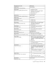
... for information about the Diagnostic programs. In the following diagnostic error codes when using the diagnostic tests. See "Flash update procedures" on page 235 2. Run memory test 4. See "Flash update procedures" on page 235 2. System board 1. Flash the system. See "Flash update procedures" on page 235 3. See "Flash update procedures" on...
... for information about the Diagnostic programs. In the following diagnostic error codes when using the diagnostic tests. See "Flash update procedures" on page 235 2. Run memory test 4. See "Flash update procedures" on page 235 2. System board 1. Flash the system. See "Flash update procedures" on page 235 3. See "Flash update procedures" on...
User Manual
Page 69
... to -FRU Index 63 Adapter card 2. See Chapter 6, "Using the Setup Utility," on page 235 3. Symptom-to "Undetermined problems" on system and re-test 2. Run memory test 4. System board 1. Re-start the test, if necessary 1. Flash the system and retest. System board Information only Re-start the test to reset the...
... to -FRU Index 63 Adapter card 2. See Chapter 6, "Using the Setup Utility," on page 235 3. Symptom-to "Undetermined problems" on system and re-test 2. Run memory test 4. System board 1. Re-start the test, if necessary 1. Flash the system and retest. System board Information only Re-start the test to reset the...
User Manual
Page 75
... 69 Make sure the component that is called out in warning statement 4. Replace the component under function test 1. Flash the system and re-test. Run memory test 4. System board Chapter 8. Symptom-to reset the log file 1. If a component is called out is connected and/or enabled 2. Go to "Undetermined problems" on...
... 69 Make sure the component that is called out in warning statement 4. Replace the component under function test 1. Flash the system and re-test. Run memory test 4. System board Chapter 8. Symptom-to reset the log file 1. If a component is called out is connected and/or enabled 2. Go to "Undetermined problems" on...
User Manual
Page 85
... System board 3. Symptom-to "Undetermined problems" on page 86 1. If a component is called out by the test 2. Check Power supply voltages 3. Replace the memory module called out, make sure it is connected and/or enabled 2. Cache, if removable 2. Diskette drive 4. Re-run test 3. C2 Cover Switch 3. Replace ... Security Test Passed 185-XXX-XXX Asset Security failure 185-278-XXX Asset Security Chassis Intrusion 201-000-XXX System Memory Test Passed 201-XXX-XXX System Memory error 202-000-XXX System Cache Test Passed 202-XXX-XXX System Cache error 206-000-XXX Diskette Drive Test...
... System board 3. Symptom-to "Undetermined problems" on page 86 1. If a component is called out by the test 2. Check Power supply voltages 3. Replace the memory module called out, make sure it is connected and/or enabled 2. Cache, if removable 2. Diskette drive 4. Re-run test 3. C2 Cover Switch 3. Replace ... Security Test Passed 185-XXX-XXX Asset Security failure 185-278-XXX Asset Security Chassis Intrusion 201-000-XXX System Memory Test Passed 201-XXX-XXX System Memory error 202-000-XXX System Cache Test Passed 202-XXX-XXX System Cache error 206-000-XXX Diskette Drive Test...
User Manual
Page 88
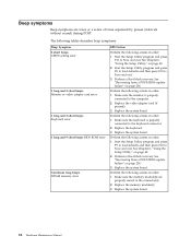
...the keyboard is properly connected to the computer. 2. Replace the keyboard. 3. Perform the following actions in order. 1. Make sure the memory module(s) are tones or a series of tones separated by pauses (intervals without sound) during POST. Start the Setup Utility program and... Utility," on page 49. 2. Replace the video adapter card (if present). 3. Replace the system board. 82 Hardware Maintenance Manual Replace the memory module(s). 3. Replace the system board. Perform a Boot block recovery. Perform the following actions in order. 1. Replace the system board. Perform ...
...the keyboard is properly connected to the computer. 2. Replace the keyboard. 3. Perform the following actions in order. 1. Make sure the memory module(s) are tones or a series of tones separated by pauses (intervals without sound) during POST. Start the Setup Utility program and... Utility," on page 49. 2. Replace the video adapter card (if present). 3. Replace the system board. 82 Hardware Maintenance Manual Replace the memory module(s). 3. Replace the system board. Perform a Boot block recovery. Perform the following actions in order. 1. Replace the system board. Perform ...
User Manual
Page 89
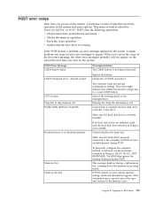
...operations. A single problem can cause several error messages to NONE. CPU at nnnn Press Esc to HALT ON ALL, BUT KEYBOARD. Memory Test: Memory test fail To purposely configure the computer without a keyboard, set to appear. Symptom-to the computer and that CMOS has become ... information gives specifics about the type and location of the microprocessor. defaults loaded Replace the battery. Pressing Esc skips the full memory test Cannot find or initialize the hard disk drive controller or the drive. Cannot initialize the keyboard. This error might indicate ...
...operations. A single problem can cause several error messages to NONE. CPU at nnnn Press Esc to HALT ON ALL, BUT KEYBOARD. Memory Test: Memory test fail To purposely configure the computer without a keyboard, set to appear. Symptom-to the computer and that CMOS has become ... information gives specifics about the type and location of the microprocessor. defaults loaded Replace the battery. Pressing Esc skips the full memory test Cannot find or initialize the hard disk drive controller or the drive. Cannot initialize the keyboard. This error might indicate ...
User Manual
Page 91
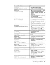
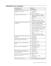
... Board 1. Diskette Drive Cable 1. Network Adapter 1. System Board 1. See "Power Supply Errors" on page 59. Incorrect memory size during POST ″Insert a Diskette″ icon appears with an otherwise blank display. Check power supply and signal cable... adapter (advise network administrator of new MAC address) 1. Diskette Drive 2. System Board 1. Ensure that network adapter is active. Run the Memory tests 2. Diskette Drive Cable 3. Display 2. System Board 2. System Board 3. Video adapter (if present) 3. See "Power Supply Errors"...
... Board 1. Diskette Drive Cable 1. Network Adapter 1. System Board 1. See "Power Supply Errors" on page 59. Incorrect memory size during POST ″Insert a Diskette″ icon appears with an otherwise blank display. Check power supply and signal cable... adapter (advise network administrator of new MAC address) 1. Diskette Drive 2. System Board 1. Ensure that network adapter is active. Run the Memory tests 2. Diskette Drive Cable 3. Display 2. System Board 2. System Board 3. Video adapter (if present) 3. See "Power Supply Errors"...
User Manual
Page 92
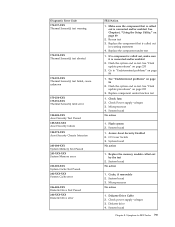
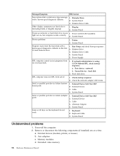
... startup sequence 2. System Board Serial or parallel port device failure (adapter port) 1. External Device 3. Keyboard Cable 3. a. Extended video memory 86 Hardware Maintenance Manual System Board Printer problems 1. Run Setup and check Startup sequence. 2. System Board 5. If network administrator is using... works correctly 2. Diskette Drive 3. hard disk 2. Remove or disconnect the following components (if installed) one at a time. Memory modules d. Hard disk drive RPL computer does not RPL from the hard disk with a known-good diagnostic diskette. 1. Keyboard ...
... startup sequence 2. System Board Serial or parallel port device failure (adapter port) 1. External Device 3. Keyboard Cable 3. a. Extended video memory 86 Hardware Maintenance Manual System Board Printer problems 1. Run Setup and check Startup sequence. 2. System Board 5. If network administrator is using... works correctly 2. Diskette Drive 3. hard disk 2. Remove or disconnect the following components (if installed) one at a time. Memory modules d. Hard disk drive RPL computer does not RPL from the hard disk with a known-good diagnostic diskette. 1. Keyboard ...
User Manual
Page 98
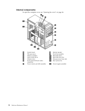
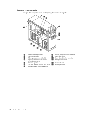
Internal components To open the computer cover, see "Opening the cover" on page 94. 1 System board 8 Internal speaker 2 Microprocessor 9 Front fan assembly 3 Memory modules 10 Hard disk drive 4 Optical disk drives 11 Hard disk drive fan 5 Diskette drive 12 Microprocessor heat sink 6 Front panel USB and Audio 13 Rear system fan connectors 7 Power switch and LED assembly 14 Power-supply assembly 92 Hardware Maintenance Manual
Internal components To open the computer cover, see "Opening the cover" on page 94. 1 System board 8 Internal speaker 2 Microprocessor 9 Front fan assembly 3 Memory modules 10 Hard disk drive 4 Optical disk drives 11 Hard disk drive fan 5 Diskette drive 12 Microprocessor heat sink 6 Front panel USB and Audio 13 Rear system fan connectors 7 Power switch and LED assembly 14 Power-supply assembly 92 Hardware Maintenance Manual

User Manual
Page 99
... volt power connector, 16 graphics 4 Rear fan connector 17 5 Microprocessor heat sink fan 18 connector 6 Microprocessor 12 V power 19 connector 7 Microprocessor and heat sink 20 8 Memory slots (4) 21 9 Front hard disk drive fan 22 connector 10 24-
... volt power connector, 16 graphics 4 Rear fan connector 17 5 Microprocessor heat sink fan 18 connector 6 Microprocessor 12 V power 19 connector 7 Microprocessor and heat sink 20 8 Memory slots (4) 21 9 Front hard disk drive fan 22 connector 10 24-

User Manual
Page 104
... lost. Refer to "Completing the FRU replacement" on page 96. 4. See "System board connectors and components" on page 7 for information about replacing and disposing of memory that maintains the date, time, and settings for the first time after replacing the battery. 7. Note: When the computer is turned on page 94. 3. Replacing...
... lost. Refer to "Completing the FRU replacement" on page 96. 4. See "System board connectors and components" on page 7 for information about replacing and disposing of memory that maintains the date, time, and settings for the first time after replacing the battery. 7. Note: When the computer is turned on page 94. 3. Replacing...
User Manual
Page 116
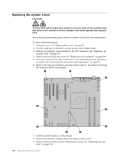
... the chassis, following the sequence shown in the PCI connectors. Remove the hard disk drive fan. See "Replacing a fan assembly" on page 94. 2. Remove the memory modules from the failing system board. Replacing the system board CAUTION: The heat sink and microprocessor might be very hot. See "System board connectors and...
... the chassis, following the sequence shown in the PCI connectors. Remove the hard disk drive fan. See "Replacing a fan assembly" on page 94. 2. Remove the memory modules from the failing system board. Replacing the system board CAUTION: The heat sink and microprocessor might be very hot. See "System board connectors and...
User Manual
Page 117
..." on the new system board. See "System board connectors and components" on page 107. 12. See "Replacing the microprocessor" on page 93. 18. Install the memory modules in the same location on page 93. 20. See the system board illustration for your machine type at "System board connectors and components" on...
..." on the new system board. See "System board connectors and components" on page 107. 12. See "Replacing the microprocessor" on page 93. 18. Install the memory modules in the same location on page 93. 20. See the system board illustration for your machine type at "System board connectors and components" on...

User Manual
Page 123
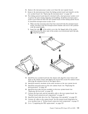
Replacing FRUs (types 6423 and 6483) 117 Replacing a memory module This section provides instructions on page 94. 2. See "Opening the cover" on how to replace a memory module. 1. Chapter 9. Remove the memory module being replaced by opening the retaining clips. Locate the memory-module connectors 1 and 2 . 3. Open the computer cover.
Replacing FRUs (types 6423 and 6483) 117 Replacing a memory module This section provides instructions on page 94. 2. See "Opening the cover" on how to replace a memory module. 1. Chapter 9. Remove the memory module being replaced by opening the retaining clips. Locate the memory-module connectors 1 and 2 . 3. Open the computer cover.

User Manual
Page 124
Make sure the notch 1 on the memory module aligns correctly with the connector key 2 on page 123. 118 Hardware Maintenance Manual Go to "Completing the FRU replacement" on the system board. Position the replacement memory module over the memory slot. 4. Push the memory module straight down into the connector until the retaining clips close. 5.
Make sure the notch 1 on the memory module aligns correctly with the connector key 2 on page 123. 118 Hardware Maintenance Manual Go to "Completing the FRU replacement" on the system board. Position the replacement memory module over the memory slot. 4. Push the memory module straight down into the connector until the retaining clips close. 5.
User Manual
Page 134
Internal components To open the computer cover, see "Opening the cover" on page 94. 1 Power-supply assembly 8 Power switch and LED assembly 2 Memory modules 9 Hard disk drive 3 Microprocessor heat sinks (2) 10 Hard disk drive fan assembly 4 Optical drives (such as a CD or 11 Microprocessors (2) DVD drive) 3 bays 5 Internal speaker 12 System board 6 3.5 inch diskette drive or card reader 13 Rear system fan 7 Front USB and audio connectors 128 Hardware Maintenance Manual
Internal components To open the computer cover, see "Opening the cover" on page 94. 1 Power-supply assembly 8 Power switch and LED assembly 2 Memory modules 9 Hard disk drive 3 Microprocessor heat sinks (2) 10 Hard disk drive fan assembly 4 Optical drives (such as a CD or 11 Microprocessors (2) DVD drive) 3 bays 5 Internal speaker 12 System board 6 3.5 inch diskette drive or card reader 13 Rear system fan 7 Front USB and audio connectors 128 Hardware Maintenance Manual

User Manual
Page 135
System board connectors and components 1 Memory slots (8) 13 Auxiliary USB connector 2 2 24 Pin power connector 14 IEEE 1394 Connector 3 10 Pin power connector 15 Front-panel connector 4 Rear exhaust fan connector ...
System board connectors and components 1 Memory slots (8) 13 Auxiliary USB connector 2 2 24 Pin power connector 14 IEEE 1394 Connector 3 10 Pin power connector 15 Front-panel connector 4 Rear exhaust fan connector ...

User Manual
Page 141
... the electrical outlet and from the computer. 2. Chapter 10. Go to "Safety notices (multi-lingual translations)" on page 7 for information about replacing and disposing of memory that maintains the date, time, and settings for the first time after replacing the battery. 7. An error message is displayed when you turn on for...
... the electrical outlet and from the computer. 2. Chapter 10. Go to "Safety notices (multi-lingual translations)" on page 7 for information about replacing and disposing of memory that maintains the date, time, and settings for the first time after replacing the battery. 7. An error message is displayed when you turn on for...


