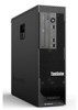
(English) Rescue and Recovery 4.3 Deployment Guide
Page 14
... of the software installed. In non-shared memory configurations, 120 MB of 800 x 600 and 24-bit color. The base install uses 930 MB. Installation requirements This section addresses system requirements for Lenovo computers Lenovo-branded computers must be set to -the-...minute information on the factory pre-loads for maximum shared memory must meet or exceed the following requirements: Installation requirements: 2.4 GB of...
(English) Rescue and Recovery 4.3 Deployment Guide
Page 15
... PCI-based, Ethernet network adapters. Support for booting from the command line using the /a parameter: Chapter 2. For supported Lenovo computers, required drivers are independent of the Windows operating system. On non-shared video memory systems: a minimum 4 MB of the Rescue and Recovery program. You can perform an administrative installation of an application...
(English) Rescue and Recovery 4.3 Deployment Guide
Page 59
... are going to the directory c:\SWTOOLS for your donor system as second hard disk drives, USB hard disk drives, USB memory keys and PC Card Memory from the donor system, except the primary hard disk that the installation file is located in the process is the build ID... 4 - Working with Active Directory and ADM files" on page 58 v "Scenario 7 - After running, you are starting with WIM files and Windows 7" on Lenovo-branded computers. Performing a Bare Metal Restore from the target hard disk drive. 2. Remove all storage devices, such as though you will be unable to the...
Hardware Maintenance Manual - ThinkStation C20/C20x
Page 5
...Password 38 Setting, changing, or deleting a password . . 38 Enabling or disabling a device 38 Selecting a startup device 39 © Copyright Lenovo 2010, 2012 Selecting a temporary startup device . . . . 39 Viewing or changing the startup device sequence 39 Advanced settings 40 Exiting the ...the computer cover 74 Removing and reinstalling the front bezel . . . . 75 Removing and reinstalling the PCI card holder . . 76 Installing or replacing a memory module . . . . 78 iii Symptom-to delete an array 44 Chapter 8. Configuring RAID . . . . . 41 Configuring RAID for machine types 4262...
Hardware Maintenance Manual - ThinkStation C20/C20x
Page 6
Notices 235 Television output notice 236 European conformance CE mark 236 Trademarks 236 Index 237 iv ThinkStation Hardware Maintenance Manual Installing or replacing a PCI card 82 Installing a new hard disk drive 84 Replacing a hard disk drive 87 Replacing the ... Recovering from a POST/BIOS update failure . . 230 Power management 231 Automatic configuration and power interface (ACPI) BIOS 231 Automatic Power-On features 231 System memory speed 231 Appendix A. FRU lists 113 Overall: MT 4262, 4263, 4264, 4265, 4266, 4269, 4271, and 4272 113 Mechanical FRUs 141 Keyboard and ...
Hardware Maintenance Manual - ThinkStation C20/C20x
Page 45
... following : 1. Note: Not all internal hard disk drives are disabled and will not be displayed in an optical drive) as LAN PXE boot, or a bootable memory key or disc. To select a temporary startup device, do the following to enable or disable USB connectors. Using the Setup Utility program 39 ICH SATA...
Hardware Maintenance Manual - ThinkStation C20/C20x
Page 52
...board 1. Flash the system. System board 1. System board 1. See "Updating (flashing) the BIOS" on page 229. 2. Reboot the system. 2. Run memory test 4. Flash the system. Flash the system. See "Running tests" on page 229. 2. Flash the system. See "Updating (flashing) the BIOS"... BIOS" on page 229. 2. See "Updating (flashing) the BIOS" on page 229. 3. Restart the test to reset the log file. 46 ThinkStation Hardware Maintenance Manual See "Updating (flashing) the BIOS" on page 229. 2. Flash the system. System board 1. See "Updating (flashing) the BIOS" ...
Hardware Maintenance Manual - ThinkStation C20/C20x
Page 53
.... Run the Setup Utility program. 2. Make sure the component that is called out is called out in warning statement 4. System board 1. Flash the system. Run memory test. 4. Diagnostic Error Code 000-197-XXX BIOS test warning 000-198-XXX BIOS test aborted 000-199-XXX BIOS test failed, cause unknown 000...
Hardware Maintenance Manual - ThinkStation C20/C20x
Page 59
.... 2. If a component is called out, make sure it is called out is connected and/or enabled. See "Updating (flashing) the BIOS" on page 67. 2. Run memory test. 4. System board Information only Restart the test, if necessary. Diagnostic Error Code 014-197-XXX Parallel port test warning 014-198-XXX Parallel port...
Hardware Maintenance Manual - ThinkStation C20/C20x
Page 67
.... 2. Flash the system and re-test. Check power supply voltages. 3. System board 185-278-XXX Asset Security Chassis Intrusion 1. System board 201-000-XXX System Memory Test Passed No action Chapter 8. Restart the test to -FRU Index 61 See "Undetermined problems" on page 229. 3. C2 Cover Switch 3. System board 170-254...
Hardware Maintenance Manual - ThinkStation C20/C20x
Page 68
Replace the memory module called out by the test. 2. Cache, if removable 2. System board No action 1. Hard Disk drive (SCSI) 5. SCSI adapter card ... Hard Disk Drive Cable 2. System board No action 1. Reseat the hard disk drive cable 4. Diagnostic Error Code 201-XXX-XXX System Memory error 202-000-XXX System Cache Test Passed 202-XXX-XXX System Cache error 206-000-XXX Diskette Drive Test Passed 206-XXX-XXX... 1. Keyboard 2. Check and test Keyboard. 3. System board No action Remove the Joystick and re-test the system. 62 ThinkStation Hardware Maintenance Manual
Hardware Maintenance Manual - ThinkStation C20/C20x
Page 69
... then press F10 to the computer. 2. See "Recovering from a POST/BIOS update failure" on page 230. Replace the system board. Replace the memory module(s). 3. Symptom-to enable DDC. 2. Replace the system board. Monitor 4. System board No action Remove the Modem and re-test the system.... Replace the system board. Make sure the memory module(s) are tones or a series of tones separated by pauses (intervals without sound) during POST. Cable 3. See Chapter 6 "Using the Setup ...
Hardware Maintenance Manual - ThinkStation C20/C20x
Page 70
...error or no longer functional. Make sure the keyboard is properly connected to the computer and that the boot drive is no keyboard present Memory Test: Memory test fail Description/Action The CMOS battery is working If the POST detects a problem, an error message appears on the screen. If...This information gives specifics about the type and location of CMOS is called the Power-On Self-Test, or POST. Checksum of the memory error. 64 ThinkStation Hardware Maintenance Manual POST error codes Each time you turn on the system. When you correct the cause of the first error message,...
Hardware Maintenance Manual - ThinkStation C20/C20x
Page 71
...adapter is enabled for flashing cursor. 1. See "Hard disk drive boot error" on page 45. 1. System Board 3. Run the Memory tests. 2. Miscellaneous error messages Message/Symptom FRU/Action Changing display colors Display/Monitor Computer will not RPL from server 1. Network adapter... System Board Chapter 8. Ensure that the operating system settings are set to network adapter. 2. Ensure no interrupt or I/O address conflicts. 6. Memory Module 3. Ensure that network is in -use light remains on page 37) 4. Blank screen except for RPL. 3. System Board 3. Network...
Hardware Maintenance Manual - ThinkStation C20/C20x
Page 73
...If all devices and adapters have been removed, and the problem continues, replace the system board. Turn off the computer. 2. Any adapters c. Memory modules d. Repeat steps 1 through 3 until you find out the failing devices or adapters. 1. Chapter 8. Undetermined problems This section provides instructions... on the computer to re-test the system. 4. Extended video memory e. Turn on how to -FRU Index 67 Remove or disconnect the following components (if installed) one at a time. Symptom-to...
Hardware Maintenance Manual - ThinkStation C20/C20x
Page 77
... parts and connectors on the system board Note: Your computer comes with one type of the following system boards. Replacing FRUs 71 Component locations 1 Microprocessor 1 2 Memory modules 3 Heat sink and fan assembly 2 4 Microprocessor 2 5 Optical drive bracket 6 Optical drive 7 Internal Speaker 8 Front fan assembly bracket 9 Hard disk drive bay 10 Hard disk...
Hardware Maintenance Manual - ThinkStation C20/C20x
Page 78
35 34 33 32 31 Figure 4. System board part and connector locations 1 CPU 1 memory slots (6) 2 CPU 1 memory fan connector 3 CPU 2 12 V power connector 4 Microprocessor 2 5 24-pin power connector 6 CPU 2 fan connector 7 CPU 2 memory fan connector 8 CPU 2 memory slots (6) 9 Power switch and LEDs connector 10 Auxiliary LED connector 11 Right rear fan connector 12 Front fan... x1 card slot 31 Auxiliary 12 V power connector 32 Left rear fan connector 33 CPU 1 12 V power connector 34 CPU 1 fan connector 35 Microprocessor 1 72 ThinkStation Hardware Maintenance Manual
Hardware Maintenance Manual - ThinkStation C20/C20x
Page 79
... type of system board. Replacing FRUs 73 Figure 5. System board part and connector locations 1 CPU 1 memory slots (3) 2 CPU 1 memory fan connector 3 Microprocessor 2 4 CPU 2 12 V power connector 5 24-pin power connector 6 CPU 2 fan connector 7 CPU 2 memory fan connector 8 CPU 2 memory slots (3) 9 Power switch and LEDs connector 10 Auxiliary LED connector 11 Right rear fan connector...
Hardware Maintenance Manual - ThinkStation C20/C20x
Page 84
... any repair before reading and understanding the "Important safety information" in any combination up to install or replace a memory module. To obtain a copy of the ThinkStation Safety and Warranty Guide, go to: http://www.lenovo.com/support This section provides instructions on page 71. Do not install both the UDIMMs and RDIMMs into...
Hardware Maintenance Manual - ThinkStation C20/C20x
Page 85
... a. See "Replacing the optical drive" on page 76. 4. Figure 10. Chapter 9. Remove all media from electrical outlets and disconnect all computer models have the memory fan duct and blue shipping clip. Pivot the optical drive bracket as shown in both sets of CPU DIMM slots for maximum performance. See "Removing... • If your computer has only one of the fan duct. Go to that you are replacing, do one CPU installed, be sure to install memory modules only in the numerical order printed on the system board (DIMM1, DIMM2, DIMM3, and so on the two tabs 1 , pivot the fan duct,...