BIOS Windows Management Instrumentation Interface Deployment Guide
Page 14
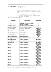
..." N N N Parallel Port Address Parallel Port Address Parallel Port Address Parallel Port Address N N USB Support USB Support USB Support USB Support &Front USB Ports USB Support &Front USB Ports USB Support &Rear USB Ports USB Support &Rear USB Ports USB Support &Rear USB Ports USB Support &Rear USB Ports USB Support &Rear USB Ports USB Support Lenovo BIOS Windows Management Instrumentation Interface Deployment Guide for Desktop 6 Table 4. Available BIOS setting...
..." N N N Parallel Port Address Parallel Port Address Parallel Port Address Parallel Port Address N N USB Support USB Support USB Support USB Support &Front USB Ports USB Support &Front USB Ports USB Support &Rear USB Ports USB Support &Rear USB Ports USB Support &Rear USB Ports USB Support &Rear USB Ports USB Support &Rear USB Ports USB Support Lenovo BIOS Windows Management Instrumentation Interface Deployment Guide for Desktop 6 Table 4. Available BIOS setting...
BIOS Windows Management Instrumentation Interface Deployment Guide
Page 15
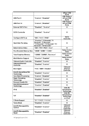
USB Port 9 USB Port 10 External SATA Port SATA Controller "Enabled","Disabled" "Enabled","Disabled" "Disabled", "Enabled" "Disabled", "Enabled" Configure SATA as Hard Disk Pre-...VT-d "Disabled","Enabled" TxT C State Support Turbo Mode Intel(R) Manageability Control Intel(R) Manageability Reset @Copyright Lenovo 2011 "Disabled","Enabled" "C1","C1C3","C1C3C6" "Disabled","Enabled" "Disabled","Enabled" "Disabled","Enabled" &Rear USB Ports USB Support &Front USB Ports USB Support &Front USB Ports N N SATA Controller N N Select Active Video Select Active Video Select Active Video N N Onboard...
USB Port 9 USB Port 10 External SATA Port SATA Controller "Enabled","Disabled" "Enabled","Disabled" "Disabled", "Enabled" "Disabled", "Enabled" Configure SATA as Hard Disk Pre-...VT-d "Disabled","Enabled" TxT C State Support Turbo Mode Intel(R) Manageability Control Intel(R) Manageability Reset @Copyright Lenovo 2011 "Disabled","Enabled" "C1","C1C3","C1C3C6" "Disabled","Enabled" "Disabled","Enabled" "Disabled","Enabled" &Rear USB Ports USB Support &Front USB Ports USB Support &Front USB Ports N N SATA Controller N N Select Active Video Select Active Video Select Active Video N N Onboard...
BIOS Windows Management Instrumentation Interface Deployment Guide
Page 16
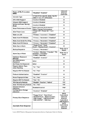
... Detection "No","Yes" Enabled/Disabled "Disabled","Enabled" Primary Boot Sequence "Floppy Drive", "Hard Drive", "CD/DVD Drive", "Network Card", "USB Floppy", "USB Hard Disk", "USB CD/DVD", "USB Key" Automatic Boot Sequence N N N TXT TXT PAP N SATA Controller& Onboard Ethernet Controller& USB Support SATA Controller& Onboard Ethernet Lenovo BIOS Windows Management Instrumentation Interface Deployment Guide for Desktop 8
... Detection "No","Yes" Enabled/Disabled "Disabled","Enabled" Primary Boot Sequence "Floppy Drive", "Hard Drive", "CD/DVD Drive", "Network Card", "USB Floppy", "USB Hard Disk", "USB CD/DVD", "USB Key" Automatic Boot Sequence N N N TXT TXT PAP N SATA Controller& Onboard Ethernet Controller& USB Support SATA Controller& Onboard Ethernet Lenovo BIOS Windows Management Instrumentation Interface Deployment Guide for Desktop 8
BIOS Windows Management Instrumentation Interface Deployment Guide
Page 17
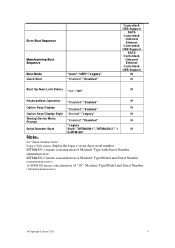
Error Boot Sequence Manufacturing Boot Sequence Boot Mode Quick Boot "Auto","UEFI","Legacy" "Enabled","Disabled" Controller& USB Support SATA Controller& Onboard Ethernet Controller& USB Support SATA Controller& Onboard Ethernet Controller& USB Support N N Boot Up Num-Lock Status "On","Off" N Keyboardless Operation "Disabled","Enabled" N Option Keys Display "Disabled","Enabled" N Option Keys Display Style ... of Machine Type/Model and Serial Number (mmmmmmmsssssss) 1S-MTM-SN means concatenation of "1S", Machine Type/Model and Serial Number (1Smmmmmmmsssssss) @Copyright Lenovo 2011 9
Error Boot Sequence Manufacturing Boot Sequence Boot Mode Quick Boot "Auto","UEFI","Legacy" "Enabled","Disabled" Controller& USB Support SATA Controller& Onboard Ethernet Controller& USB Support SATA Controller& Onboard Ethernet Controller& USB Support N N Boot Up Num-Lock Status "On","Off" N Keyboardless Operation "Disabled","Enabled" N Option Keys Display "Disabled","Enabled" N Option Keys Display Style ... of Machine Type/Model and Serial Number (mmmmmmmsssssss) 1S-MTM-SN means concatenation of "1S", Machine Type/Model and Serial Number (1Smmmmmmmsssssss) @Copyright Lenovo 2011 9
BIOS Windows Management Instrumentation Interface Deployment Guide
Page 20
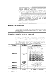
English US, English UK, Lenovo BIOS Windows Management Instrumentation Interface Deployment Guide for Desktop 12 To set a new boot order, use the Lenovo_SetBiosSetting class, then use the Lenovo_SaveBiosSettings class to ... drive is ″pap,abc,def,ascii,us ″- Example: Change primary boot sequence, Primary Boot Sequence,CD/DVD Drive:Hard Drive:Network Card:USB Key:USB Floppy:USB Hard Disk Restoring default settings To restore default BIOS settings, use the Lenovo_LoadDefaultSettings class, and then use the Lenovo_SaveBiosSetting class to save the settings...
English US, English UK, Lenovo BIOS Windows Management Instrumentation Interface Deployment Guide for Desktop 12 To set a new boot order, use the Lenovo_SetBiosSetting class, then use the Lenovo_SaveBiosSettings class to ... drive is ″pap,abc,def,ascii,us ″- Example: Change primary boot sequence, Primary Boot Sequence,CD/DVD Drive:Hard Drive:Network Card:USB Key:USB Floppy:USB Hard Disk Restoring default settings To restore default BIOS settings, use the Lenovo_LoadDefaultSettings class, and then use the Lenovo_SaveBiosSetting class to save the settings...
Hardware Maintenance Manual
Page 5
... microprocessor 83 Replacing the system board 86 Replacing the system fan assembly 88 Replacing the internal speaker 91 Replacing the front audio and USB assembly . . 92 Replacing the ac power adapter 94 Replacing the ac power adapter bracket . . . . 95 Completing the ...parts replacement 98 Chapter 9. FRU lists 99 © Copyright Lenovo 2011, 2012 iii General checkout . . . . . 33 Checking for DOS 38 Creating a diagnostic disc 38 Running the diagnostic program from the Setup Utility program...
... microprocessor 83 Replacing the system board 86 Replacing the system fan assembly 88 Replacing the internal speaker 91 Replacing the front audio and USB assembly . . 92 Replacing the ac power adapter 94 Replacing the ac power adapter bracket . . . . 95 Completing the ...parts replacement 98 Chapter 9. FRU lists 99 © Copyright Lenovo 2011, 2012 iii General checkout . . . . . 33 Checking for DOS 38 Creating a diagnostic disc 38 Running the diagnostic program from the Setup Utility program...
Hardware Maintenance Manual
Page 49
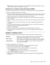
... CMOS) This section provides instructions on the device you want to enable or disable, do the following : • Select USB Setup to enable or disable a USB device. • Select ATA Drive Setup to 64 alphabetic and numeric characters. Turn on the computer and leave it on ...For more information, see "Password considerations" on page 98. Then, disconnect all attached devices and the computer. When this option to the USB connector cannot be accessed. See "Completing the parts replacement" on page 42. See "Exiting from electrical outlets and disconnect all devices connected to...
... CMOS) This section provides instructions on the device you want to enable or disable, do the following : • Select USB Setup to enable or disable a USB device. • Select ATA Drive Setup to 64 alphabetic and numeric characters. Turn on the computer and leave it on ...For more information, see "Password considerations" on page 98. Then, disconnect all attached devices and the computer. When this option to the USB connector cannot be accessed. See "Completing the parts replacement" on page 42. See "Exiting from electrical outlets and disconnect all devices connected to...
Hardware Maintenance Manual
Page 59
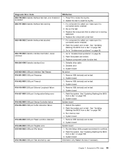
...system. Reboot the system 2. Flash the system and re-test. See "Updating (flashing) the BIOS from a disc" on page 186. 3. System board 1. Remove USB device(s) and re-test. 2. Symptom-to "Undetermined problems" on page 66. 1. Re-run the test. 3. Go to review the log file. 2. Diskette ...program and check for conflicts. 2. Flash the system. System board Information only Restart the test, if necessary. Flash the system and re-test. Remove USB device(s) and re-test 2. See "Updating (flashing) the BIOS from a disc" on page 186. 3. Replace component under test. 1. Restart ...
...system. Reboot the system 2. Flash the system and re-test. See "Updating (flashing) the BIOS from a disc" on page 186. 3. System board 1. Remove USB device(s) and re-test. 2. Symptom-to "Undetermined problems" on page 66. 1. Re-run the test. 3. Go to review the log file. 2. Diskette ...program and check for conflicts. 2. Flash the system. System board Information only Restart the test, if necessary. Flash the system and re-test. Remove USB device(s) and re-test 2. See "Updating (flashing) the BIOS from a disc" on page 186. 3. Replace component under test. 1. Restart ...
Hardware Maintenance Manual
Page 60
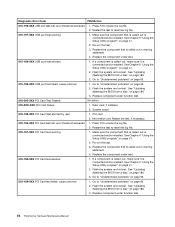
... connected and/or enabled. See Chapter 6 "Using the Setup Utility program" on page 66. 2. Replace the component under function test. 54 ThinkCentre Hardware Maintenance Manual Go to "Undetermined problems" on page 186. 3. See "Updating (flashing) the BIOS from a disc" on page 66. 015-199...function test. 018-000-XXX PCI Card Test Passed No action 018-0XX-XXX PCI Card Failure 1. Diagnostic Error Code FRU/Action 015-196-XXX USB port test halt, error threshold exceeded 1. See "Updating (flashing) the BIOS from a disc" on page 186. 3. Information only Restart the test...
... connected and/or enabled. See Chapter 6 "Using the Setup Utility program" on page 66. 2. Replace the component under function test. 54 ThinkCentre Hardware Maintenance Manual Go to "Undetermined problems" on page 186. 3. See "Updating (flashing) the BIOS from a disc" on page 66. 015-199...function test. 018-000-XXX PCI Card Test Passed No action 018-0XX-XXX PCI Card Failure 1. Diagnostic Error Code FRU/Action 015-196-XXX USB port test halt, error threshold exceeded 1. See "Updating (flashing) the BIOS from a disc" on page 186. 3. Information only Restart the test...
Hardware Maintenance Manual
Page 75
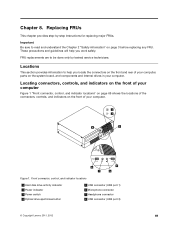
.... Front connector, control, and indicator locations 1 Hard disk drive activity indicator 2 Power indicator 3 Power switch 4 Optical drive eject/close button 5 USB connector (USB port 1) 6 Microphone connector 7 Headphone connector 8 USB connector (USB port 2) © Copyright Lenovo 2011, 2012 69 These precautions and guidelines will help you work safely. Figure 1. Chapter 8. Important Be sure to be done...
.... Front connector, control, and indicator locations 1 Hard disk drive activity indicator 2 Power indicator 3 Power switch 4 Optical drive eject/close button 5 USB connector (USB port 1) 6 Microphone connector 7 Headphone connector 8 USB connector (USB port 2) © Copyright Lenovo 2011, 2012 69 These precautions and guidelines will help you work safely. Figure 1. Chapter 8. Important Be sure to be done...
Hardware Maintenance Manual
Page 76
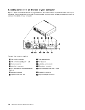
...-release button 9 PCI card slot 10 Audio line-out connector 11 Microphone connector 12 USB connectors (USB ports 3 and 4) 13 DisplayPort connector 14 ac power adapter connector 70 ThinkCentre Hardware Maintenance Manual Figure 2. Rear connector locations 1 VGA monitor connector 2 USB connectors (USB ports 5 to connect the cables on the rear of the connectors on your...
...-release button 9 PCI card slot 10 Audio line-out connector 11 Microphone connector 12 USB connectors (USB ports 3 and 4) 13 DisplayPort connector 14 ac power adapter connector 70 ThinkCentre Hardware Maintenance Manual Figure 2. Rear connector locations 1 VGA monitor connector 2 USB connectors (USB ports 5 to connect the cables on the rear of the connectors on your...

Hardware Maintenance Manual
Page 78
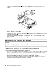
... connecting USB ports 1 and 2 on the front bezel, LED indicators and power switch, and microphone and headphone connectors on how to open your computer or attempt any repair before reading and understanding the "Important safety information" in the ThinkCentre User Guide. To obtain a copy of the ThinkCentre User Guide, go to: http://www.lenovo...
... connecting USB ports 1 and 2 on the front bezel, LED indicators and power switch, and microphone and headphone connectors on how to open your computer or attempt any repair before reading and understanding the "Important safety information" in the ThinkCentre User Guide. To obtain a copy of the ThinkCentre User Guide, go to: http://www.lenovo...
Hardware Maintenance Manual
Page 98
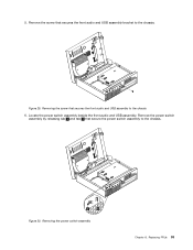
... understanding the "Important safety information" in the ThinkCentre User Guide. To replace the front audio and USB assembly, do the following: 1. Remove all media from the chassis. Open the computer cover. Disconnect the front audio and USB assembly cables from electrical outlets and disconnect all ...to replace the front audio and USB assembly. See "Locating parts on the system board" on page 73. 4. See "Removing and reinstalling the front bezel" on page 71. 8. To obtain a copy of the ThinkCentre User Guide, go to: http://www.lenovo.com/ThinkCentreUserGuides This section provides ...
... understanding the "Important safety information" in the ThinkCentre User Guide. To replace the front audio and USB assembly, do the following: 1. Remove all media from the chassis. Open the computer cover. Disconnect the front audio and USB assembly cables from electrical outlets and disconnect all ...to replace the front audio and USB assembly. See "Locating parts on the system board" on page 73. 4. See "Removing and reinstalling the front bezel" on page 71. 8. To obtain a copy of the ThinkCentre User Guide, go to: http://www.lenovo.com/ThinkCentreUserGuides This section provides ...
Hardware Maintenance Manual
Page 99
Figure 29. Figure 30. Removing the power switch assembly Chapter 8. 5. Removing the screw that secure the power switch assembly to the chassis. Remove the power switch assembly by releasing tab 1 and tab 2 that secures the front audio and USB assembly to the chassis. Remove the screw that secures the front audio and USB assembly bracket to the chassis 6. Locate the power switch assembly beside the front audio and USB assembly. Replacing FRUs 93
Figure 29. Figure 30. Removing the power switch assembly Chapter 8. 5. Removing the screw that secure the power switch assembly to the chassis. Remove the power switch assembly by releasing tab 1 and tab 2 that secures the front audio and USB assembly to the chassis. Remove the screw that secures the front audio and USB assembly bracket to the chassis 6. Locate the power switch assembly beside the front audio and USB assembly. Replacing FRUs 93
Hardware Maintenance Manual
Page 100
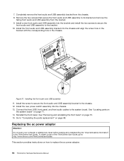
...Install the new power switch assembly into the bracket and install the two screws to secure the front audio and USB assembly to replace the ac power adapter. 94 ThinkCentre Hardware Maintenance Manual See "Removing and reinstalling the front bezel" on page 71. 14. Go to the ...audio and USB assembly to the chassis. 12. Install the screw to secure the front audio and USB assembly bracket to its bracket and remove the failing front audio and USB assembly from the chassis. 8. To obtain a copy of the ThinkCentre User Guide, go to: http://www.lenovo.com/ThinkCentreUserGuides...
...Install the new power switch assembly into the bracket and install the two screws to secure the front audio and USB assembly to replace the ac power adapter. 94 ThinkCentre Hardware Maintenance Manual See "Removing and reinstalling the front bezel" on page 71. 14. Go to the ...audio and USB assembly to the chassis. 12. Install the screw to secure the front audio and USB assembly bracket to its bracket and remove the failing front audio and USB assembly from the chassis. 8. To obtain a copy of the ThinkCentre User Guide, go to: http://www.lenovo.com/ThinkCentreUserGuides...
Hardware Maintenance Manual
Page 118
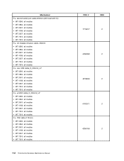
... 2491: all modles • MT 4168: all modles • MT 5067: all modles • MT 7516: all modles • MT 7519: all modles Fru, rear USB cable_R_200mm_LP • MT 0266: all modles • MT 0384: all modles • MT 2491: all modles • MT 4168: all modles • MT 5067: all...; MT 2491: all modles • MT 4168: all modles • MT 5067: all modles • MT 7516: all modles • MT 7519: all modles 112 ThinkCentre Hardware Maintenance Manual FRU # CRU 71Y6217 2 43N9093 2 42Y8006 2 41R3311 2 43N9149 2
... 2491: all modles • MT 4168: all modles • MT 5067: all modles • MT 7516: all modles • MT 7519: all modles Fru, rear USB cable_R_200mm_LP • MT 0266: all modles • MT 0384: all modles • MT 2491: all modles • MT 4168: all modles • MT 5067: all...; MT 2491: all modles • MT 4168: all modles • MT 5067: all modles • MT 7516: all modles • MT 7519: all modles 112 ThinkCentre Hardware Maintenance Manual FRU # CRU 71Y6217 2 43N9093 2 42Y8006 2 41R3311 2 43N9149 2
Hardware Maintenance Manual
Page 122
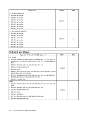
... • MT 5067: all modles • MT 7516: all modles • MT 7519: all modles Mechanical FRU # 45K6415 03T9610 Keyboard and Mouse Keyboard - Preferred Pro USB Keyboard US English • MT 0266: B6M B7U B7M B8U B8M A1H A2H A3A A4A C8G C9G B9G C1G A5G A6G A7G A8G A9G B1G... • MT 7516: B7G A5G A6G A7G A8G A9G B1G B2G B3G • MT 7519: A2G A3G A9G B1G FRU # 41A5289 41A5290 CRU 2 2 CRU 1 1 116 ThinkCentre Hardware Maintenance Manual
... • MT 5067: all modles • MT 7516: all modles • MT 7519: all modles Mechanical FRU # 45K6415 03T9610 Keyboard and Mouse Keyboard - Preferred Pro USB Keyboard US English • MT 0266: B6M B7U B7M B8U B8M A1H A2H A3A A4A C8G C9G B9G C1G A5G A6G A7G A8G A9G B1G... • MT 7516: B7G A5G A6G A7G A8G A9G B1G B2G B3G • MT 7519: A2G A3G A9G B1G FRU # 41A5289 41A5290 CRU 2 2 CRU 1 1 116 ThinkCentre Hardware Maintenance Manual
Hardware Maintenance Manual
Page 124
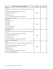
Keyboard - Preferred Pro USB Keyboard Bulgarian • MT 0266: C8G C9G B9G C1G A5G A6G A7G A8G A9G B1G B2G B3G D2G D9G • MT 0384: A9G A7G A8G ...; MT 7516: B7G A5G A6G A7G A8G A9G B1G B2G B3G • MT 7519: A2G A3G A9G B1G FRU # 41A5295 41A5296 41A5297 41A5298 CRU 1 1 1 1 118 ThinkCentre Hardware Maintenance Manual
Keyboard - Preferred Pro USB Keyboard Bulgarian • MT 0266: C8G C9G B9G C1G A5G A6G A7G A8G A9G B1G B2G B3G D2G D9G • MT 0384: A9G A7G A8G ...; MT 7516: B7G A5G A6G A7G A8G A9G B1G B2G B3G • MT 7519: A2G A3G A9G B1G FRU # 41A5295 41A5296 41A5297 41A5298 CRU 1 1 1 1 118 ThinkCentre Hardware Maintenance Manual
Hardware Maintenance Manual
Page 125
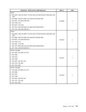
Keyboard - Preferred Pro USB Keyboard Dutch • MT 0266: C8G C9G B9G C1G A5G A6G A7G A8G A9G B1G B2G B3G D2G D9G • MT 0384: A9G A7G A8G ...
Keyboard - Preferred Pro USB Keyboard Dutch • MT 0266: C8G C9G B9G C1G A5G A6G A7G A8G A9G B1G B2G B3G D2G D9G • MT 0384: A9G A7G A8G ...
Hardware Maintenance Manual
Page 126
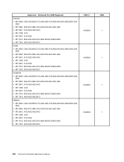
Preferred Pro USB Keyboard German • MT 0266: C8G C9G B9G C1G A5G A6G A7G A8G A9G B1G B2G B3G D2G D9G • MT 0384: A9G A7G A8G ...; MT 7516: B7G A5G A6G A7G A8G A9G B1G B2G B3G • MT 7519: A2G A3G A9G B1G FRU # 41A5303 41A5304 41A5305 41A5306 CRU 1 1 1 1 120 ThinkCentre Hardware Maintenance Manual Keyboard -
Preferred Pro USB Keyboard German • MT 0266: C8G C9G B9G C1G A5G A6G A7G A8G A9G B1G B2G B3G D2G D9G • MT 0384: A9G A7G A8G ...; MT 7516: B7G A5G A6G A7G A8G A9G B1G B2G B3G • MT 7519: A2G A3G A9G B1G FRU # 41A5303 41A5304 41A5305 41A5306 CRU 1 1 1 1 120 ThinkCentre Hardware Maintenance Manual Keyboard -

