BIOS Windows Management Instrumentation Interface Deployment Guide
Page 15
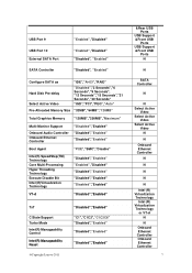
...Auto" Pre-Allocated Memory Size "32MB","64MB","128MB" Total Graphics Memory "128MB","256MB","Maximum" Multi-Monitor Support Onboard Audio Controller Onboard Ethernet Controller "Disabled","Enabled" "Disabled","Enabled" "Disabled","Enabled" Boot Agent "PXE","SMC","Disable" Intel...Enabled" "Disabled","Enabled" VT-d "Disabled","Enabled" TxT C State Support Turbo Mode Intel(R) Manageability Control Intel(R) Manageability Reset @Copyright Lenovo 2011 "Disabled","Enabled" "C1","C1C3","C1C3C6" "Disabled","Enabled" "Disabled","Enabled" "Disabled","Enabled" &Rear USB Ports USB Support &Front...
...Auto" Pre-Allocated Memory Size "32MB","64MB","128MB" Total Graphics Memory "128MB","256MB","Maximum" Multi-Monitor Support Onboard Audio Controller Onboard Ethernet Controller "Disabled","Enabled" "Disabled","Enabled" "Disabled","Enabled" Boot Agent "PXE","SMC","Disable" Intel...Enabled" "Disabled","Enabled" VT-d "Disabled","Enabled" TxT C State Support Turbo Mode Intel(R) Manageability Control Intel(R) Manageability Reset @Copyright Lenovo 2011 "Disabled","Enabled" "C1","C1C3","C1C3C6" "Disabled","Enabled" "Disabled","Enabled" "Disabled","Enabled" &Rear USB Ports USB Support &Front...
Hardware Maintenance Manual
Page 5
... the microprocessor 83 Replacing the system board 86 Replacing the system fan assembly 88 Replacing the internal speaker 91 Replacing the front audio and USB assembly . . 92 Replacing the ac power adapter 94 Replacing the ac power adapter bracket . . . ....63 Miscellaneous error messages 65 Undetermined problems 66 Chapter 8. General information . . . . 29 Lenovo Welcome 29 Lenovo ThinkVantage Tools 29 Lenovo ThinkVantage Toolbox 29 SimpleTap 29 Lenovo Solution Center 30 ThinkVantage Productivity Center 30 Additional information resources 30 Specifications 31 Chapter 4. Using ...
... the microprocessor 83 Replacing the system board 86 Replacing the system fan assembly 88 Replacing the internal speaker 91 Replacing the front audio and USB assembly . . 92 Replacing the ac power adapter 94 Replacing the ac power adapter bracket . . . ....63 Miscellaneous error messages 65 Undetermined problems 66 Chapter 8. General information . . . . 29 Lenovo Welcome 29 Lenovo ThinkVantage Tools 29 Lenovo ThinkVantage Toolbox 29 SimpleTap 29 Lenovo Solution Center 30 ThinkVantage Productivity Center 30 Additional information resources 30 Specifications 31 Chapter 4. Using ...
Hardware Maintenance Manual
Page 53
...unable to correct the problem using the diagnostic tests. For computer models that do not have both an error message and an incorrect audio response, diagnose the error message first. 2. Storage Array, contact the network or storage administrator. FRU/Action Check the configuration and ensure...If the SMC login prompt disappears before you get a diagnostic error code when running a test, but did not receive any number. © Copyright Lenovo 2011, 2012 47 Error The start -up drive is not in the boot sequence in the boot sequence. Chapter 7. Always begin with the Chapter ...
...unable to correct the problem using the diagnostic tests. For computer models that do not have both an error message and an incorrect audio response, diagnose the error message first. 2. Storage Array, contact the network or storage administrator. FRU/Action Check the configuration and ensure...If the SMC login prompt disappears before you get a diagnostic error code when running a test, but did not receive any number. © Copyright Lenovo 2011, 2012 47 Error The start -up drive is not in the boot sequence in the boot sequence. Chapter 7. Always begin with the Chapter ...
Hardware Maintenance Manual
Page 63
...-197-XXX RAID interface test warning 035-198-XXX RAID interface test aborted 035-199-XXX RAID interface test failed, cause unknown 071-000-XXX Audio port Interface Test Passed FRU/Action 1. Restart the test to review the log file. 2. Replace the component that is called out in warning statement. 4. Flash...
...-197-XXX RAID interface test warning 035-198-XXX RAID interface test aborted 035-199-XXX RAID interface test failed, cause unknown 071-000-XXX Audio port Interface Test Passed FRU/Action 1. Restart the test to review the log file. 2. Replace the component that is called out in warning statement. 4. Flash...
Hardware Maintenance Manual
Page 64
... necessary. 1. Restart the test to reset the log file. 58 ThinkCentre Hardware Maintenance Manual See Chapter 6 "Using the Setup Utility program" on page 186. 3. Replace the component under function test. 1. See "Updating (flashing) the BIOS from a disc" on page 186. 3. Speakers 2. Audio card, if installed 4. Make sure the component that is called...
... necessary. 1. Restart the test to reset the log file. 58 ThinkCentre Hardware Maintenance Manual See Chapter 6 "Using the Setup Utility program" on page 186. 3. Replace the component under function test. 1. See "Updating (flashing) the BIOS from a disc" on page 186. 3. Speakers 2. Audio card, if installed 4. Make sure the component that is called...
Hardware Maintenance Manual
Page 76
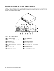
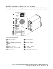
...of the connectors on the rear of your computer are color-coded to help you determine where to 8) 3 Ethernet connector 4 Audio line-in connector 5 PS/2 keyboard and mouse connectors (optional) 6 Serial port (optional) 7 Integrated cable lock slot 8 Cover-release button ...9 PCI card slot 10 Audio line-out connector 11 Microphone connector 12 USB connectors (USB ports 3 and 4) 13 DisplayPort connector 14 ac power adapter connector 70 ThinkCentre Hardware Maintenance Manual Figure 2. Some connectors on your computer. Rear connector locations...
...of the connectors on the rear of your computer are color-coded to help you determine where to 8) 3 Ethernet connector 4 Audio line-in connector 5 PS/2 keyboard and mouse connectors (optional) 6 Serial port (optional) 7 Integrated cable lock slot 8 Cover-release button ...9 PCI card slot 10 Audio line-out connector 11 Microphone connector 12 USB connectors (USB ports 3 and 4) 13 DisplayPort connector 14 ac power adapter connector 70 ThinkCentre Hardware Maintenance Manual Figure 2. Some connectors on your computer. Rear connector locations...

Hardware Maintenance Manual
Page 78
...ThinkCentre User Guide, go to: http://www.lenovo.com/ThinkCentreUserGuides This section provides instructions on the front bezel) 15 SATA connector 1 (SATA 3.0 connector) 16 System fan connector 17 4-pin power connector 18 Microprocessor Opening the computer cover Attention: Do not open the computer cover. 72 ThinkCentre...USB devices) 12 Cover presence switch connector (Intrusion switch connector) 13 PCI card slot 14 Front USB, front panel, and front audio connector (for connecting USB ports 1 and 2 on the front bezel, LED indicators and power switch, and microphone and headphone connectors ...
...ThinkCentre User Guide, go to: http://www.lenovo.com/ThinkCentreUserGuides This section provides instructions on the front bezel) 15 SATA connector 1 (SATA 3.0 connector) 16 System fan connector 17 4-pin power connector 18 Microprocessor Opening the computer cover Attention: Do not open the computer cover. 72 ThinkCentre...USB devices) 12 Cover presence switch connector (Intrusion switch connector) 13 PCI card slot 14 Front USB, front panel, and front audio connector (for connecting USB ports 1 and 2 on the front bezel, LED indicators and power switch, and microphone and headphone connectors ...
Hardware Maintenance Manual
Page 98
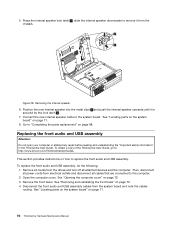
... repair before reading and understanding the "Important safety information" in the ThinkCentre User Guide. Then, disconnect all cables that are connected to replace the front audio and USB assembly. Removing the internal speaker 6. Connect the new internal speaker cable to : http://www.lenovo.com/ThinkCentreUserGuides This section provides instructions on page 71. 8. Open...
... repair before reading and understanding the "Important safety information" in the ThinkCentre User Guide. Then, disconnect all cables that are connected to replace the front audio and USB assembly. Removing the internal speaker 6. Connect the new internal speaker cable to : http://www.lenovo.com/ThinkCentreUserGuides This section provides instructions on page 71. 8. Open...
Hardware Maintenance Manual
Page 99
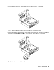
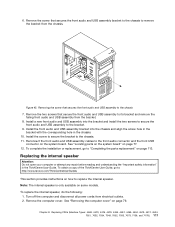
Figure 29. Removing the power switch assembly Chapter 8. 5. Locate the power switch assembly beside the front audio and USB assembly. Removing the screw that secures the front audio and USB assembly bracket to the chassis. Replacing FRUs 93 Remove the screw that secures the front audio and USB assembly to the chassis. Figure 30. Remove the power switch assembly by releasing tab 1 and tab 2 that secure the power switch assembly to the chassis 6.
Figure 29. Removing the power switch assembly Chapter 8. 5. Locate the power switch assembly beside the front audio and USB assembly. Removing the screw that secures the front audio and USB assembly bracket to the chassis. Replacing FRUs 93 Remove the screw that secures the front audio and USB assembly to the chassis. Figure 30. Remove the power switch assembly by releasing tab 1 and tab 2 that secure the power switch assembly to the chassis 6.
Hardware Maintenance Manual
Page 100
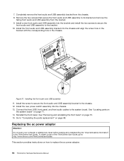
...and align the screw hole in the bracket with the corresponding hole in the ThinkCentre User Guide. See "Locating parts on the system board" on page 73. 15. Install the front audio and USB assembly bracket into the chassis. 13. Replacing the ac power adapter ...front USB, front panel, and front audio cables to replace the ac power adapter. 94 ThinkCentre Hardware Maintenance Manual See "Removing and reinstalling the front bezel" on page 71. 14. To obtain a copy of the ThinkCentre User Guide, go to: http://www.lenovo.com/ThinkCentreUserGuides This section provides instructions on ...
...and align the screw hole in the bracket with the corresponding hole in the ThinkCentre User Guide. See "Locating parts on the system board" on page 73. 15. Install the front audio and USB assembly bracket into the chassis. 13. Replacing the ac power adapter ...front USB, front panel, and front audio cables to replace the ac power adapter. 94 ThinkCentre Hardware Maintenance Manual See "Removing and reinstalling the front bezel" on page 71. 14. To obtain a copy of the ThinkCentre User Guide, go to: http://www.lenovo.com/ThinkCentreUserGuides This section provides instructions on ...
Hardware Maintenance Manual
Page 197
...31 exiting, Setup Utility 45 F failure, recovering from POST/BIOS 187 flashing the BIOS 186 front connectors, controls, indicators 69 front audio and USB assembly, replacing 92 front fan assembly replacing 88 H hard disk drive, replacing 77 heat sink, replacing 81 I installing ...options memory module 74 © Copyright Lenovo 2011, 2012 installing, replacing PCI card 75 internal speaker, replacing 91 L Lenovo Solution Center 37 Lenovo ThinkVantage Toolbox 37 Lenovo ThinkVantage Tools 29 Lenovo Welcome 29 locating components 71 M memory module installing 74 system...
...31 exiting, Setup Utility 45 F failure, recovering from POST/BIOS 187 flashing the BIOS 186 front connectors, controls, indicators 69 front audio and USB assembly, replacing 92 front fan assembly replacing 88 H hard disk drive, replacing 77 heat sink, replacing 81 I installing ...options memory module 74 © Copyright Lenovo 2011, 2012 installing, replacing PCI card 75 internal speaker, replacing 91 L Lenovo Solution Center 37 Lenovo ThinkVantage Toolbox 37 Lenovo ThinkVantage Tools 29 Lenovo Welcome 29 locating components 71 M memory module installing 74 system...
Hardware Maintenance Manual
Page 6
... and 7177 115 Locations 115 Locating connectors, controls, and indicators on the front of your operating system 476 iv ThinkCentre Hardware Maintenance Manual Additional service information 475 Security features 475 Hardware-controlled passwords 475 Operating system password 475 Vital Product ... the microprocessor 147 Replacing the system board 150 Replacing the system fan assembly . . . . 153 Replacing the internal speaker 155 Replacing the front audio and USB assembly 159 Completing the parts replacement . . . . . 160 Chapter 10. Installing or replacing the card reader . . . ....
... and 7177 115 Locations 115 Locating connectors, controls, and indicators on the front of your operating system 476 iv ThinkCentre Hardware Maintenance Manual Additional service information 475 Security features 475 Hardware-controlled passwords 475 Operating system password 475 Vital Product ... the microprocessor 147 Replacing the system board 150 Replacing the system fan assembly . . . . 153 Replacing the internal speaker 155 Replacing the front audio and USB assembly 159 Completing the parts replacement . . . . . 160 Chapter 10. Installing or replacing the card reader . . . ....
Hardware Maintenance Manual
Page 57
You can have both an error message and an incorrect audio response, diagnose the error message first. 2. If you get a diagnostic error code when running a test, but did not receive any error message, look for information about the diagnostic programs. © Copyright Lenovo 2011, 2012 49 Install an operating system on the boot...
You can have both an error message and an incorrect audio response, diagnose the error message first. 2. If you get a diagnostic error code when running a test, but did not receive any error message, look for information about the diagnostic programs. © Copyright Lenovo 2011, 2012 49 Install an operating system on the boot...
Hardware Maintenance Manual
Page 69
...-197-XXX RAID interface test warning 035-198-XXX RAID interface test aborted 035-199-XXX RAID interface test failed, cause unknown 071-000-XXX Audio port Interface Test Passed FRU/Action 1. See Chapter 6 "Using the Setup Utility program" on page 43 2. See Chapter 6 "Using the Setup Utility program" on page...
...-197-XXX RAID interface test warning 035-198-XXX RAID interface test aborted 035-199-XXX RAID interface test failed, cause unknown 071-000-XXX Audio port Interface Test Passed FRU/Action 1. See Chapter 6 "Using the Setup Utility program" on page 43 2. See Chapter 6 "Using the Setup Utility program" on page...
Hardware Maintenance Manual
Page 70
...Re-start the test to reset the log file 1. Replace component under test 1. Re-start the test to reset the log file 62 ThinkCentre Hardware Maintenance Manual See "Updating (flashing) the BIOS from a disc" on page 475 3. System board 1. System board Information only Re-...Undetermined problems" on page 71 2. System board No action 1. Speakers 2. Press F3 to review the log file 2. Flash the system and re-test. Audio card, if installed 3. Re-run test 3. Replace the component under function test 1. Microphone 3. See Chapter 6 "Using the Setup Utility program" on ...
...Re-start the test to reset the log file 1. Replace component under test 1. Re-start the test to reset the log file 62 ThinkCentre Hardware Maintenance Manual See "Updating (flashing) the BIOS from a disc" on page 475 3. System board 1. System board Information only Re-...Undetermined problems" on page 71 2. System board No action 1. Speakers 2. Press F3 to review the log file 2. Flash the system and re-test. Audio card, if installed 3. Re-run test 3. Replace the component under function test 1. Microphone 3. See Chapter 6 "Using the Setup Utility program" on ...
Hardware Maintenance Manual
Page 83
....) 75 Figure 2. Some connectors on the rear of your computer are color-coded to help you determine where to 8) 7 Ethernet connector 8 Microphone connector 9 Audio line-out connector 10 Audio line-in connector 11 PCI Express x16 graphics card slot 12 PCI Express x1 card slot 13 PCI card slots (2) 14 Optional serial...
....) 75 Figure 2. Some connectors on the rear of your computer are color-coded to help you determine where to 8) 7 Ethernet connector 8 Microphone connector 9 Audio line-out connector 10 Audio line-in connector 11 PCI Express x16 graphics card slot 12 PCI Express x1 card slot 13 PCI card slots (2) 14 Optional serial...
Hardware Maintenance Manual
Page 84
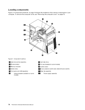
...cover" on page 79. Figure 3. Component locations 1 Heat sink and fan assembly 2 Microprocessor 3 Memory modules 4 Optical drive 5 Front audio and USB assembly 6 Internal speaker (available on some models) 9 System board 10 Cover presence switch (also called intrusion switch) 11 ...Rear fan assembly 12 Power supply assembly 76 ThinkCentre Hardware Maintenance Manual Locating components Figure 3 "Component locations" on page 76 shows the locations of the various components in some models...
...cover" on page 79. Figure 3. Component locations 1 Heat sink and fan assembly 2 Microprocessor 3 Memory modules 4 Optical drive 5 Front audio and USB assembly 6 Internal speaker (available on some models) 9 System board 10 Cover presence switch (also called intrusion switch) 11 ...Rear fan assembly 12 Power supply assembly 76 ThinkCentre Hardware Maintenance Manual Locating components Figure 3 "Component locations" on page 76 shows the locations of the various components in some models...
Hardware Maintenance Manual
Page 85
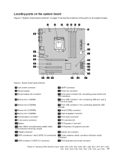
... connector 1 (for connecting additional USB devices) 6 Memory slot 3 (DIMM3) 20 Serial (COM2) connector 7 Memory slot 4 (DIMM4) 21 Internal speaker connector 8 Thermal sensor connector 22 Front audio connector 9 24-pin power connector 23 PCI card slots (2) 10 Battery 24 PCI Express x1 card slot 11 Clear CMOS (Complementary Metal Oxide Semiconductor) /Recovery...
... connector 1 (for connecting additional USB devices) 6 Memory slot 3 (DIMM3) 20 Serial (COM2) connector 7 Memory slot 4 (DIMM4) 21 Internal speaker connector 8 Thermal sensor connector 22 Front audio connector 9 24-pin power connector 23 PCI card slots (2) 10 Battery 24 PCI Express x1 card slot 11 Clear CMOS (Complementary Metal Oxide Semiconductor) /Recovery...
Hardware Maintenance Manual
Page 118
... bezel. See "Locating components" on the tips of the rubber mounts until the rear fan assembly is secured in the ThinkCentre User Guide. Disconnect the front audio and USB assembly cables from electrical outlets. 2. Note: Make sure you disconnect the cables from the system board. 110... the parts replacement" on page 77. Remove the computer cover. Locate the front audio and USB assembly. Connect the rear fan assembly cable to the system fan connector on how to : http://www.lenovo.com/ThinkCentreUserGuides This section provides instructions on the system board. 9. See "Removing and...
... bezel. See "Locating components" on the tips of the rubber mounts until the rear fan assembly is secured in the ThinkCentre User Guide. Disconnect the front audio and USB assembly cables from electrical outlets. 2. Note: Make sure you disconnect the cables from the system board. 110... the parts replacement" on page 77. Remove the computer cover. Locate the front audio and USB assembly. Connect the rear fan assembly cable to the system fan connector on how to : http://www.lenovo.com/ThinkCentreUserGuides This section provides instructions on the system board. 9. See "Removing and...
Hardware Maintenance Manual
Page 119
Reconnect the front audio and USB assembly cables to "Completing the parts replacement" on the system board. See "Locating parts on the system board" on some models. To complete the installation or replacement, go to: http://www.lenovo.com/ThinkCentreUserGuides This section provides instructions ...hole in the bracket with the corresponding hole in the ThinkCentre User Guide. Removing the screw that secures the front audio and USB assembly bracket to the chassis to its bracket and remove the failing front audio and USB assembly from electrical outlets. 2. Chapter 8. ...
Reconnect the front audio and USB assembly cables to "Completing the parts replacement" on the system board. See "Locating parts on the system board" on some models. To complete the installation or replacement, go to: http://www.lenovo.com/ThinkCentreUserGuides This section provides instructions ...hole in the bracket with the corresponding hole in the ThinkCentre User Guide. Removing the screw that secures the front audio and USB assembly bracket to the chassis to its bracket and remove the failing front audio and USB assembly from electrical outlets. 2. Chapter 8. ...


