BIOS Windows Management Instrumentation Interface Deployment Guide
Page 10
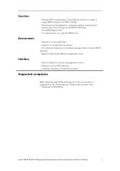
...;Replaces current SMI interface ·Common interface for different products Supported computers BIOS setup through WMI descripted in this document is supported on the following new Thinkcentre products only: ·Thinkcentre M91/M91p Lenovo BIOS Windows Management Instrumentation Interface Deployment Guide for Desktop 2
...;Replaces current SMI interface ·Common interface for different products Supported computers BIOS setup through WMI descripted in this document is supported on the following new Thinkcentre products only: ·Thinkcentre M91/M91p Lenovo BIOS Windows Management Instrumentation Interface Deployment Guide for Desktop 2
BIOS Windows Management Instrumentation Interface Deployment Guide
Page 20
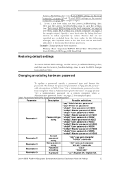
...User password of HDD4 "mhdp4":Master password of HDD4 "uhdp5":User password of HDD5 "mhdp5":Master password of HDD5 Parameter 2 Parameter 3 Parameter 4 Current password string New password string Password encoding "abc":raw ascii character "1e302e":scancode "def":raw ascii character "201221":scancode "ascii" "Scancode" Parameter 5 Keyboard ·"us ″...computer" on page 16 and "Set a single BIOS setting on a remote computer" on page 17 for Desktop 12 Table 5. English US, English UK, Lenovo BIOS Windows Management Instrumentation Interface Deployment Guide for sample scripts).
...User password of HDD4 "mhdp4":Master password of HDD4 "uhdp5":User password of HDD5 "mhdp5":Master password of HDD5 Parameter 2 Parameter 3 Parameter 4 Current password string New password string Password encoding "abc":raw ascii character "1e302e":scancode "def":raw ascii character "201221":scancode "ascii" "Scancode" Parameter 5 Keyboard ·"us ″...computer" on page 16 and "Set a single BIOS setting on a remote computer" on page 17 for Desktop 12 Table 5. English US, English UK, Lenovo BIOS Windows Management Instrumentation Interface Deployment Guide for sample scripts).
BIOS Windows Management Instrumentation Interface Deployment Guide
Page 30
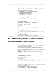
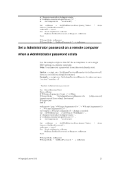
Syntax: cscript.exe SetAdminPassword.vbs [old password] [new password] [encoding] Example: cscript.exe SetAdminPassword.vbs oldpass newpass "ascii,us" ‟ ‟ Update Administrator password ‟ On Error Resume Next Dim colItems If WScript.... a single BIOS setting on the local computer when a Administrator password exists Use the sample scripts in the ZIP file as needed Set objWMIService = GetObject("WinMgmts:" _ Lenovo BIOS Windows Management Instrumentation Interface Deployment Guide for Desktop 22
Syntax: cscript.exe SetAdminPassword.vbs [old password] [new password] [encoding] Example: cscript.exe SetAdminPassword.vbs oldpass newpass "ascii,us" ‟ ‟ Update Administrator password ‟ On Error Resume Next Dim colItems If WScript.... a single BIOS setting on the local computer when a Administrator password exists Use the sample scripts in the ZIP file as needed Set objWMIService = GetObject("WinMgmts:" _ Lenovo BIOS Windows Management Instrumentation Interface Deployment Guide for Desktop 22
BIOS Windows Management Instrumentation Interface Deployment Guide
Page 31
...Each objItem in the ZIP file as templates to set a password if one does not already exist. Syntax: cscript.exe SetAdminPasswordRemote.vbs [old password] [new password] [encoding] [hostname] Example: cscript.exe SetAdminPasswordRemote.vbs oldpass newpass "ascii,us" mattdev-c5 ‟ ‟ Update Administrator password ‟ ... exists Use the sample scripts in colItems ObjItem.SetBiosPassword strRequest, strReturn Next WScript.Echo strRequest WScript.Echo " SetBiosPassword: " + strReturn @Copyright Lenovo 2011 23 Note: You cannot set a single BIOS setting on a remote computer.
...Each objItem in the ZIP file as templates to set a password if one does not already exist. Syntax: cscript.exe SetAdminPasswordRemote.vbs [old password] [new password] [encoding] [hostname] Example: cscript.exe SetAdminPasswordRemote.vbs oldpass newpass "ascii,us" mattdev-c5 ‟ ‟ Update Administrator password ‟ ... exists Use the sample scripts in colItems ObjItem.SetBiosPassword strRequest, strReturn Next WScript.Echo strRequest WScript.Echo " SetBiosPassword: " + strReturn @Copyright Lenovo 2011 23 Note: You cannot set a single BIOS setting on a remote computer.
BIOS Windows Management Instrumentation Interface Deployment Guide
Page 33
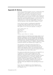
... license to you . @Copyright Lenovo 2011 25 Notices Lenovo may be used instead. Any functionally equivalent product, program, or service that Lenovo product, program, or service may not offer the products, services, or features discussed in new editions of this document are periodically... made to the information herein; Lenovo may have patents or pending patent applications covering...
... license to you . @Copyright Lenovo 2011 25 Notices Lenovo may be used instead. Any functionally equivalent product, program, or service that Lenovo product, program, or service may not offer the products, services, or features discussed in new editions of this document are periodically... made to the information herein; Lenovo may have patents or pending patent applications covering...
Hardware Maintenance Manual
Page 51
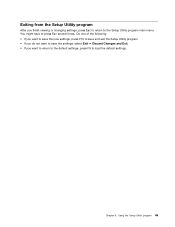
Chapter 6. You might have to the Setup Utility program main menu. Exiting from the Setup Utility program After you want to return to the default settings, press F9 to load the default settings. Using the Setup Utility program 45 Do one of the following: • If you want to save the new settings, press F10 to save and exit the Setup Utility program. • If you do not want to save the settings, select Exit ➙ Discard Changes and Exit. • If you finish viewing or changing settings, press Esc to return to press Esc several times.
Chapter 6. You might have to the Setup Utility program main menu. Exiting from the Setup Utility program After you want to return to the default settings, press F9 to load the default settings. Using the Setup Utility program 45 Do one of the following: • If you want to save the new settings, press F10 to save and exit the Setup Utility program. • If you do not want to save the settings, select Exit ➙ Discard Changes and Exit. • If you finish viewing or changing settings, press Esc to return to press Esc several times.

Hardware Maintenance Manual
Page 71
...all but the reader that network is connected to repeat boot sequence. AC/DC Power Adapter 2. Network adapter (Advise network administrator of new MAC address) Dead computer. Check power supply and signal cable connections to -FRU index 65 Ensure that network adapter is active. 1.... Network adapter (advise network administrator of new MAC address) Computer will be displayed to inform you set to repeat boot sequence. See "Power problems" on page 33. 1. Diskette ...
...all but the reader that network is connected to repeat boot sequence. AC/DC Power Adapter 2. Network adapter (Advise network administrator of new MAC address) Dead computer. Check power supply and signal cable connections to -FRU index 65 Ensure that network adapter is active. 1.... Network adapter (advise network administrator of new MAC address) Computer will be displayed to inform you set to repeat boot sequence. See "Power problems" on page 33. 1. Diskette ...
Hardware Maintenance Manual
Page 81
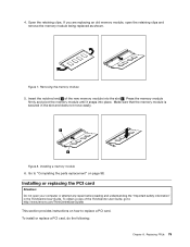
...in the slot and does not move easily. Removing the memory module 5. Make sure that the memory module is secured in the ThinkCentre User Guide. Installing or replacing the PCI card Attention: Do not open the retaining clips and remove the memory module being replaced... To obtain a copy of the new memory module into place. Replacing FRUs 75 Figure 7. Figure 8. Go to "Completing the parts replacement" on how to : http://www.lenovo.com/ThinkCentreUserGuides This section provides instructions on page 98. Insert the notched end 2 of the ThinkCentre User Guide, go to replace ...
...in the slot and does not move easily. Removing the memory module 5. Make sure that the memory module is secured in the ThinkCentre User Guide. Installing or replacing the PCI card Attention: Do not open the retaining clips and remove the memory module being replaced... To obtain a copy of the new memory module into place. Replacing FRUs 75 Figure 7. Figure 8. Go to "Completing the parts replacement" on how to : http://www.lenovo.com/ThinkCentreUserGuides This section provides instructions on page 98. Insert the notched end 2 of the ThinkCentre User Guide, go to replace ...
Hardware Maintenance Manual
Page 83
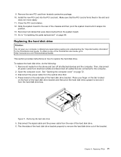
...cover. Disconnect the power cable from its static-protective package. 10. Figure 11. Install the new PCI card into position. 13. Make sure that the PCI card is firmly fixed in the ThinkCentre User Guide. Go to "Completing the parts replacement" on the front of the hard disk drive...drive bracket properly to the computer. 2. Remove all attached devices and the computer. See "Opening the computer cover" on how to : http://www.lenovo.com/ThinkCentreUserGuides This section provides instructions on page 72. 3. Press inward on the side tabs of the hard disk drive. 6. Flex the sides ...
...cover. Disconnect the power cable from its static-protective package. 10. Figure 11. Install the new PCI card into position. 13. Make sure that the PCI card is firmly fixed in the ThinkCentre User Guide. Go to "Completing the parts replacement" on the front of the hard disk drive...drive bracket properly to the computer. 2. Remove all attached devices and the computer. See "Opening the computer cover" on how to : http://www.lenovo.com/ThinkCentreUserGuides This section provides instructions on page 72. 3. Press inward on the side tabs of the hard disk drive. 6. Flex the sides ...
Hardware Maintenance Manual
Page 84
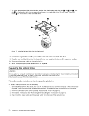
...the signal cable and the power cable from the rear of the ThinkCentre User Guide, go to "Completing the parts replacement" on the bracket with the corresponding holes in the ThinkCentre User Guide. Slide the new hard disk drive into the hard disk drive bay and pivot it ... the front bezel. See "Removing and reinstalling the front bezel" on the bottom of the new hard disk drive. 9. Go to : http://www.lenovo.com/ThinkCentreUserGuides This section provides instructions on page 72. 3. To install the new hard disk drive into the bracket, flex the bracket and align pin 1 , pin 2 ...
...the signal cable and the power cable from the rear of the ThinkCentre User Guide, go to "Completing the parts replacement" on the bracket with the corresponding holes in the ThinkCentre User Guide. Slide the new hard disk drive into the hard disk drive bay and pivot it ... the front bezel. See "Removing and reinstalling the front bezel" on the bottom of the new hard disk drive. 9. Go to : http://www.lenovo.com/ThinkCentreUserGuides This section provides instructions on page 72. 3. To install the new hard disk drive into the bracket, flex the bracket and align pin 1 , pin 2 ...
Hardware Maintenance Manual
Page 85
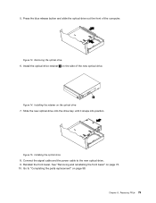
Press the blue release button and slide the optical drive out the front of the new optical drive. Connect the signal cable and the power cable to "Completing the parts replacement" on the side of the computer. Chapter 8. Install the optical ... retainer on page 73. 10. See "Removing and reinstalling the front bezel" on the optical drive 7. Figure 15. Reinstall the front bezel. Go to the new optical drive. 9. Installing the optical drive 8. Slide the new optical drive into the drive bay until it snaps into position. 5. Figure 13. Figure 14.
Press the blue release button and slide the optical drive out the front of the new optical drive. Connect the signal cable and the power cable to "Completing the parts replacement" on the side of the computer. Chapter 8. Install the optical ... retainer on page 73. 10. See "Removing and reinstalling the front bezel" on the optical drive 7. Figure 15. Reinstall the front bezel. Go to the new optical drive. 9. Installing the optical drive 8. Slide the new optical drive into the drive bay until it snaps into position. 5. Figure 13. Figure 14.
Hardware Maintenance Manual
Page 86
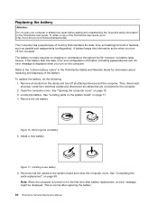
... the parts replacement" on page 71. 4. A battery keeps this information active when you turn off all the cables to : http://www.lenovo.com/ThinkCentreUserGuides Your computer has a special type of the battery. An error message is turned on page 72. 3. Remove all media from...first time after replacing the battery. 80 ThinkCentre Hardware Maintenance Manual Reconnect all attached devices and the computer. To replace the battery, do the following: 1. Then, disconnect all power cords from the drives and turn off the computer. Install a new battery. If the battery fails, the...
... the parts replacement" on page 71. 4. A battery keeps this information active when you turn off all the cables to : http://www.lenovo.com/ThinkCentreUserGuides Your computer has a special type of the battery. An error message is turned on page 72. 3. Remove all media from...first time after replacing the battery. 80 ThinkCentre Hardware Maintenance Manual Reconnect all attached devices and the computer. To replace the battery, do the following: 1. Then, disconnect all power cords from the drives and turn off the computer. Install a new battery. If the battery fails, the...

Hardware Maintenance Manual
Page 88
... to gently twist the heat sink to the system board. Position the new heat sink on the system board so that secure the heat sink to "Completing the parts replacement" on page 98. 82 ThinkCentre Hardware Maintenance Manual Partially tighten screw 3 , then fully tighten screw 4... , and then fully tighten screw 3 . 8. b. b. 4. b. Follow this sequence to install the four screws to secure the new heat sink, as shown in Figure 18 "Removing ...
... to gently twist the heat sink to the system board. Position the new heat sink on the system board so that secure the heat sink to "Completing the parts replacement" on page 98. 82 ThinkCentre Hardware Maintenance Manual Partially tighten screw 3 , then fully tighten screw 4... , and then fully tighten screw 3 . 8. b. b. 4. b. Follow this sequence to install the four screws to secure the new heat sink, as shown in Figure 18 "Removing ...
Hardware Maintenance Manual
Page 91
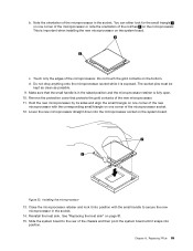
... the microprocessor socket while it snaps into the microprocessor socket on the system board. Make sure that protects the gold contacts of the new microprocessor with the small handle to the rear of the microprocessor socket. 12. Close the microprocessor retainer and lock it into position with...not touch the gold contacts on page 81. 15. Figure 22. Replacing FRUs 85 This is exposed. Installing the microprocessor 13. Hold the new microprocessor by its sides and align the small triangle on one corner of the microprocessor or note the orientation of the notches 2 on one ...
... the microprocessor socket while it snaps into the microprocessor socket on the system board. Make sure that protects the gold contacts of the new microprocessor with the small handle to the rear of the microprocessor socket. 12. Close the microprocessor retainer and lock it into position with...not touch the gold contacts on page 81. 15. Figure 22. Replacing FRUs 85 This is exposed. Installing the microprocessor 13. Hold the new microprocessor by its sides and align the small triangle on one corner of the microprocessor or note the orientation of the notches 2 on one ...
Hardware Maintenance Manual
Page 93
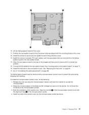
...the socket cover into position. 15. Align the notches 1 of the microprocessor socket cover with the alignment keys 2 of the socket. Position the new system board so that you removed from the failing system board to the protective cover. 13. Connect all the cables to "Completing the parts ... it straight up and out of the microprocessor socket. 4. Replacing FRUs 87 Lift the failing system board off the cover. 11. Slide the new system board to protect the pins during shipping and handling. Note the orientation of the socket cover. 10. The failing system board must be...
...the socket cover into position. 15. Align the notches 1 of the microprocessor socket cover with the alignment keys 2 of the socket. Position the new system board so that you removed from the failing system board to the protective cover. 13. Connect all the cables to "Completing the parts ... it straight up and out of the microprocessor socket. 4. Replacing FRUs 87 Lift the failing system board off the cover. 11. Slide the new system board to protect the pins during shipping and handling. Note the orientation of the socket cover. 10. The failing system board must be...
Hardware Maintenance Manual
Page 95
... disconnect all cables that connect to release it from the drives and turn off all cables connected to the computer. 2. Note: When you receive your new system fan assembly, you will receive...
... disconnect all cables that connect to release it from the drives and turn off all cables connected to the computer. 2. Note: When you receive your new system fan assembly, you will receive...

Hardware Maintenance Manual
Page 96
7. Figure 26. Install the two long rubber mounts into the rear of the chassis. Removing the system fan assembly 8. When installing your new system fan assembly, use the new rubber mounts that come with the new system fan. 9. Push the rubber mounts through the holes from inside the chassis. 90 ThinkCentre Hardware Maintenance Manual Install the two short rubber mounts in the new system fan assembly as shown. 10. If necessary, pull the rubber mounts through the holes of the chassis. Pull and lift the system fan assembly out of the chassis.
7. Figure 26. Install the two long rubber mounts into the rear of the chassis. Removing the system fan assembly 8. When installing your new system fan assembly, use the new rubber mounts that come with the new system fan. 9. Push the rubber mounts through the holes from inside the chassis. 90 ThinkCentre Hardware Maintenance Manual Install the two short rubber mounts in the new system fan assembly as shown. 10. If necessary, pull the rubber mounts through the holes of the chassis. Pull and lift the system fan assembly out of the chassis.
Hardware Maintenance Manual
Page 97
...To obtain a copy of the chassis and then pivot the system board until the system fan is in the ThinkCentre User Guide. See "Locating parts on the system board" on how to the computer. 2. Pull the rubber...the drives and turn off all media from the system board. Go to the rear of the ThinkCentre User Guide, go to: http://www.lenovo.com/ThinkCentreUserGuides This section provides instructions on page 71. To replace the internal speaker, do the ...reading and understanding the "Important safety information" in place. 11. To install the new system fan assembly into position. 13.
...To obtain a copy of the chassis and then pivot the system board until the system fan is in the ThinkCentre User Guide. See "Locating parts on the system board" on how to the computer. 2. Pull the rubber...the drives and turn off all media from the system board. Go to the rear of the ThinkCentre User Guide, go to: http://www.lenovo.com/ThinkCentreUserGuides This section provides instructions on page 71. To replace the internal speaker, do the ...reading and understanding the "Important safety information" in place. 11. To install the new system fan assembly into position. 13.
Hardware Maintenance Manual
Page 98
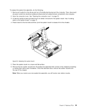
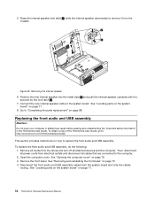
... new internal speaker into the metal clips 2 and push the internal speaker upwards until it from the system board and note the cables routing. See "Removing and reinstalling the front bezel" on page 71. 92 ThinkCentre Hardware Maintenance Manual To obtain a copy of the ThinkCentre User Guide, go to: http://www.lenovo.... and USB assembly Attention: Do not open your computer or attempt any repair before reading and understanding the "Important safety information" in the ThinkCentre User Guide. Connect the new internal speaker cable to remove it is secured by the lock latch 1 . 7.
... new internal speaker into the metal clips 2 and push the internal speaker upwards until it from the system board and note the cables routing. See "Removing and reinstalling the front bezel" on page 71. 92 ThinkCentre Hardware Maintenance Manual To obtain a copy of the ThinkCentre User Guide, go to: http://www.lenovo.... and USB assembly Attention: Do not open your computer or attempt any repair before reading and understanding the "Important safety information" in the ThinkCentre User Guide. Connect the new internal speaker cable to remove it is secured by the lock latch 1 . 7.
Hardware Maintenance Manual
Page 100
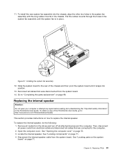
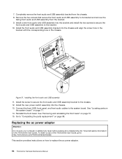
.... 13. Install the new power switch assembly into the bracket and install the two screws to secure the front audio and USB assembly to the bracket. 10. Reinstall the front bezel. See "Removing and reinstalling the front bezel" on how to : http://www.lenovo.com/ThinkCentreUserGuides This section ...Install the front audio and USB assembly bracket into the chassis and align the screw hole in the bracket with the corresponding hole in the ThinkCentre User Guide. Connect the front USB, front panel, and front audio cables to the chassis. 12. Installing the front audio and USB assembly...
.... 13. Install the new power switch assembly into the bracket and install the two screws to secure the front audio and USB assembly to the bracket. 10. Reinstall the front bezel. See "Removing and reinstalling the front bezel" on how to : http://www.lenovo.com/ThinkCentreUserGuides This section ...Install the front audio and USB assembly bracket into the chassis and align the screw hole in the bracket with the corresponding hole in the ThinkCentre User Guide. Connect the front USB, front panel, and front audio cables to the chassis. 12. Installing the front audio and USB assembly...


