(English) Rescue and Recovery 4.3 Deployment Guide
Page 14
...the Rescue and Recovery program, see the Lenovo Web site: http://www.lenovo.com/thinkvantage Requirements for non-Lenovo computers Installation on Think branded systems. For best results, make sure that you have the latest version of non-shared memory, the Rescue and Recovery program will be... a resolution of 800 x 600 and 24-bit color. Requirements for Lenovo computers Lenovo-branded computers must have the following requirements to customize installations, such as a Basic MSI project. In non-shared memory configurations, 120 MB of free hard disk space. Note: When installing ...
...the Rescue and Recovery program, see the Lenovo Web site: http://www.lenovo.com/thinkvantage Requirements for non-Lenovo computers Installation on Think branded systems. For best results, make sure that you have the latest version of non-shared memory, the Rescue and Recovery program will be... a resolution of 800 x 600 and 24-bit color. Requirements for Lenovo computers Lenovo-branded computers must have the following requirements to customize installations, such as a Basic MSI project. In non-shared memory configurations, 120 MB of free hard disk space. Note: When installing ...
(English) Rescue and Recovery 4.3 Deployment Guide
Page 15
On shared video memory systems: a minimum of 4MB and maximum of 8 MB can be compatible with the Rescue and Recovery software. For additional information see the Lenovo Web site at: http://www.lenovo.com/thinkvantage Network adapters for the Rescue and Recovery program: The Rescue and Recovery environment supports only ...Storage specification for boot-ability Video requirements: v Video compatibility: VGA-compatible video that supports a resolution of 800 x 600 and 24-bit color v Video memory: - For supported Lenovo computers, required drivers are independent of the Windows operating system.
On shared video memory systems: a minimum of 4MB and maximum of 8 MB can be compatible with the Rescue and Recovery software. For additional information see the Lenovo Web site at: http://www.lenovo.com/thinkvantage Network adapters for the Rescue and Recovery program: The Rescue and Recovery environment supports only ...Storage specification for boot-ability Video requirements: v Video compatibility: VGA-compatible video that supports a resolution of 800 x 600 and 24-bit color v Video memory: - For supported Lenovo computers, required drivers are independent of the Windows operating system.
(English) Rescue and Recovery 4.3 Deployment Guide
Page 59
New rollouts" v "Scenario 2 - Standalone install for CD or script files" on Lenovo-branded computers. New rollouts This section describes installing the Rescue and Recovery program in a new rollout on page 57...process is the extraction of your donor system as second hard disk drives, USB hard disk drives, USB memory keys and PC Card Memory from the donor system, except the primary hard disk that the installation file is located in the installation ...to install and configure the Rescue and Recovery program for an :: administrative installation. © Copyright Lenovo 2008, 2009 51
New rollouts" v "Scenario 2 - Standalone install for CD or script files" on Lenovo-branded computers. New rollouts This section describes installing the Rescue and Recovery program in a new rollout on page 57...process is the extraction of your donor system as second hard disk drives, USB hard disk drives, USB memory keys and PC Card Memory from the donor system, except the primary hard disk that the installation file is located in the installation ...to install and configure the Rescue and Recovery program for an :: administrative installation. © Copyright Lenovo 2008, 2009 51
(English) Rescue and Recovery 4.5 Deployment Guide
Page 10
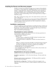
... Recovery installation package, an administrative installation unpacks the installation source files to the Lenovo Web site at http://support.lenovo.com. To obtain the latest version of non-shared memory, the Rescue and Recovery program will be unable to specify the extract location...system: Windows 7 • Microprocessor: supports the 64-bit architecture • Memory: 1 GB - In shared memory configurations, the BIOS setting for Lenovo computers To install the Rescue and Recovery program, Lenovo-branded computers must have the latest version of the Rescue and Recovery program. ...
... Recovery installation package, an administrative installation unpacks the installation source files to the Lenovo Web site at http://support.lenovo.com. To obtain the latest version of non-shared memory, the Rescue and Recovery program will be unable to specify the extract location...system: Windows 7 • Microprocessor: supports the 64-bit architecture • Memory: 1 GB - In shared memory configurations, the BIOS setting for Lenovo computers To install the Rescue and Recovery program, Lenovo-branded computers must have the latest version of the Rescue and Recovery program. ...
(English) Rescue and Recovery 4.5 Deployment Guide
Page 51
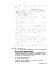
... Windows on the primary hard disk drive. 1. Installing with a clean hard disk drive, you will reduce the installation time on Lenovo-branded computers. Attention: Running this command will extract the WWW EXE to install and configure the Rescue and Recovery program for the z936zisXXXXus00...on page 49 • "Scenario 5 - Build your donor system as second hard disk drives, USB hard disk drives, USB memory keys and PC Card Memory from the target hard disk drive. 2. Within this process one storage device attached). Manually creating the Service Partition of S drive...
... Windows on the primary hard disk drive. 1. Installing with a clean hard disk drive, you will reduce the installation time on Lenovo-branded computers. Attention: Running this command will extract the WWW EXE to install and configure the Rescue and Recovery program for the z936zisXXXXus00...on page 49 • "Scenario 5 - Build your donor system as second hard disk drives, USB hard disk drives, USB memory keys and PC Card Memory from the target hard disk drive. 2. Within this process one storage device attached). Manually creating the Service Partition of S drive...
Hardware Maintenance Manual for ThinkCentre M90z
Page 5
... electrostatic discharge-sensitive devices 5 Grounding requirements 6 Safety notices (multi-lingual translations) . . . . . 6 Chapter 3. Diagnostics 35 Lenovo ThinkVantage Toolbox 35 Lenovo Solution Center 35 PC-Doctor for Rescue and Recovery 36 PC-Doctor for DOS 36 Creating a diagnostic disc 36 Running the diagnostic program ...or reinstalling the wall mount cover . . 75 Removing or reinstalling the wall mount . . . . . 76 Installing or replacing a memory module . . . . 77 Replacing the battery 78 Replacing the hard disk drive 80 Replacing the optical drive 81 Replacing the heat sink...
... electrostatic discharge-sensitive devices 5 Grounding requirements 6 Safety notices (multi-lingual translations) . . . . . 6 Chapter 3. Diagnostics 35 Lenovo ThinkVantage Toolbox 35 Lenovo Solution Center 35 PC-Doctor for Rescue and Recovery 36 PC-Doctor for DOS 36 Creating a diagnostic disc 36 Running the diagnostic program ...or reinstalling the wall mount cover . . 75 Removing or reinstalling the wall mount . . . . . 76 Installing or replacing a memory module . . . . 77 Replacing the battery 78 Replacing the hard disk drive 80 Replacing the optical drive 81 Replacing the heat sink...

Hardware Maintenance Manual for ThinkCentre M90z
Page 50
... Flash the system. System board 1. System board Information only Restart the test, if necessary 1. Press F3 to reset the log file. 44 ThinkCentre Hardware Maintenance Manual See "Flash update procedures" on page 273. 3. Flash the system. See "Flash update procedures" on page 273. 2. ..."Flash update procedures" on page 273. 2. Diagnostic error codes Refer to the following index, X can represent any number. Flash the system. Run memory test 4. See "Flash update procedures" on page 273. 2. See "Flash update procedures" on page 273. 2. See "Flash update procedures" on ...
... Flash the system. System board 1. System board Information only Restart the test, if necessary 1. Press F3 to reset the log file. 44 ThinkCentre Hardware Maintenance Manual See "Flash update procedures" on page 273. 3. Flash the system. See "Flash update procedures" on page 273. 2. ..."Flash update procedures" on page 273. 2. Diagnostic error codes Refer to the following index, X can represent any number. Flash the system. Run memory test 4. See "Flash update procedures" on page 273. 2. See "Flash update procedures" on page 273. 2. See "Flash update procedures" on ...

Hardware Maintenance Manual for ThinkCentre M90z
Page 51
... to -FRU Index 45 Flash the system. Symptom-to "Undetermined problems" on page 64. 2. See "Flash update procedures" on page 39. 2. Reboot the system. 2. Run memory test. 4. System board System board System board Chapter 7. Replace the component that is called out is called out in warning statement 4. System board No action...
... to -FRU Index 45 Flash the system. Symptom-to "Undetermined problems" on page 64. 2. See "Flash update procedures" on page 39. 2. Reboot the system. 2. Run memory test. 4. System board System board System board Chapter 7. Replace the component that is called out is called out in warning statement 4. System board No action...

Hardware Maintenance Manual for ThinkCentre M90z
Page 57
... connected and/or enabled. 2. Replace the component under function test. 1. Remove USB device(s) and re-test. 2. Remove USB device(s) and re-test. 2. System board 1. Run memory test. 4. Symptom-to "Undetermined problems" on page 64. 2. System board System board 1. See "Flash update procedures" on page 39. 2. Chapter 7. See Chapter 6 "Using the Setup...
... connected and/or enabled. 2. Replace the component under function test. 1. Remove USB device(s) and re-test. 2. Remove USB device(s) and re-test. 2. System board 1. Run memory test. 4. Symptom-to "Undetermined problems" on page 64. 2. System board System board 1. See "Flash update procedures" on page 39. 2. Chapter 7. See Chapter 6 "Using the Setup...

Hardware Maintenance Manual for ThinkCentre M90z
Page 65
... enabled. Go to -FRU Index 59 Check power supply voltages. 3. System board 185-278-XXX Asset Security Chassis Intrusion 1. System board 201-000-XXX System Memory Test Passed No action Chapter 7. Microprocessor 3. If a component is connected and/or enabled . 2. Flash the system and re-test. See "Flash update procedures" on page...
... enabled. Go to -FRU Index 59 Check power supply voltages. 3. System board 185-278-XXX Asset Security Chassis Intrusion 1. System board 201-000-XXX System Memory Test Passed No action Chapter 7. Microprocessor 3. If a component is connected and/or enabled . 2. Flash the system and re-test. See "Flash update procedures" on page...

Hardware Maintenance Manual for ThinkCentre M90z
Page 66
... power supply voltages 3. System board No action Remove the Joystick and re-test the system. 60 ThinkCentre Hardware Maintenance Manual Diagnostic Error Code 201-XXX-XXX System Memory error 202-000-XXX System Cache Test Passed 202-XXX-XXX System Cache error 206-000-XXX Diskette...-ROM drive 4. System board 3. System board No action 1. Hard Disk Drive Cable 2. Hard Disk drive (SCSI) 5. System board No action 1. Replace the memory module called out by the test. 2. Mouse 2. Hard Disk drive (IDE) 5. Remove the Hi-Capacity Cartridge Drive and re-test the system. 1. Check ...
... power supply voltages 3. System board No action Remove the Joystick and re-test the system. 60 ThinkCentre Hardware Maintenance Manual Diagnostic Error Code 201-XXX-XXX System Memory error 202-000-XXX System Cache Test Passed 202-XXX-XXX System Cache error 206-000-XXX Diskette...-ROM drive 4. System board 3. System board No action 1. Hard Disk Drive Cable 2. Hard Disk drive (SCSI) 5. System board No action 1. Replace the memory module called out by the test. 2. Mouse 2. Hard Disk drive (IDE) 5. Remove the Hi-Capacity Cartridge Drive and re-test the system. 1. Check ...

Hardware Maintenance Manual for ThinkCentre M90z
Page 67
...in order. 1. Perform the following actions in order. 1. See Chapter 6 "Using the Setup Utility program" on page 39. 2. Make sure the memory module(s) are tones or a series of tones separated by pauses (intervals without sound) during POST. System board No action Remove the Modem and re... a POST/BIOS update failure" on page 274. 3. Video card 5. See Chapter 6 "Using the Setup Utility program" on page 39. 2. Replace the memory module(s). 3. Replace the system board. Diagnostic Error Code 305-000-XXX Monitor DDC Test Passed 305-250-XXX Monitor DDC self test failure 415-000...
...in order. 1. Perform the following actions in order. 1. See Chapter 6 "Using the Setup Utility program" on page 39. 2. Make sure the memory module(s) are tones or a series of tones separated by pauses (intervals without sound) during POST. System board No action Remove the Modem and re... a POST/BIOS update failure" on page 274. 3. Video card 5. See Chapter 6 "Using the Setup Utility program" on page 39. 2. Replace the memory module(s). 3. Replace the system board. Diagnostic Error Code 305-000-XXX Monitor DDC Test Passed 305-250-XXX Monitor DDC self test failure 415-000...
Hardware Maintenance Manual for ThinkCentre M90z
Page 68
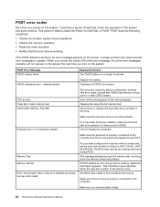
...error halt condition in Setup to find or initialize the hard disk drive controller or the drive. Make sure you have bootable media. 62 ThinkCentre Hardware Maintenance Manual If no longer functional. If POST detects an error during POST. POST does the following operations. • Checks some... the system, it performs a series of tests that check the operation of the system and some basic system-board operations • Checks the memory operation • Starts the video operation • Verifies that the boot drive is working If the POST detects a problem, an error message...
...error halt condition in Setup to find or initialize the hard disk drive controller or the drive. Make sure you have bootable media. 62 ThinkCentre Hardware Maintenance Manual If no longer functional. If POST detects an error during POST. POST does the following operations. • Checks some... the system, it performs a series of tests that check the operation of the system and some basic system-board operations • Checks the memory operation • Starts the video operation • Verifies that the boot drive is working If the POST detects a problem, an error message...

Hardware Maintenance Manual for ThinkCentre M90z
Page 69
...set to right of characters and color bars 1. Ensure that network adapter is active. 1. Run the Memory tests. 2. Riser card, if installed. System Board 2. Memory Module 3. System Board "Insert a Diskette" icon appears with a known-good diagnostics diskette in Setup/... Diskette drive in startup sequence as first device or first device after diskette. 2. Diskette Drive 2. Hard Disk Drive Cable Incorrect memory size during POST 1. Symptom-to network adapter. 2. Network adapter (Advise network administrator of new MAC address) Dead computer. System...
...set to right of characters and color bars 1. Ensure that network adapter is active. 1. Run the Memory tests. 2. Riser card, if installed. System Board 2. Memory Module 3. System Board "Insert a Diskette" icon appears with a known-good diagnostics diskette in Setup/... Diskette drive in startup sequence as first device or first device after diskette. 2. Diskette Drive 2. Hard Disk Drive Cable Incorrect memory size during POST 1. Symptom-to network adapter. 2. Network adapter (Advise network administrator of new MAC address) Dead computer. System...
Hardware Maintenance Manual for ThinkCentre M90z
Page 70
... light not on how to find out the failing devices or adapters. 1. System Board Serial or parallel port device failure (adapter port) 1. Alternate Adapter 5. Memory modules 64 ThinkCentre Hardware Maintenance Manual System Board Printer problems 1. Hard disk drive RPL computer does not RPL from its own hard 1. Serial or parallel port device...
... light not on how to find out the failing devices or adapters. 1. System Board Serial or parallel port device failure (adapter port) 1. Alternate Adapter 5. Memory modules 64 ThinkCentre Hardware Maintenance Manual System Board Printer problems 1. Hard disk drive RPL computer does not RPL from its own hard 1. Serial or parallel port device...
Hardware Maintenance Manual for ThinkCentre M90z
Page 71
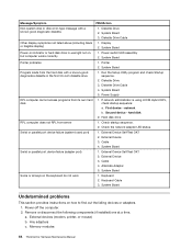
Diskette drive 3. Repeat steps 1 through 3 until you find the failing device or adapter. Hard disk drive h. External Cache RAM g. If all devices and adapters have been removed, and the problem continues, replace the system board. Symptom-to re-test the system. 4. Power-on the computer to -FRU Index 65 d. External Cache f. Chapter 7. Extended video memory e.
Diskette drive 3. Repeat steps 1 through 3 until you find the failing device or adapter. Hard disk drive h. External Cache RAM g. If all devices and adapters have been removed, and the problem continues, replace the system board. Symptom-to re-test the system. 4. Power-on the computer to -FRU Index 65 d. External Cache f. Chapter 7. Extended video memory e.

Hardware Maintenance Manual for ThinkCentre M90z
Page 75
Figure 3. Component locations 1 Frame stand 2 Wall mount cover 3 Fan duct 4 Heat sink 5 Memory modules (2) 6 WI-FI card* 7 Microprocessor fan 8 Battery 9 ExpressCard* 10 Rear I/O assembly 11 Internal speaker 12 Bluetooth module* 17 Touch panel control board 18 Power switch module 19 Hard disk drive 20 Right I/O assembly 21 Card reader* 22 Optical drive bay 23 Inverter 24 Computer main bracket 25 LCD panel 26 Optical drive* 27 Power supply 28 Integrated camera with microphone* Chapter 8. Replacing FRUs 69 FRU locations The following illustration shows the locations of the FRUs.
Figure 3. Component locations 1 Frame stand 2 Wall mount cover 3 Fan duct 4 Heat sink 5 Memory modules (2) 6 WI-FI card* 7 Microprocessor fan 8 Battery 9 ExpressCard* 10 Rear I/O assembly 11 Internal speaker 12 Bluetooth module* 17 Touch panel control board 18 Power switch module 19 Hard disk drive 20 Right I/O assembly 21 Card reader* 22 Optical drive bay 23 Inverter 24 Computer main bracket 25 LCD panel 26 Optical drive* 27 Power supply 28 Integrated camera with microphone* Chapter 8. Replacing FRUs 69 FRU locations The following illustration shows the locations of the FRUs.
Hardware Maintenance Manual for ThinkCentre M90z
Page 76
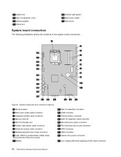
... SATA connector 23 Optical drive power connector 24 Low-voltage differential signaling (LVDS) cable connector 70 ThinkCentre Hardware Maintenance Manual System board part and connector locations 1 Microprocessor 2 Multi-touch board cable connector 3 Integrated camera cable connector 4 Memory slots (2) 5 Mini PCI Express slot 6 Ambient light sensor cable connector 7 Bluetooth module cable connector 8 Wireless...
... SATA connector 23 Optical drive power connector 24 Low-voltage differential signaling (LVDS) cable connector 70 ThinkCentre Hardware Maintenance Manual System board part and connector locations 1 Microprocessor 2 Multi-touch board cable connector 3 Integrated camera cable connector 4 Memory slots (2) 5 Mini PCI Express slot 6 Ambient light sensor cable connector 7 Bluetooth module cable connector 8 Wireless...

Hardware Maintenance Manual for ThinkCentre M90z
Page 83
... Go to a maximum of 4 GB of system memory. Remove all media from electrical outlets and disconnect all attached devices and the computer. Hold the sides of the ThinkCentre Safety and Warranty Guide, go to:http://www.lenovo.com/support This section provides instructions on page 110.... and understanding the "Important safety information" in any combination up . 3. When installing or replacing a memory module, use 1 gigabytes (GB) or 2 GB DDR3 SODIMMs in the ThinkCentre Safety and Warranty Guide that are connected to the system board. Remove the computer cover. Chapter 8. See...
... Go to a maximum of 4 GB of system memory. Remove all media from electrical outlets and disconnect all attached devices and the computer. Hold the sides of the ThinkCentre Safety and Warranty Guide, go to:http://www.lenovo.com/support This section provides instructions on page 110.... and understanding the "Important safety information" in any combination up . 3. When installing or replacing a memory module, use 1 gigabytes (GB) or 2 GB DDR3 SODIMMs in the ThinkCentre Safety and Warranty Guide that are connected to the system board. Remove the computer cover. Chapter 8. See...
Hardware Maintenance Manual for ThinkCentre M90z
Page 84
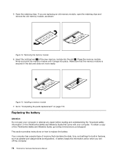
.... Go to replace the battery. To obtain a copy of the ThinkCentre Safety and Warranty Guide, go to:http://www.lenovo.com/support This section provides instructions on how to "Completing the parts replacement" on page 110. Insert the notched end 2 of memory that maintains the date, time, and settings for built-in the...
.... Go to replace the battery. To obtain a copy of the ThinkCentre Safety and Warranty Guide, go to:http://www.lenovo.com/support This section provides instructions on how to "Completing the parts replacement" on page 110. Insert the notched end 2 of memory that maintains the date, time, and settings for built-in the...


