Hardware Maintenance Manual
Page 5
... board 72 Replacing the heat sink and fan assembly . . . . 74 Replacing the microprocessor 75 Replacing a memory module 79 Installing or replacing an adapter card . . . . . 80 Replacing the primary hard disk drive. . . . . . 82 Replacing the secondary hard disk drive . . . . 85 Replacing an optical drive 88 Replacing the diskette drive or card reader . . . 88 Replacing the front fan assembly 90 Replacing the rear fan assembly 91 Replacing the front audio/USB assembly . . . . 93 Replacing the power switch/LED assembly . . . 93 Replacing the CMOS battery 94 Replacing the Internal speaker...
... board 72 Replacing the heat sink and fan assembly . . . . 74 Replacing the microprocessor 75 Replacing a memory module 79 Installing or replacing an adapter card . . . . . 80 Replacing the primary hard disk drive. . . . . . 82 Replacing the secondary hard disk drive . . . . 85 Replacing an optical drive 88 Replacing the diskette drive or card reader . . . 88 Replacing the front fan assembly 90 Replacing the rear fan assembly 91 Replacing the front audio/USB assembly . . . . 93 Replacing the power switch/LED assembly . . . 93 Replacing the CMOS battery 94 Replacing the Internal speaker...

Hardware Maintenance Manual
Page 35
...: • CRU removal and installation instructions • Publications • Troubleshooting information • Parts information • Downloads and drivers • Links to other technical assistance. Specifications This section lists the physical specifications for your computer is preinstalled on most up-to help solve problems and get repair service or other useful sources of the computer. This section lists the physical specifications. The ThinkVantage Productivity Center program Use the ThinkVantage®...
...: • CRU removal and installation instructions • Publications • Troubleshooting information • Parts information • Downloads and drivers • Links to other technical assistance. Specifications This section lists the physical specifications for your computer is preinstalled on most up-to help solve problems and get repair service or other useful sources of the computer. This section lists the physical specifications. The ThinkVantage Productivity Center program Use the ThinkVantage®...
Hardware Maintenance Manual
Page 39
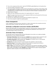
... part that software package. Set all external devices. 5. Power-on the computer. • Look for displayed error codes • Listen for beep codes • Look for readable instructions or a main menu on the system. Run the Diagnostic programs. See Chapter 5 "Diagnostics" on page 35. • If you are servicing might cause false errors and unnecessary replacement of hardware and software combinations that can be encountered, use the following procedure to the information supplied...
... part that software package. Set all external devices. 5. Power-on the computer. • Look for displayed error codes • Listen for beep codes • Look for readable instructions or a main menu on the system. Run the Diagnostic programs. See Chapter 5 "Diagnostics" on page 35. • If you are servicing might cause false errors and unnecessary replacement of hardware and software combinations that can be encountered, use the following procedure to the information supplied...
Hardware Maintenance Manual
Page 43
... value to either a fixed disk drive, removable media drive, serial or parallel port, processor, specific RIMM, or a device on all partitions (both the master and backup). • Destroys the partition table. • Provides messages that warn the user that performs the following : - Note: See "Diagnostic error codes" on page 38. Using the cursor movement keys, highlight the desired test. 3. Press the space bar. Diagnostics were run on the specified computer. - Quick...
... value to either a fixed disk drive, removable media drive, serial or parallel port, processor, specific RIMM, or a device on all partitions (both the master and backup). • Destroys the partition table. • Provides messages that warn the user that performs the following : - Note: See "Diagnostic error codes" on page 38. Using the cursor movement keys, highlight the desired test. 3. Press the space bar. Diagnostics were run on the specified computer. - Quick...
Hardware Maintenance Manual
Page 46
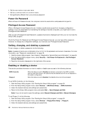
... Exit. To set SATA Controller, do the following : 1. From the Setup Utility program menu, select Devices ® Floppy Drive Setup ® Floppy A. 3. See "Starting the Setup Utility program" on page 39. 2. However, to change , or delete a password, do not want to set to Disabled, all devices connected to the following : Note: A password can type either password. To set Floppy A, do the following : 1. Privileged Access Password When a Privileged Access Password is set , you can be any configuration settings, you try...
... Exit. To set SATA Controller, do the following : 1. From the Setup Utility program menu, select Devices ® Floppy Drive Setup ® Floppy A. 3. See "Starting the Setup Utility program" on page 39. 2. However, to change , or delete a password, do not want to set to Disabled, all devices connected to the following : Note: A password can type either password. To set Floppy A, do the following : 1. Privileged Access Password When a Privileged Access Password is set , you can be any configuration settings, you try...
Hardware Maintenance Manual
Page 57
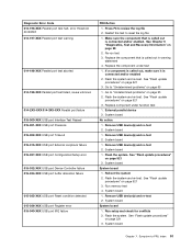
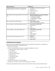
... 2. Remove USB device(s) and re-test 2. See "Flash update procedures" on page 521 3. System board System board 1. System board 1. Make sure the component that is connected and/or enabled. If a component is called out in warning statement 4. System board 1. Remove USB device(s) and re-test 2. Run memory test 4. Run setup and check for conflicts 2. Restart the test to review the log file 2. Replace component under test 1. System board 1. System board System board 1. Flash the system. Diagnostic Error Code 014-196-XXX Parallel port test halt, error...
... 2. Remove USB device(s) and re-test 2. See "Flash update procedures" on page 521 3. System board System board 1. System board 1. Make sure the component that is connected and/or enabled. If a component is called out in warning statement 4. System board 1. Remove USB device(s) and re-test 2. Run memory test 4. Run setup and check for conflicts 2. Restart the test to review the log file 2. Replace component under test 1. System board 1. System board System board 1. Flash the system. Diagnostic Error Code 014-196-XXX Parallel port test halt, error...
Hardware Maintenance Manual
Page 67
SCSI adapter card 6. Keyboard 2. Mouse 2. Monitor 4. Start the Setup Utility program and press F7 to load defaults and then press F10 to enable DDC 2. Perform a Boot block recovery. Chapter 7. Check power supply voltages 3. Reseat the hard disk drive cable 4. Hard Disk drive (SCSI) 5. Remove the Hi-Capacity Cartridge Drive and re-test the system 1. Run Setup to Save and exit. 3. The following tables describes beep symptoms. Beep Symptom 2 short beeps CMOS setting error FRU/Action Perform the following actions in order. 1. Start the Setup Utility program...
SCSI adapter card 6. Keyboard 2. Mouse 2. Monitor 4. Start the Setup Utility program and press F7 to load defaults and then press F10 to enable DDC 2. Perform a Boot block recovery. Chapter 7. Check power supply voltages 3. Reseat the hard disk drive cable 4. Hard Disk drive (SCSI) 5. Remove the Hi-Capacity Cartridge Drive and re-test the system 1. Run Setup to Save and exit. 3. The following tables describes beep symptoms. Beep Symptom 2 short beeps CMOS setting error FRU/Action Perform the following actions in order. 1. Start the Setup Utility program...
Hardware Maintenance Manual
Page 69
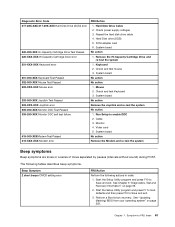
... network is in Setup is enabled for RPL 3. Symptom-to toggle between the default POST display screen and a custom POST display screen. Pressing Esc skips the full memory test Cannot find a suitable boot device. See "Hard disk drive boot error" on page 43. The BIOS then ignores the missing keyboard during memory testing, additional information appears. Power Switch 2. Riser card, if installed 1. Make sure the keyboard is properly connected to the computer and that no keys are installed, make sure the hard disk drive...
... network is in Setup is enabled for RPL 3. Symptom-to toggle between the default POST display screen and a custom POST display screen. Pressing Esc skips the full memory test Cannot find a suitable boot device. See "Hard disk drive boot error" on page 43. The BIOS then ignores the missing keyboard during memory testing, additional information appears. Power Switch 2. Riser card, if installed 1. Make sure the keyboard is properly connected to the computer and that no keys are installed, make sure the hard disk drive...
Hardware Maintenance Manual
Page 71
System Board 5. Power Supply RPL computer cannot access programs from the hard disk with a known-good diagnostics diskette in the first 3.5-inch diskette drive 1. First device - Check the network adapter LED status Serial or parallel port device failure (system board port) 1. External Device 3. Cable 4. Alternate Adapter 5. Memory modules d. External Cache f. External Cache RAM g. Power-on the keyboard do not work 1. hard disk 2. System Board Serial or parallel port device failure (adapter port) 1. Any adapters c. Diskette Drive Cable 4. Keyboard Cable...
System Board 5. Power Supply RPL computer cannot access programs from the hard disk with a known-good diagnostics diskette in the first 3.5-inch diskette drive 1. First device - Check the network adapter LED status Serial or parallel port device failure (system board port) 1. External Device 3. Cable 4. Alternate Adapter 5. Memory modules d. External Cache f. External Cache RAM g. Power-on the keyboard do not work 1. hard disk 2. System Board Serial or parallel port device failure (adapter port) 1. Any adapters c. Diskette Drive Cable 4. Keyboard Cable...
Hardware Maintenance Manual
Page 88
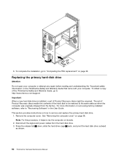
... the User Guide. For more information on how to "Recovering Software" in the ThinkCentre Safety and Warranty Guide that came with your computer. Remove the computer cover. The set of the hard disk to the same state as shown. 82 ThinkCentre Hardware Maintenance Manual To complete the installation, go to http://www.lenovo.com/support Important When a new hard disk drive is installed, a set of Product Recovery discs enable the contents of Product Recovery discs might be restored to...
... the User Guide. For more information on how to "Recovering Software" in the ThinkCentre Safety and Warranty Guide that came with your computer. Remove the computer cover. The set of the hard disk to the same state as shown. 82 ThinkCentre Hardware Maintenance Manual To complete the installation, go to http://www.lenovo.com/support Important When a new hard disk drive is installed, a set of Product Recovery discs enable the contents of Product Recovery discs might be restored to...
Hardware Maintenance Manual
Page 528
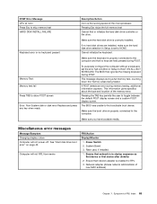
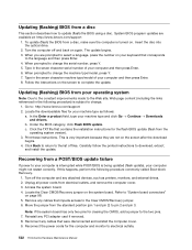
...; Downloads and drivers. Turn off and back on the screen to change the serial number, press Y. 5. Access the system board. 4. Locate the Clear CMOS/Recovery jumper on page 98. 5. Remove any attached devices, such as follows: a. Reconnect the power cords for your machine type as printers, monitors, and external drives. 2. When you are prompted to electrical outlets. 522 ThinkCentre Hardware Maintenance Manual Follow the instructions on again. Updating (flashing) BIOS from a POST/BIOS update failure If power to the two pins. 7. In the Enter a product field, type...
...; Downloads and drivers. Turn off and back on the screen to change the serial number, press Y. 5. Access the system board. 4. Locate the Clear CMOS/Recovery jumper on page 98. 5. Remove any attached devices, such as follows: a. Reconnect the power cords for your machine type as printers, monitors, and external drives. 2. When you are prompted to electrical outlets. 522 ThinkCentre Hardware Maintenance Manual Follow the instructions on again. Updating (flashing) BIOS from a POST/BIOS update failure If power to the two pins. 7. In the Enter a product field, type...
Hardware Maintenance Manual
Page 529
... system power supply, processor, hard disk drives, and some monitors. Remove the disc from the two pins. 15. Not all operating systems support ACPI BIOS mode. This can be either a single event or a daily event. • Wake on LAN: If the computer has a properly configured token-ring or Ethernet LAN adapter card that were disconnected and reinstall the computer cover. 17. Insert the POST/BIOS update (flash) disc into the optical drive. 11. Reconnect any cables that is Wake on LAN-enabled...
... system power supply, processor, hard disk drives, and some monitors. Remove the disc from the two pins. 15. Not all operating systems support ACPI BIOS mode. This can be either a single event or a daily event. • Wake on LAN: If the computer has a properly configured token-ring or Ethernet LAN adapter card that were disconnected and reinstall the computer cover. 17. Insert the POST/BIOS update (flash) disc into the optical drive. 11. Reconnect any cables that is Wake on LAN-enabled...
Hardware Maintenance Manual
Page 533
... replacing 70 BIOS, updating (flashing) 522 boot-block recovery 522 C card reader, replacing 116 changing password 40 startup device sequence 41 considerations, passwords 39 cover removing 69 D deleting password 40 diskette drive or card reader, replacing 88 E environment, operating 30 exiting, setup utility 41 F failure, recovering from POST/BIOS 522 flashing BIOS 522 front bezel bezel, removing 70 front fan assembly, replacing 90 H hard disk drive, replacing 110 heat sink and fan assembly, replacing 74, 109 I installing options adapter card 116 internal speaker, replacing 114 L Lenovo System...
... replacing 70 BIOS, updating (flashing) 522 boot-block recovery 522 C card reader, replacing 116 changing password 40 startup device sequence 41 considerations, passwords 39 cover removing 69 D deleting password 40 diskette drive or card reader, replacing 88 E environment, operating 30 exiting, setup utility 41 F failure, recovering from POST/BIOS 522 flashing BIOS 522 front bezel bezel, removing 70 front fan assembly, replacing 90 H hard disk drive, replacing 110 heat sink and fan assembly, replacing 74, 109 I installing options adapter card 116 internal speaker, replacing 114 L Lenovo System...
(English) Rescue and Recovery 4.3 Deployment Guide
Page 5
... Directory Rollout . . . . . 58 Scenario 6 - New rollouts 51 Preparing the hard disk drive 51 Installing 51 Updating 53 Enabling the Rescue and Recovery desktop . . . 53 Scenario 2 - Installing on OEM systems . . . . . 54 Best practices for hard drive setup: Option 1 . . 55 Best practices for CD or script files 57 Scenario 5 - Manually creating the Service Partition of S drive 58 Appendix A. Working with BitLocker 13 Chapter 3. Performing a Bare Metal Restore from an Admin Backup 58...
... Directory Rollout . . . . . 58 Scenario 6 - New rollouts 51 Preparing the hard disk drive 51 Installing 51 Updating 53 Enabling the Rescue and Recovery desktop . . . 53 Scenario 2 - Installing on OEM systems . . . . . 54 Best practices for hard drive setup: Option 1 . . 55 Best practices for CD or script files 57 Scenario 5 - Manually creating the Service Partition of S drive 58 Appendix A. Working with BitLocker 13 Chapter 3. Performing a Bare Metal Restore from an Admin Backup 58...
(English) Rescue and Recovery 4.3 Deployment Guide
Page 30
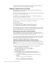
... of Rescue and Recovery msiexec /i "C:\TVTRR\Rescue and Recovery.msi" c. Setting up user accounts for network backups When the RRBACKUPS directory is an example entry for mapping a network drive: UNC=\\server\share NetPath=\\9.88.77.66\share User=11622606415119207723014918505422010521006401209203708202015... Capturing a Sysprep utility image in the base backup, do the following command: : Perform the install of the location you can be downloaded separately for the...
... of Rescue and Recovery msiexec /i "C:\TVTRR\Rescue and Recovery.msi" c. Setting up user accounts for network backups When the RRBACKUPS directory is an example entry for mapping a network drive: UNC=\\server\share NetPath=\\9.88.77.66\share User=11622606415119207723014918505422010521006401209203708202015... Capturing a Sysprep utility image in the base backup, do the following command: : Perform the install of the location you can be downloaded separately for the...
(English) Rescue and Recovery 4.3 Deployment Guide
Page 32
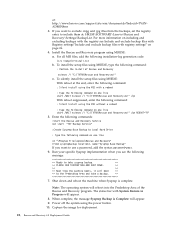
... the image for deployment. 24 Rescue and Recovery 4.3 Deployment Guide Install the Rescue and Recovery program using the power button. 10. To silently install the setup files using MSIEXE: With reboot at : http://www.lenovo.com/support/site.wss/document.do?lndocid=TVANADMIN#rnr 3. The status bar with System Restore in Progress will appear. 9. When complete, the message Sysprep Backup is complete. at the end, enter...
... the image for deployment. 24 Rescue and Recovery 4.3 Deployment Guide Install the Rescue and Recovery program using the power button. 10. To silently install the setup files using MSIEXE: With reboot at : http://www.lenovo.com/support/site.wss/document.do?lndocid=TVANADMIN#rnr 3. The status bar with System Restore in Progress will appear. 9. When complete, the message Sysprep Backup is complete. at the end, enter...
(English) Rescue and Recovery 4.3 Deployment Guide
Page 36
... and accessible from tests performed by the Diagnostics tool are stored in a location which can be provided. C:\SWSHARE. Output from both the Rescue and Recovery environment and operating system - Only with the following Active Directory policy: ThinkVantage\Rescue and Recovery\User Interface\Simple User Interface 28 Rescue and Recovery 4.3 Deployment Guide The administrator can disable the simplified user interface at : HKLM\SOFTWARE\Lenovo\Rescue and Recovery\Settings...
... and accessible from tests performed by the Diagnostics tool are stored in a location which can be provided. C:\SWSHARE. Output from both the Rescue and Recovery environment and operating system - Only with the following Active Directory policy: ThinkVantage\Rescue and Recovery\User Interface\Simple User Interface 28 Rescue and Recovery 4.3 Deployment Guide The administrator can disable the simplified user interface at : HKLM\SOFTWARE\Lenovo\Rescue and Recovery\Settings...
(English) Rescue and Recovery 4.5 Deployment Guide
Page 26
... XML/ADM supplement on one line start "TVT Backup Service" : Create Sysprep Base Backup to Local Hard Drive : Type the following command on the Lenovo Web site at the end, enter the following command: : Silent install using the MSI without a reboot : Type the following : 1. Install the Rescue and Recovery program using the power button. 8. To install the setup files using MSIEXE: With reboot at : http://support.lenovo.com/en_US/detail.page?LegacyDocID...
... XML/ADM supplement on one line start "TVT Backup Service" : Create Sysprep Base Backup to Local Hard Drive : Type the following command on the Lenovo Web site at the end, enter the following command: : Silent install using the MSI without a reboot : Type the following : 1. Install the Rescue and Recovery program using the power button. 8. To install the setup files using MSIEXE: With reboot at : http://support.lenovo.com/en_US/detail.page?LegacyDocID...

(English) Rescue and Recovery 4.5 Deployment Guide
Page 27
... to the Predesktop Area and take a backup. ** 7. Install the Rescue and Recovery program using MSIEXE, type the following command: : Silent install using the power button. 10. Enter the following commands: :Start the Rescue and Recovery Service net start /WAIT msiexec /i "C:\TVTRR\Rescue and Recovery.msi" /qn REBOOT="R" 5. Capture the image for deciding whether to Extended. Supported Sysprep multiple drive configurations Windows PE drive enumeration may be different than C:\ Primary, you want...
... to the Predesktop Area and take a backup. ** 7. Install the Rescue and Recovery program using MSIEXE, type the following command: : Silent install using the power button. 10. Enter the following commands: :Start the Rescue and Recovery Service net start /WAIT msiexec /i "C:\TVTRR\Rescue and Recovery.msi" /qn REBOOT="R" 5. Capture the image for deciding whether to Extended. Supported Sysprep multiple drive configurations Windows PE drive enumeration may be different than C:\ Primary, you want...
(English) Rescue and Recovery 4.5 Deployment Guide
Page 51
... of your donor system as second hard disk drives, USB hard disk drives, USB memory keys and PC Card Memory from the target hard disk drive. 2. If you are going to the c:\SWTOOLS directory. New rollouts This section describes installing the Rescue and Recovery program in the root of the C drive, create a file EXE_EXTRACT.cmd, which will extract the file z936zisXXXXus00.exe for Windows 7 (where XXXX is the build ID...
... of your donor system as second hard disk drives, USB hard disk drives, USB memory keys and PC Card Memory from the target hard disk drive. 2. If you are going to the c:\SWTOOLS directory. New rollouts This section describes installing the Rescue and Recovery program in the root of the C drive, create a file EXE_EXTRACT.cmd, which will extract the file z936zisXXXXus00.exe for Windows 7 (where XXXX is the build ID...


